3. Group resource details
This chapter provides information on group resources that constitute a failover group.
For overview of group resources, see , "Design a system configuration" in the "Installation and Configuration Guide".
This chapter covers:
3.1. Group resources
Currently supported group resources are as follows:
Group resource name |
Abbreviation |
Functional overview |
|---|---|---|
Application resources |
appli |
Refer to "Understanding application resources". |
Floating IP resources |
fip |
Refer to "Understanding floating IP resources". |
Mirror disk resources |
md |
Refer to "Understanding mirror disk resources". |
Registry synchronization resources |
regsync |
Refer to "Understanding registry synchronization resources". |
Script resources |
script |
Refer to "Understanding script resources". |
Disk resources |
sd |
Refer to "Understanding disk resources". |
Service resources |
service |
Refer to "Understanding service resources". |
Print spooler resources |
spool |
Refer to "Understanding print spooler resources". |
Virtual computer name resources |
vcom |
Refer to "Understanding virtual computer name resources". |
Dynamic DNS resources |
ddns |
Refer to "Understanding dynamic DNS resources". |
Virtual IP resources |
vip |
Refer to "Understanding virtual IP resources". |
CIFS resources |
cifs |
Refer to "Understanding CIFS resources ". |
NAS resources |
nas |
Refer to "Understanding NAS resources". |
Hybrid disk resource |
hd |
Refer to "Understanding hybrid disk resources". |
VM resource |
vm |
Refer to "Understanding VM resources". |
AWS elastic ip resource |
awseip |
Refer to "Understanding AWS elastic ip resources". |
AWS virtual ip resource |
awsvip |
Refer to "Understanding AWS virtual ip resources". |
AWS DNS resource |
awsdns |
Refer to "Understanding AWS DNS resources". |
Azure probe port resource |
azurepp |
Refer to "Understanding Azure probe port resources". |
Azure DNS resource |
azuredns |
Refer to "Understanding Azure DNS resources". |
Google Cloud virtual IP resource |
gcvip |
Refer to "Understanding Google Cloud virtual IP resources". |
Google Cloud DNS resource |
gcdns |
Refer to "Understanding Google Cloud DNS resources". |
Oracle Cloud virtual IP resource |
ocvip |
Refer to "Understanding Oracle Cloud virtual IP resources". |
3.2. What is a group?
A group is a unit to perform a failover. Rules regarding to operations at failover (failover policies) can be set per group.
3.2.1. Understanding the group types
Groups fall into two types: virtual machine groups and failover groups.
- Virtual machine groupPerforms failover (migration) for each virtual machine. The following resources can be registered with this group: virtual machine resource, mirror disk resource, disk resource, hybrid disk resource, NAS resource, and script resource.
- Failover groupCollects the resources required for application continuation and performs failover for each application. Up to 256 group resources can be registered with each group. However, no virtual machine resource can be registered.
3.2.2. Understanding the group properties
The properties that can be set on each group are described below:
- Servers that can run the GroupSelect and set the servers that can run the group from the servers that configure a cluster. Specify the order of priority to the servers that can run the group for running the group.
- Startup AttributeSets the startup attribute of a group to the auto startup or manual startup.In the case of the auto startup, when a cluster is started, a group is started up automatically on the server that has the highest priority among the servers that can run the group.In the case of the manual startup, a group is not started even when a server is started up. After starting the server, start up the group manually by using the Cluster WebUI or the clpgrp command. For details on the Cluster WebUI, see online manual. For details on the clpgrp command, see "Operating groups (clpgrp command)" in "EXPRESSCLUSTER command reference" in this guide.
- Failover AttributeSpecify the failover method. The following failover attributes can be specified.Auto FailoverA heartbeat timeout or error detection by a group or monitor resource triggers an automatic failover.For an automatic failover, the following options can be specified.
- Use the startup server settingsWhen failover is executed due to the error detection of the group resource or monitor resource, the failover destination settings of the resource is used (stable server/ the server that has the highest priority). Also, when failing over is executed due to the timeout detection of the heartbeat, the failover destination is determined following the priority of the server set as servers that can run the group.For the operation when a stable server or the server that has the highest priority is used, see "Recovery Operation tab" and "Recovery Action tab".
- Fail over dynamicallyThe failover destination is determined by considering the statuses of each server's monitor resource or failover group, and then a failover is performed.The failover destination is determined in the following way.
Determination factor
Condition
Result
Status of critical monitor resource
Error (all servers)
When there is no failover destination, proceed to forced failover judgment process.
Normal (single server)
A normal server is used as the failover destination.
Normal (multiple servers)
Proceed to the process that compares error levels.
Perform a forced failover
Set
Proceed to the process that ignores the status of the critical monitor resource and which compares error levels for all the activated servers.
Not set
Failover is not performed.
Number of servers that have the lowest error level
1
The server with the lowest error level is used as the failover destination.
Two or more
Proceed to the process that judges whether there is a server that can perform a failover in the server that has the lowest error level and that is in the same server group as the failover source.
Prioritize failover policy in the server group
SetandWithin the same server group as the failover source, there is a server that can perform failover.The server in the same server group is used as the failover destination.
SetandWithin the same server group as the failover source, there is no server that can perform a failover.Proceed to the smart failover judgment process.
Not set
Proceed to the smart failover judgment process.
Perform a smart failover
SetandThe number of servers recommended as the failover destination is 1.The server recommended by the smart failover is used as the failover destination.
SetandThe number of servers recommended as the failover destination is 2 or more.Proceed to the operation level judgment process.
Not set
Proceed to the operation level judgment process.
Number of servers with the lowest operation level
1
The server that has the lowest operation level is used as the failover destination.
Two or more
The running server that has the highest priority is used as the failover destination.
Note
Critical monitor resourceExclude the server which is detecting the error by a monitor resource from the failover destination.The exclusive monitor can be set with the Cluster WebUI.Error levelThis is the number of monitor resources that have detected errors.Smart failoverA function that assigns the server with the smallest load as the failover destination, based on the system resource information collected by the System Resource Agent. To enable this function, a System Resource Agent license must be registered on all the servers set as the failover destination and the system monitor resource must be set as the monitor resource. For details on the system resource monitor, see "Understanding system monitor resources" in "Monitor resource details" in this guide.Operation levelThis is the number of failover groups that have been started or are being started, excluding management group.- Prioritize failover policy in the server groupIf a server in the same server group can be used as the failover destination, this server is preferably used. If no server in the same server group can be used as the failover destination, a server in another server group is used as the failover destination.When failover is executed due to the error detection of the group resource or monitor resource, the failover destination settings of the resource is used (stable server/ the server that has the highest priority). Also, when failing over is executed due to the timeout detection of the heartbeat, the failover destination is determined following the priority of the server set as servers that can run the group.
- Allow only a manual failover between server groupsThis can be selected only when the above Prioritize failover policy in the server group is set.An automatic failover is performed only if a server within the same server group is the destination.If no servers in the same server group can be used as the failover destination, failing over to a server in another server group is not automatically performed.To move the group to a server in another server group, use the Cluster WebUI or clpgrp command.
Manual FailoverFailover is not automatically performed when a heartbeat is timed out. In that case, perform failover manually by using the Cluster WebUI or the clpgrp command. However, even if manual failover is specified, a failover is performed automatically when an error is detected by a group or monitor resource.Note
If Execute Failover to outside the Server Group is set in message receive monitor resource setting, dynamic failover setting and failover setting between server groups will be invalid. A failover is applied to the server that is in a server group other than the server group to which the failover source server belongs and which has the highest priority.
- Failback AttributeSet either auto failback or manual failback. However, this cannot be specified when the following conditions match.
Mirror disk resource or hybrid disk resource is set to fail over group.
Failover attribute is Fail over dynamically.
In the case of the auto failback, failback will be automatically performed when the server that is given the highest priority is started after a failover.In the case of the manual failback, a failback is not performed even if a server is started. - Logical ServiceSet the logical service name.The logical service is the character string that is used as an identifier when using an application which identifies a group by using the compatible API of EXPRESSCLUSTER Ver8.0 or earlier.
3.2.3. Understanding failover policy
A failover policy is a rule that determines a server to be the failover destination from multiple servers, and it is defined by the properties of a group. When you configure the failover policy, avoid making certain servers more heavily loaded at a failover.
The following describes how servers behave differently depending on failover policies when a failover occurs using example of the server list that can fail over and failover priority in the list.
<Symbols and meaning>
Server status |
Description |
|
Normal (properly working as a cluster) |
|
Suspended (not recovered as a cluster yet) |
|
Stopped (cluster is stopped) |


3-node configuration:
Group |
Order of server priorities |
||
1st priority server |
2nd priority server |
3rd priority server |
|
A |
Server 1 |
Server 3 |
Server 2 |
B |
Server 2 |
Server 3 |
Server 1 |
2-node configuration:
Group |
Order of server priorities |
|
1st priority server |
2nd priority server |
|
A |
Server 1 |
Server 2 |
B |
Server 2 |
Server 1 |
It is assumed that the group startup attributes are set to auto startup and the failback attributes are set to manual failback for both Group A and B. It is also assumed that the servers are configured not to recover automatically from the status of being suspended. Whether to perform auto recovery from the suspended status is set ON/OFF of Auto Return on the Extension tab in Cluster Properties.
For groups belonging to exclusion rules in which exclusive attributes are Normal or Absolute, the server which they start up or fail over is determined by the failover priority to the server. If a group has two or more servers of the same failover priority, it is determined by the order of numbers, the specific symbols and alphabets of the group name. For details on the failover exclusive attribute, refer to "Understanding Exclusive Control of Group".
The failover priority of the management group is determined by the server priority. You can specify server priority on the Master Server tab in Cluster Properties.
When Group A and B do not belong to the exclusion rules:
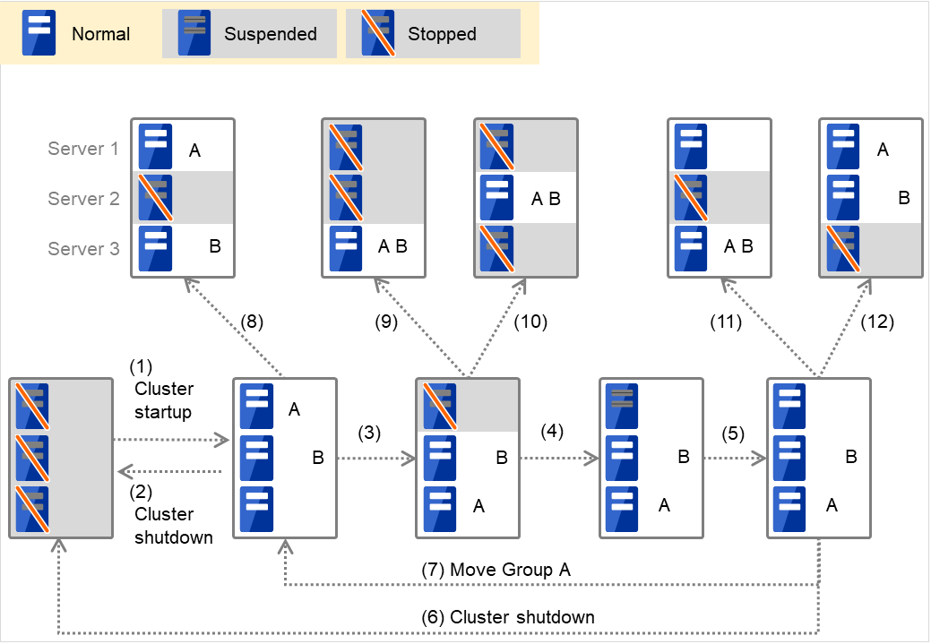
Fig. 3.1 Servers' statuses, and servers on which Groups A and B are started up
Cluster startup
Cluster shutdown
Failure of Server 1: Fails over to the next priority server.
Server1 power on
Server1 cluster recovery
Cluster shutdown
Move Group A
Failure of Server 2: Fails over to the next priority server.
Failure of Server 2: Fails over to the next priority server.
Failure of Server 3: Fails over to the next priority server
Failure of Server 2: Fails over to the next priority server.
Failure of Server 2: Fails over to the next priority server.
When Group A and B belong to the exclusion rules in which the exclusive attribute is set to Normal:
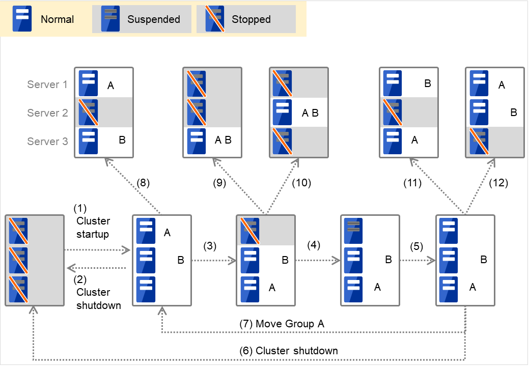
Fig. 3.2 Servers' statuses, and servers on which Groups A and B (normal exclusive groups) are started up
Cluster startup
Cluster shutdown
Failure of Server 1: Fails over to a server where no normal exclusive group is active.
Server1 power on
Server1 cluster recovery
Cluster shutdown
Move group A
Failure of Server 2: Fails over to a server where a normal exclusive group is not active.
Failure of Server 2: There is no server where a normal exclusive group is not active, but failover to the server because there is a server that can be started.
Failure of Server 3: There is no server where a normal exclusive group is not active, but failover to the server because there is a server that can be started.
Failure of Server 2: Fails over to a server where a normal exclusive group is not active.
Failure of Server 3: Fails over to a server where a normal exclusive group is not active.
When Group A and B belong to the exclusion rules in which the exclusive attribute is set to Absolute:

Fig. 3.3 Servers' statuses, and servers on which Groups A and B (absolute exclusive groups) are started up
Cluster startup
Cluster shutdown
Failure of Server 1: Fails over to the next priority server.
Server1 power on
Server1 cluster recovery
Cluster shutdown
Move group A
Failure of Server 2: Fails over to the next priority server.
Failure of Server 2: Does not failover (Group B stops).
Failure of Server 3: Does not failover (Group A stops).
Failure of Server 2: Fails over to the server where no absolute exclusive group is active.
Failure of Server 3: Fails over to the server where no absolute exclusive group is active.
- For Replicator - (two-server configuration) When Group A and B do not belong to the exclusion rules:
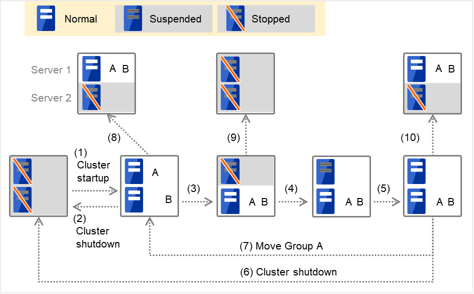
Fig. 3.4 Servers' statuses, and servers on which Groups A and B are started up (with Replicator)
Cluster startup
Cluster shutdown
Failure of Server 1: Fails over to the standby server of Group A.
Server1 power on
Server1 cluster recovery
Cluster shutdown
Move group A
Failure of Server 2: Fails over to the standby server of Group B.
Failure of Server 2
Failure of Server 2: Fails over to the standby server.
3.2.4. Operations at detection of activation and deactivation failure
When an activation or deactivation error is detected, the following operations are performed:
When an error in activation of group resources is detected:
When an error in activation of group resources is detected, activation is retried.
W hen activation retries fail as many times as the number set to Retry Count at Activation Failure, a failover to the server specified in Failover destination takes place.
If the failover fails as many times as the number set to Failover Threshold, the action configured in Final Action is performed.
When an error in deactivation of group resources is detected:
When an error in deactivation of group resources is detected, deactivation is retried.
When deactivation retries fail as many times as the number set to Retry Count at Deactivation Failure, the action configured in Final Action is performed.
Note
The following describes how an error in activation of group resources is detected:
When the following settings are made: (Failover Count Method: Server)

Fig. 3.5 Flow of operation on detecting a group resource activation failure (Failover Count Method: Server) (1)
The activation of Disk resource 1 fails due to a mounting error for a disk path failure or another cause.
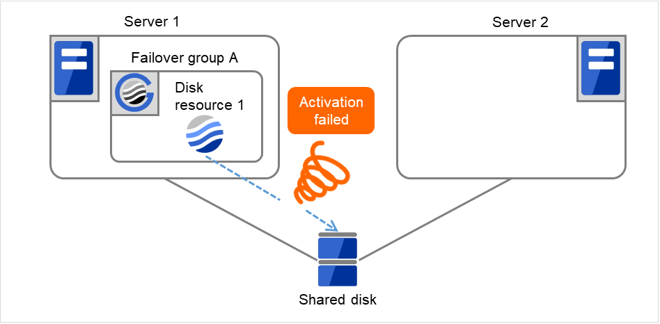
Fig. 3.6 Flow of operation on detecting a group resource activation failure (Failover Count Method: Server) (2)
The activation of Disk resource 1 is retried up to three times (activation retry count).
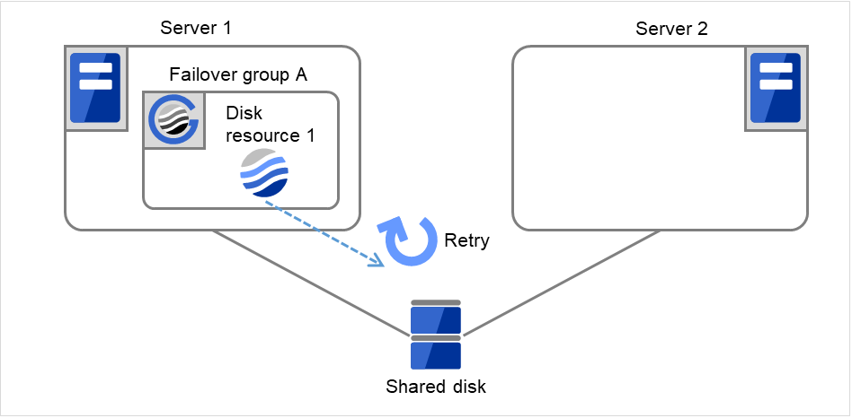
Fig. 3.7 Flow of operation on detecting a group resource activation failure (Failover Count Method: Server) (3)

Fig. 3.8 Flow of operation on detecting a group resource activation failure (Failover Count Method: Server) (4)

Fig. 3.9 Flow of operation on detecting a group resource activation failure (Failover Count Method: Server) (5)

Fig. 3.10 Flow of operation on detecting a group resource activation failure (Failover Count Method: Server) (6)
On Server 1, Disk resource 1 starts to be activated. If a failure occurs on the way, the activation is retried up to three times.
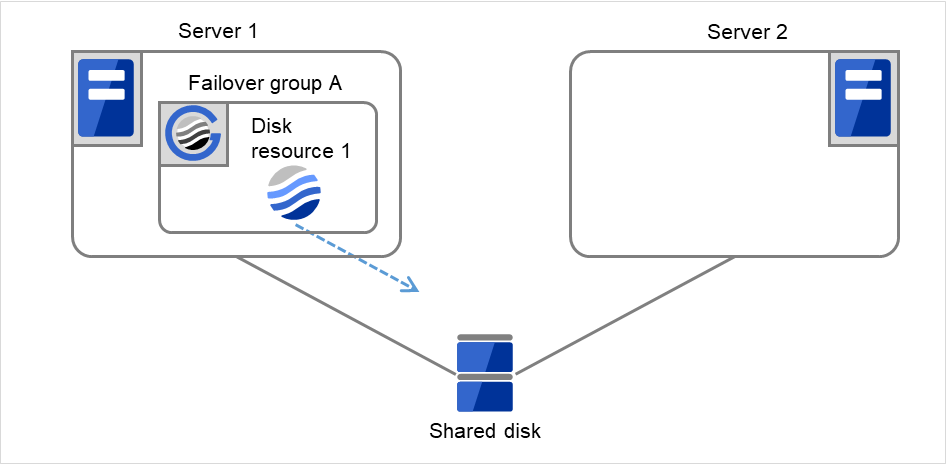
Fig. 3.11 Flow of operation on detecting a group resource activation failure (Failover Count Method: Server) (7)

Fig. 3.12 Flow of operation on detecting a group resource activation failure (Failover Count Method: Server) (8)
When the following settings are made: (Failover Count Method: Cluster)
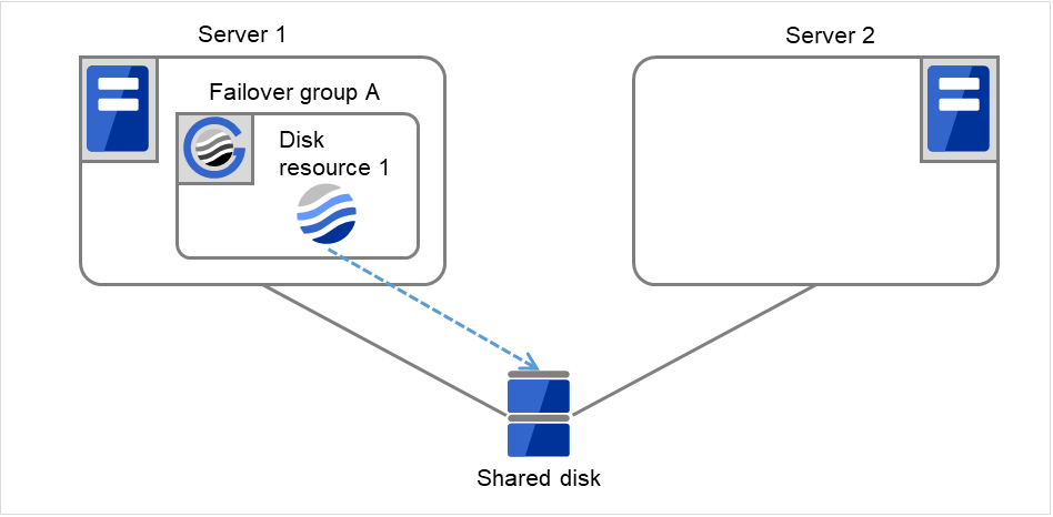
Fig. 3.13 Flow of operation on detecting a group resource activation failure (Failover Count Method: Cluster) (1)
The activation of Disk resource 1 fails due to a mounting error for a disk path failure or another cause.

Fig. 3.14 Flow of operation on detecting a group resource activation failure (Failover Count Method: Cluster) (2)
The activation of Disk resource 1 is retried up to three times (activation retry count).

Fig. 3.15 Flow of operation on detecting a group resource activation failure (Failover Count Method: Cluster) (3)
Failover group A starts to be failed over. Failover Threshold represents how many times failover is performed on each server. This is the first failover on this cluster.

Fig. 3.16 Flow of operation on detecting a group resource activation failure (Failover Count Method: Cluster) (4)
Disk resource 1 starts to be activated (e.g. for mounting the file system). If a failure occurs on the way, the activation is retried up to three times.

Fig. 3.17 Flow of operation on detecting a group resource activation failure (Failover Count Method: Cluster) (5)
If the specified retry count is exceeded for the activation of Disk resource 1 on Server 2 as well, Failover group A starts to be failed over. This is the second failover on this cluster.
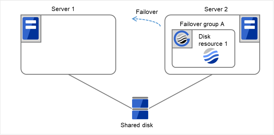
Fig. 3.18 Flow of operation on detecting a group resource activation failure (Failover Count Method: Cluster) (6)
On Server 1, Disk resource 1 starts to be activated. If a failure occurs on the way, the activation is retried up to three times.

Fig. 3.19 Flow of operation on detecting a group resource activation failure (Failover Count Method: Cluster) (7)
If the specified retry count is exceeded for the activation of Disk resource 1 on Server 1 as well, the specified Final Action is started. No failover is performed then, because Failover Threshold is set at 2. Final Action means the action to be taken after the specified failover retry count is exceeded. Here, Failover group A starts to be stopped.
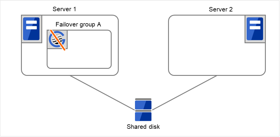
Fig. 3.20 Flow of operation on detecting a group resource activation failure (Failover Count Method: Cluster) (8)
3.2.5. Final action
When activation fails even though the failover performed as many times as the number set to Failover Threshold, the action configured in Final Action is performed. The final action can be selected from the following operations.
- No Operation (Activate next resource)Continues the group start process.
- No Operation (Not activate next resource)Cancels the group start process.
- Stop GroupDeactivates all resources in the group which the group resource that an activation error is detected belongs.
- Stop cluster serviceStops the EXPRESSCLUSTER Server service of the server that an activation error is detected.
- Stop the cluster service and shutdown OSStops the EXPRESSCLUSTER Server service of the server that an activation error is detected, and shuts down the OS.
- Stop cluster service and reboot OSStops the EXPRESSCLUSTER Server service of the server that an activation error is detected, and reboots the OS.
- Generating of intentional Stop ErrorGenerate a stop error intentionally on the server that an activation error is detected.
3.2.6. Script before final action
When a group resource activation error is detected, a script before final action can be executed before the last action during detection of a deactivation error.
Environment variables used with a script before final action
When executing a script, EXPRESSCLUSTER sets information such as the state in which it is executed (when an activation error occurs, when a deactivation error occurs) in the environment variables.
Environment variable |
Value |
Description |
|---|---|---|
CLP_TIMING
...Execution timing
|
START |
Executes a script before final action in the event of a group resource activation error. |
STOP |
Executes a script before final action in the event of a group resource deactivation error. |
|
CLP_GROUPNAME
...Group name
|
Group name |
Indicates the name of the group containing the group resource in which an error that causes the script before final action to be executed is detected. |
CLP_RESOURCENAME
...Group resource name
|
Group resource name |
Indicates the name of the group resource in which an error that causes the script before final action to be executed is detected. |
Flow used to describe a script before final action
The following explains the environment variables in the previous topic and an actual script, associating them with each other.
Example of a script before final action in the event of an deactivation error
rem ********************************************
rem *            predeactaction.bat            *
rem ********************************************

echo START

rem Refer to the environment variable of the script execution factor
rem to determine the subsequent process.
IF "%CLP_TIMING%"=="STOP" GOTO NORMAL

rem ********************************************
rem CLP_TIMING is not STOP (Error)
rem ********************************************
echo NO_CLP
GOTO EXIT

rem ********************************************
rem CLP_TIMING is STOP
rem ********************************************
:NORMAL
echo %CLP_GROUPNAME%
echo %CLP_RESOURCENAME%

rem Here, write a recovery process to be performed.

:EXIT
echo EXIT
Tips for creating a script before final action
Using clplogcmd, you can output messages to the Alert logs of Cluster WebUI.
Notes on script before final action
- Condition that a script before final action is executedA script before final action is executed before the final action upon detection of a group resource activation or deactivation failure. Even if No operation (Next Resources Are Activated/Deactivated) or No operation (Next Resources Are Not Activated/Deactivated) is set as the final action, a script before final action is executed.If the final action is not executed because the maximum restart count has reached the upper limit or by the function to suppress the final action when all other servers are being stopped, a script before final action is not executed.
3.2.7. Script Before and After Activation/Deactivation
An arbitrary script can be executed before and after activation/deactivation of group resources.
Environment variables used with a script after activation/deactivation
When executing a script, EXPRESSCLUSTER sets information such as the state in which it is executed (before activation, after activation, before deactivation, or after deactivation) in the environment variables.
Environment variable |
Value |
Description |
|---|---|---|
CLP_TIMING
...Execution timing
|
PRESTART |
Executes a script before a group resource is activated. |
POSTSTART |
Executes a script after a group resource is activated. |
|
PRESTOP |
Executes a script before a group resource is deactivated. |
|
POSTSTOP |
Executes a script after a group resource is deactivated. |
|
CLP_GROUPNAME
...Group name
|
Group name |
Indicates the group name of the group resource containing the script. |
CLP_RESOURCENAME
...Group resource name
|
Group resource name |
Indicates the name of the group resource containing the script. |
Flow used to describe a script before and after activation/deactivation
The following explains the environment variables in the previous topic and an actual script, associating them with each other.
Example of a script before and after activation/deactivation
rem ******************************************************
rem *                    rscextent.bat                   *
rem ******************************************************

echo START
IF "%CLP_TIMING%"=="PRESTART" GOTO PRESTART
IF "%CLP_TIMING%"=="POSTSTART" GOTO POSTSTART
IF "%CLP_TIMING%"=="PRESTOP" GOTO PRESTOP
IF "%CLP_TIMING%"=="POSTSTOP" GOTO POSTSTOP

:PRESTART
echo %CLP_GROUPNAME%
echo %CLP_RESOURCENAME%
rem Here, write any process to be performed before the resource activation.
rem

GOTO EXIT

:POSTSTART
echo %CLP_GROUPNAME%
echo %CLP_RESOURCENAME%
rem Here, write any process to be performed after the resource activation.
rem

GOTO EXIT

:PRESTOP
echo %CLP_GROUPNAME%
echo %CLP_RESOURCENAME%
rem Here, write any process to be performed before the resource deactivation.
rem

GOTO EXIT

:POSTSTOP
echo %CLP_GROUPNAME%
echo %CLP_RESOURCENAME%
rem Here, write any process to be performed after the resource deactivation.
rem

GOTO EXIT

:EXIT
Tips for creating a script before and after activation/deactivation
Using clplogcmd, you can output messages to the Alert logs of Cluster WebUI.
Notes on script before and after activation/deactivation
None.
3.2.8. Reboot count limit
If Stop cluster service and shutdown OS or Stop cluster service and reboot OS is selected as the final action to be taken when any error in activation or deactivation is detected, you can limit the number of shutdowns or reboots caused by detection of activation or deactivation errors.
This maximum reboot count is the upper limit of reboot count of each server.
Note
The following describes the flow of operations when the limitation of reboot count is set as shown below:
As a final action, Stop cluster service and reboot OS is executed once because the maximum reboot count is set to one (1).
If the EXPRESSCLUSTER Server service is started successfully after rebooting OS, the reboot count is reset after 10 minutes because the time to reset maximum reboot count is set to 10 minutes.
Setting example

Fig. 3.21 Process with the limited number of reboots (1)
Server 1
Server 2
Maximum reboot count
1
1
Reboot count
0
0
The activation of Disk resource 1 fails.

Fig. 3.22 Process with the limited number of reboots (2)
Server 1
Server 2
Maximum reboot count
1
1
Reboot count
0
0
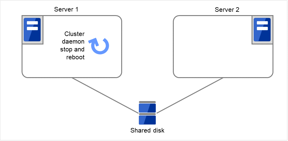
Fig. 3.23 Process with the limited number of reboots (3)
Server 1
Server 2
Maximum reboot count
1
1
Reboot count
1
0
Failover group A starts to be failed over.
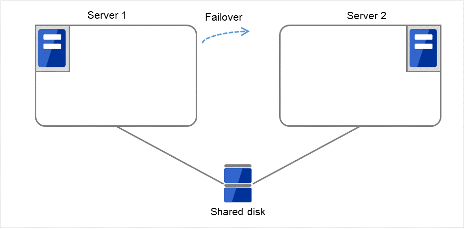
Fig. 3.24 Process with the limited number of reboots (4)
Server 1
Server 2
Maximum reboot count
1
1
Reboot count
1
0
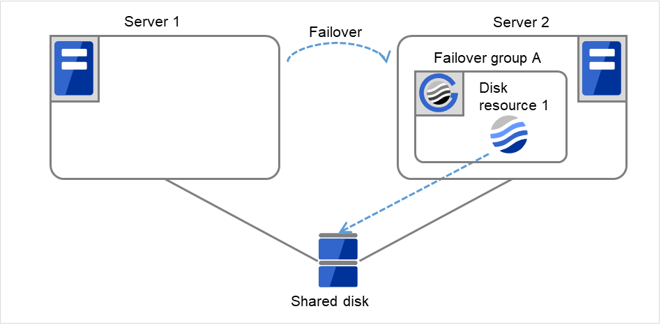
Fig. 3.25 Process with the limited number of reboots (5)
Server 1
Server 2
Maximum reboot count
1
1
Reboot count
1
0
Start the failover of Failover group A by using the clpgrp command or Cluster WebUI.

Fig. 3.26 Process with the limited number of reboots (6)
Server 1
Server 2
Maximum reboot count
1
1
Reboot count
1
0
Disk resource 1 starts to be activated (e.g. for mounting the file system).
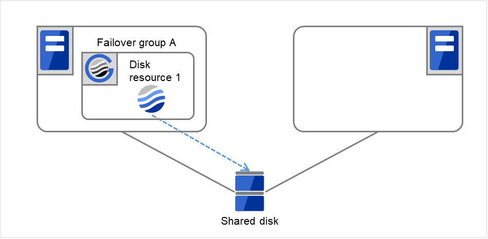
Fig. 3.27 Process with the limited number of reboots (7)
Server 1
Server 2
Maximum reboot count
1
1
Reboot count
1
0

Fig. 3.28 Process with the limited number of reboots (8)
Server 1
Server 2
Maximum reboot count
1
1
Reboot count
1
0
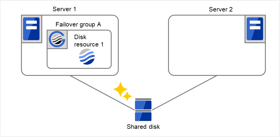
Fig. 3.29 Process with the limited number of reboots (9)
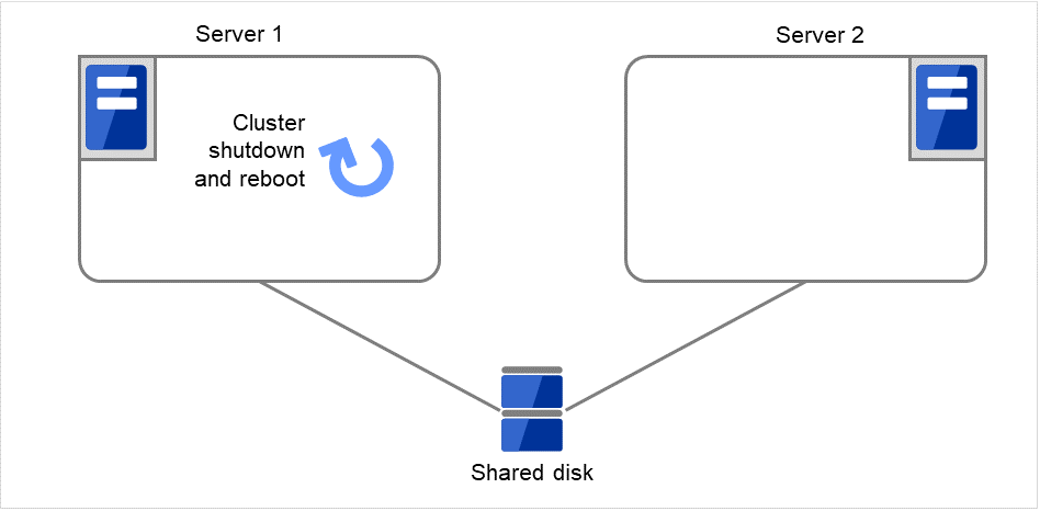
Fig. 3.30 Process with the limited number of reboots (10)
Server 1
Server 2
Maximum reboot count
1
1
Reboot count
1
0

Fig. 3.31 Process with the limited number of reboots (11)
Server 1
Server 2
Maximum reboot count
1
1
Reboot count
0
0
3.2.9. Resetting the reboot count
Run the clpregctrl command to reset the reboot count. For details on the clpregctrl command, see "Controlling reboot count (clpregctrl command)" in "8. EXPRESSCLUSTER command reference" in this guide.
3.2.10. Checking a double activation
When a group is started, it is possible to check whether a double activation will occur or not.
If a double activation is determined not to occur:
A group startup begins.
If a double activation is determined to occur (if a timeout occurs):
A group startup does not begin. If the server attempts to start up the group, that group is stopped.
Note
If a single resource is started while its relevant group is stopped, a double activation check will be performed. However, if a single resource is started while any resource in the group is activated, a double activation check will not be performed.
If there are no floating IP resources for the group for which Execute Multi-Failover-Service Check is selected, a double activation is not executed and the group startup begins.
If a double activation is determined to occur, the statuses of groups and resources may not match among servers.
3.2.11. Understanding setting of group start dependence and group stop dependence
You can set the group start and stop order by setting group start dependence and group stop dependence.
When group start dependence is set:
For group start, start processing of this group is performed after start processing of the group subject to start dependence completes normally.
For group start, if a timeout occurs in the group for which start dependence is set, the group does not start.
When group stop dependence is set:
For group stop, stop processing of this group is performed after stop processing of the group subject to stop dependence completes normally.
If a timeout occurs in the group for which stop dependence is set, the group stop processing continues.
Stop dependence is performed according to the conditions specified in Cluster WebUI.
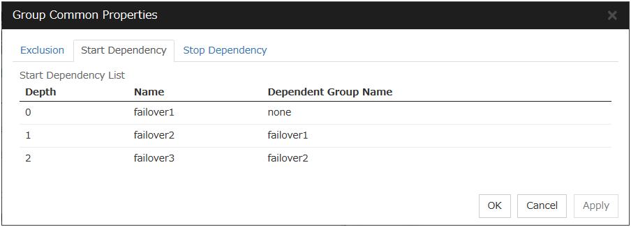
To display the settings made for group start dependence and group stop dependence, click Group properties in the config mode of Cluster WebUI and then click the Start Dependency tab and the Stop Dependency tab.Depths for group start dependence are listed below as an example.The following explains group start execution using examples of simple status transition.


Fig. 3.32 Order of starting groups
Group A Server 1
Group B Server 2
Group C Server 1 -> Server 2
Group start dependence setting
Group A Start dependence is not set.
Group B Start dependence is not set.
Group C Group A start dependence is set.
Start dependence is set when Group C is started by the server of Group B.
When Server 1 starts Group A and Group C
Server 1 starts Group C after Group A has been started normally.
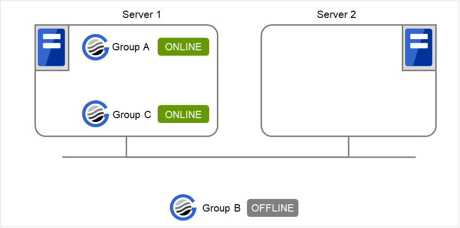
Fig. 3.33 Server 1 starts Group A and Group C
When Server 1 starts Group A and Server 2 starts Group C
Server 2 starts Group C after Server 1 has started Group A normally.
Wait Only when on the Same Server is not set, so Group A start dependence by another server is applied.
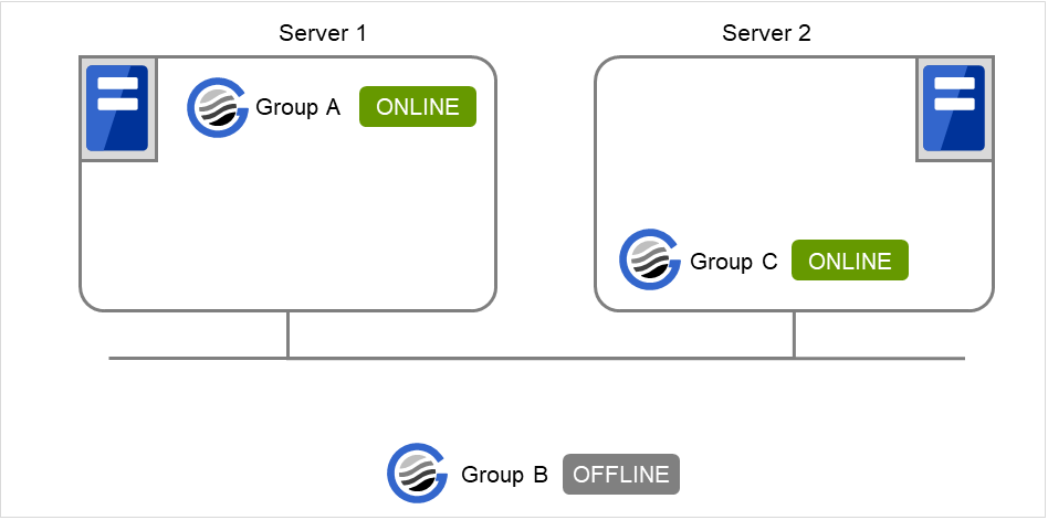
Fig. 3.34 Server 1 starts Group A and Server 2 starts Group C
When Server 1 starts Group C and Server 2 starts Group B
Server 1 starts Group C without waiting for the normal start of Group B. Group C is set to wait for Group B start only when it is started by the same server. However, start dependence is not applied to Group C because Group B is set such that it is not started by Server 1.
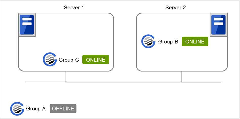
Fig. 3.35 Server 1 starts Group C and Server 2 starts Group B
When Server 1 starts Group A and Group C
If Server 1 fails in Group A start, Group C is not started.
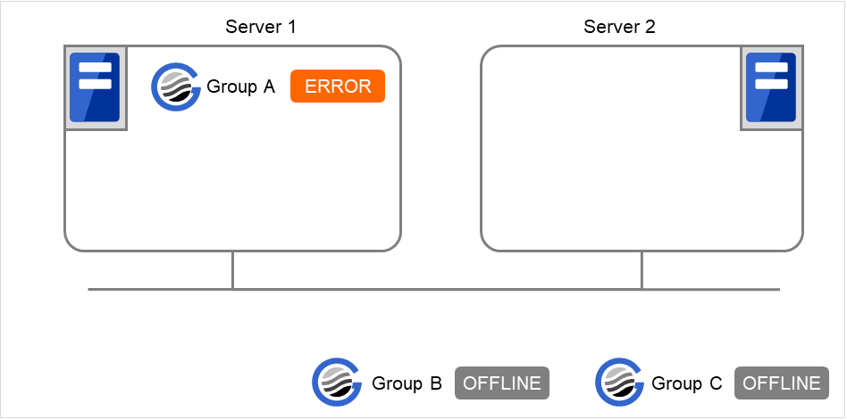
Fig. 3.36 Failing in starting Group A, Server 1 does not start Group C
When Server 1 starts Group A and Group C
If Server 1 fails in Group A start and a failover occurs in Server 2 due to Group A resource recovery, Server 2 starts Group A and then Server 1 starts Group C.
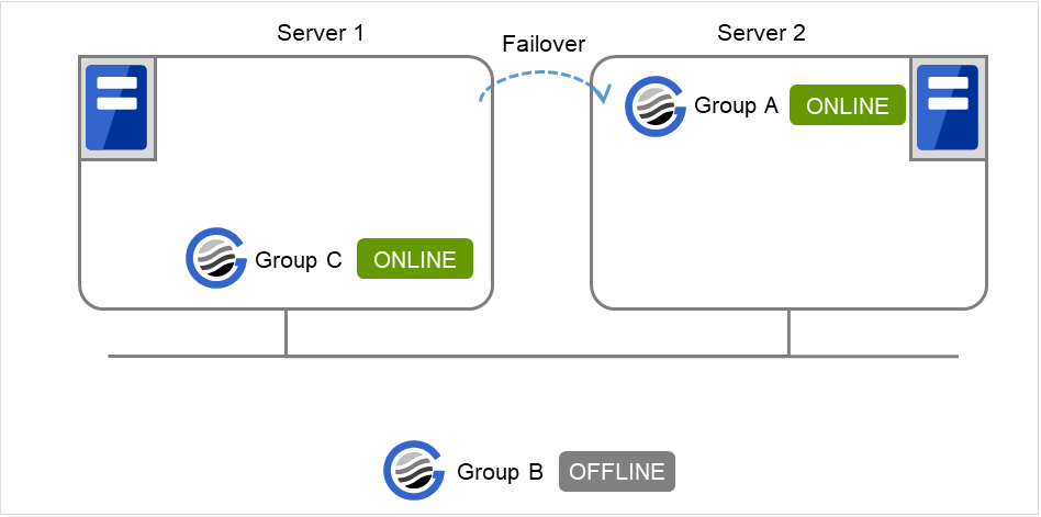
Fig. 3.37 GroupA fails over to Server 2, and Group C is started on Server 1
When Server 1 starts Group A and Group C
If a Group A start dependence timeout occurs on Server 1, Group C is not started.
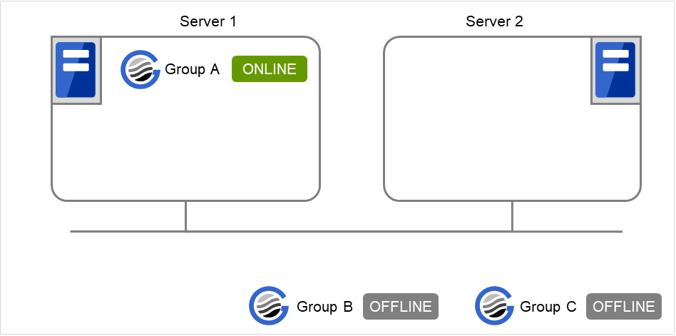
Fig. 3.38 Server 1 starts Group A
When Server 1 starts only Group C
Server 1 has not started Group A, so a start dependence timeout occurs. If this timeout occurs, Group C is not started.
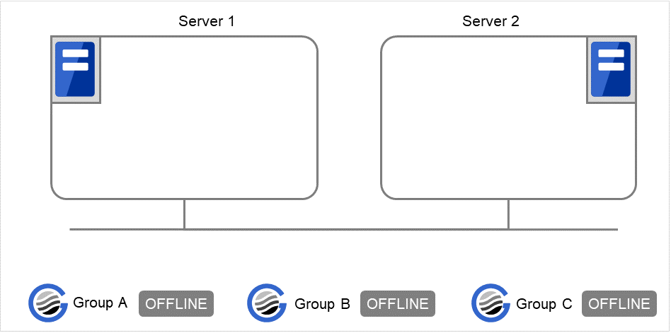
Fig. 3.39 Server 1 does not start Group A or Group C
Note
When a group is started, there is no function to automatically start the group for which start dependence is set.
The group is not started if a timeout occurs in the group for which start dependence is set.
The group is not started if the group for which start dependence is set fails to start.
If the group for which start dependence is set has both a normally started resource and a stopped resource, the group is judged to have already been normally started.
When a group is stopped, there is no function to automatically stop the group for which stop dependence is set.
Group stop processing continues if a timeout occurs in a group for which stop dependence is set.
Group stop processing continues if a group for which stop dependence is set fails to stop.
The group stop processing or resource stop processing by the Cluster WebUI or clpgrp command does not apply stop dependence. Stop dependence is applied according to the setting (when the cluster or a server stops) made with the Cluster WebUI.
At the timing of a failover, if a start waiting timeout occurs, the failover fails
3.2.12. Understanding Exclusive Control of Group
The Failover exclusive attributes set exclusive attributes of the group at failover. However, they cannot set any attribute under the following conditions:
If Virtual machine group is specified as the group type
When failover attribute is one of Fail over dynamically, Prioritize failover policy in the server group or Enable only manual failover among the server groups.
The settable failover exclusive attributes are as follows:
Off
Exclusion is not performed at failover. Failover is performed on the server of the highest priority among the servers that can fail over.
Normal
Exclusion is performed at failover. Failover is performed on the server on which the other normal exclusion groups are not started and which is given the highest priority among the servers that can run the group.However, if the other normal exclusion groups have already been started on all servers that the failover can be performed, exclusion is not performed. Failover is performed on the server that is given the highest priority among the servers on which failover can be performed.
Absolute
Exclusion is performed at failover. Failover is performed on the server on which the other absolute exclusion groups are not started and which is given the highest priority among the servers that can run the group.However, failover is not performed if the other absolute exclusion groups have already been started on all servers on which failover can be performed.Note
Exclusion is not performed to the groups with different exclusion rules. Exclusive control is performed only among the groups with the same exclusion rule, according to the set exclusion attribute. In either case, exclusion is not performed with the no-exclusion group. For details on the failover exclusive attribute, see " Understanding failover policy ". Furthermore, for details on the settings of the exclusion rules, see " Group common properties ".
3.2.13. Understanding server groups
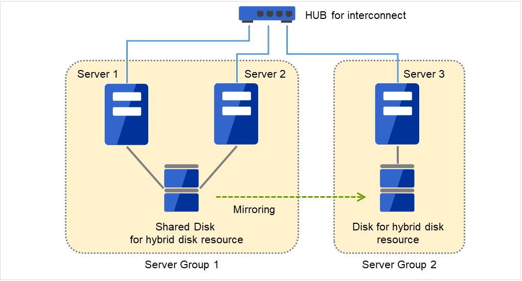
Fig. 3.40 Server groups
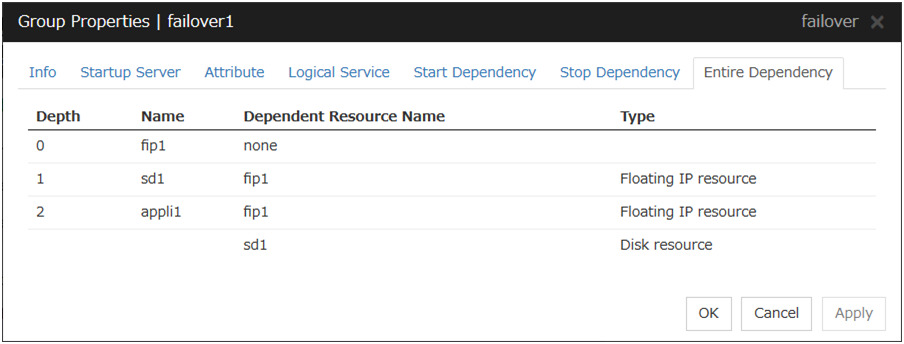
3.2.14. Understanding the settings of dependency among group resources
By specifying dependency among group resources, you can specify the order of activating them.
When the dependency among group resources is set:
When activating a failover group that a group resource belongs to, its activation starts after the activation of the Dependent Resources is completed.
When deactivating a group resource, the deactivation of the "Dependent Resources" starts after the deactivation of the group resource is completed.
The following shows an example of the depth of dependency of resources that belong to a group.
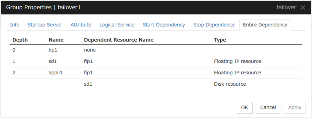

Fig. 3.41 Example of a group resource activation order

Fig. 3.42 Example of a group resource deactivation order
3.2.15. Setting group resources for individual server

Server Individual Setup
Parameters that can be set for individual servers on a floating IP resource are displayed.
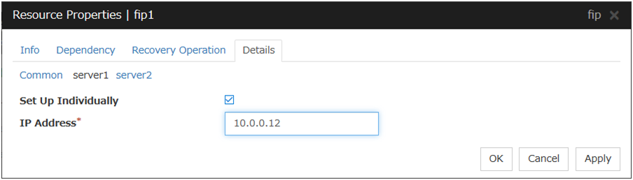
Set Up Individually
Click the tab of the server on which you want to configure the server individual setting, and select this check box. The boxes for parameters that can be configured for individual servers become active. Enter required parameters.
Note
When setting up a server individually, you cannot select Tuning.
3.3. Group common properties
3.3.1. Exclusion tab
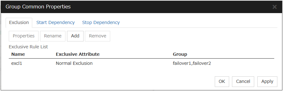
Add
Add exclusion rules. Select Add to display the Exclusive Rule Definition dialog box.
Remove
Remove exclusion rules.
Rename
The change server group name dialog box of the selected exclusion rule is displayed.]
There are the following naming rules.
Up to 31 characters (31 bytes).
Names cannot start or end with a hyphen (-) or a space.
A name consisting of only numbers is not allowed.
Names should be unique (case-insensitive) in the exclusion rule.

Properties
Display the properties of the selected exclusion rule.
Exclusive Rule Definition
The name of the exclusion rule and the exclusive attribute are set. Either Normal or Absolute can be set for an exclusive attribute. Normal can be set just one time, whereas Absolute can be set more than one time. If an exclusion rule in which Normal is set already exists, Normal cannot be set any more.

Name
Display the exclusion rule name.
Exclusive Attribute
Display the exclusive attribute set in the exclusion rule.
Group
Display the list of failover group names which belong to the exclusion rule.
After selecting a group which you want to register into the exclusion rule from Available Group, press Add.
Exclusive Group displays groups registered into the exclusion rule. A failover group added in another exclusion rule is not displayed on Available Group.
3.4. Group properties
3.4.1. Resources tab

3.4.2. Info tab
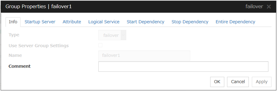
Type
The group type is displayed.
Use Server Group Settings
Name
The group name is displayed.
Comment (Within 127 bytes)
Enter a comment for the group. Use only one-byte alphabets and numbers.
3.4.3. Startup Server tab
There are two types of settings for the server that starts up the group: starting up the group on all servers or on only the specified servers and server groups that can run the group.
If the setting on which the group is started up by all the servers is configured, all the servers in a cluster can start a group. The group startup priority of servers is same as the one of servers. For details on the server priority, see "Master Server tab" in "Servers Properties" in "2. Parameter details" in this guide.
When selecting servers and server groups that can run the group, you can select any server or server group from those registered to the cluster. You can also change the startup priority of servers and server groups that can run the group.
To set the server to start up the failover group:

Failover is possible on all servers
Specify the server that starts a group.
Add
Use this button to add a server. Select a server that you want to add from Available Servers, and then click Add. The server is added to Servers that can run the Group.
Remove
Use this button to remove a server. Select a server that you want to remove from Servers that can run the Group, and then click Remove. The server is added to Available Servers.
Order
Use these buttons to change the priority of the servers that can be started. Select a server whose priority you want to change from Servers that can run the Group. Click the arrows to move the selected row upward or downward.
To use the server group settings:
In case of the group including the hybrid disk resource, it is necessary to configure the server that can run a group using the server group settings. For server group settings, see "Server Group tab" in "Servers Properties" in "2. Parameter details" in this guide.
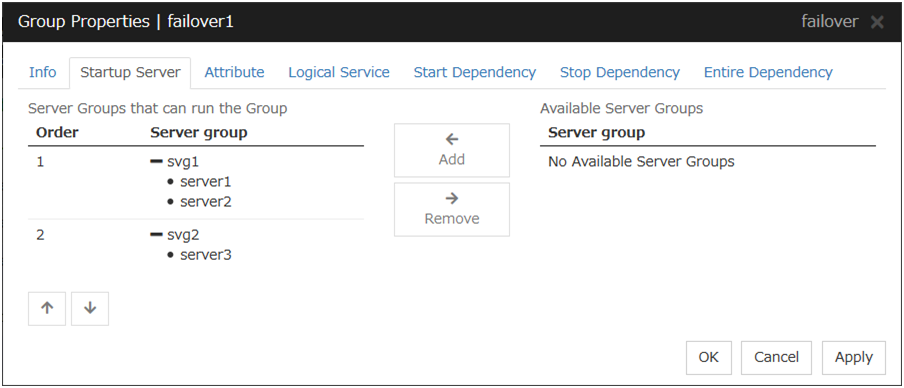
Add
Use this button to add a server group to server groups you use. Select a server group that you want to add from Available Server Groups, and then click Add. The server group is added to Server Groups that can run the Group.
Remove
Use this button to remove a server group from server groups you use. Select a server group that you want to remove from Available Server Groups, and then click Remove. The server is added to Server Groups that can run the Group.
Order
Use these buttons to change the priority of the server groups that can run a group. Select a server groups whose priority you want to change from Server Groups that can run the Group. Click the arrows to move the selected row upward or downward.
3.4.4. Attribute tab
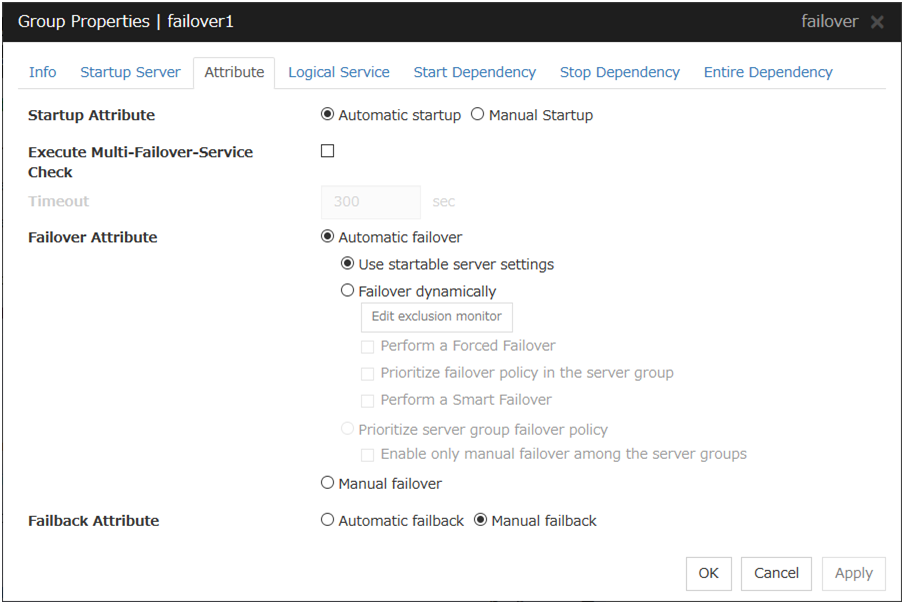
Startup Attribute
Select whether to automatically start the group from EXPRESSCLUSTER (auto startup), or to manually start from the Cluster WebUI or by using the clpgrp command (manual startup) at the cluster startup.
Execute Multi-Failover-Service Check
Check whether a double activation will occur or not before a group is started.
Timeout (1 to 9999)
Specify the maximum time to be taken to check a double activation. The default value is set as 300 seconds. Specify a larger value than the one set for Ping Timeout of Floating IP Resource Tuning Properties for the floating IP resource that belongs to the group.
Failover Attribute
Select if the failover is performed automatically when server fails.
Failback Attribute
Select if the failback is performed automatically to the group when a server that has a higher priority than other server where the group is active is started. For groups that have mirror disk resources or hybrid disk resources, select manual failback.
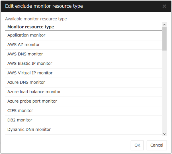
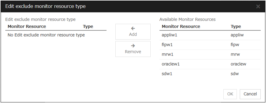
Edit Exclusion Monitor
Dynamic failover excludes the server for which the monitor resource has detected an error, from the failover destinations. If Failover dynamically is selected as the failover attribute, you can set the monitor resource to be excluded.
The exclusive monitor can be set with the monitor resource type and monitor resource name.
Adds the selected monitor resource type.
Add
Adds the monitor resource selected from Available Monitor Resources list to Edit exclude monitor resource type.
Remove
Removes the monitor resource selected with Edit exclude monitor resource type, from the list.
Note
The following monitor resource types cannot be registered for the exclusive monitor resource type. Moreover, a resource name cannot be registered for the exclusive monitor resource group.
Hybrid disk monitor
Mirror disk connect monitor
Note
The monitor resource in the warning status is not handled as being abnormal. However, the mirror disk monitor resource is excluded.The monitor resource set for monitoring at activation does not enter the abnormal status because it does not perform monitoring for a server other than the group start server.The monitor resource stopped with the Cluster WebUI or clpmonctrl command enters the normal status.A server that has not been set to monitor a monitor resource does not enter the abnormal status because it does not perform monitoring.Note
For the mirror disk monitor resource, any abnormality is determined from whether the mirror disk resource can be activated. This determination does not depend on the status of the mirror disk monitor resource.Even if the mirror disk monitor resource is in the abnormal status, the server on which the mirror disk resource can be activated normally is not excluded from the failover destinations.Even if the mirror disk monitor resource is in the normal or warning status, any server on which the mirror disk resource cannot be activated normally is excluded from the failover destinations.Before the initial mirror configuration, the failover group may fail to start. It is recommended that the mirror disk monitor resource be registered in the exclusive monitor after the initial mirror configuration.

3.4.5. Logical Service tab
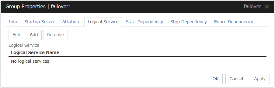
Add
Use this button to add a logical service to the Logical Service.Up to 48 logical service names can be registered within the failover group. The same logical service name can be registered multiple times as long as it is registered with different failover groups.
Remove
Use this button to delete the selected logical service name from the Logical Service.
Edit
Use this button to display the Enter the logical service name dialog box.

Logical Service Name (Within 31 bytes)
Enter the Logical Service Name that you want to add within 31 bytes.For details on the logical service, see "What is a group?".
3.4.6. Start Dependency tab
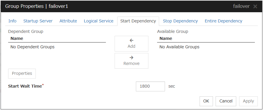
Add
Clicking Add adds the group selected from Available Group to Dependent Group.
Remove
Clicking Remove removes the group selected from Dependent Group.
Start Wait Time (0 to 9999)
Specify how many seconds to wait before a timeout occurs in the target group start processing. The default value is 1800 seconds.
Property
Clicking Property changes the properties of the group selected from Dependent Group.

Wait Only when on the Same Server
Specify whether to wait for starting only if the group for which start waiting is specified and the target group are starting on the same server.If the server on which the group with start waiting specified starts is not included as the Startup Server of the target group, waiting is not required.If a target group fails to start on a server other than the server on which the group with start waiting specified is starting, waiting is not required.
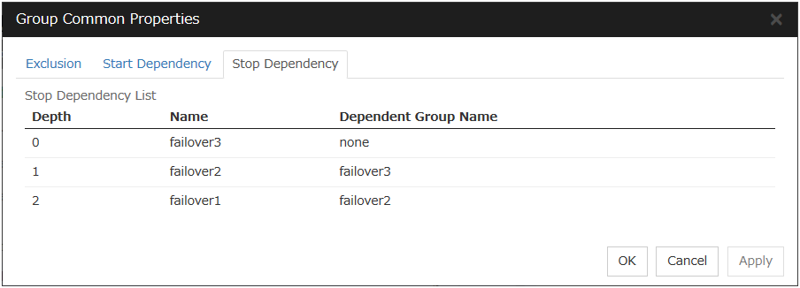
3.4.7. Stop Dependency
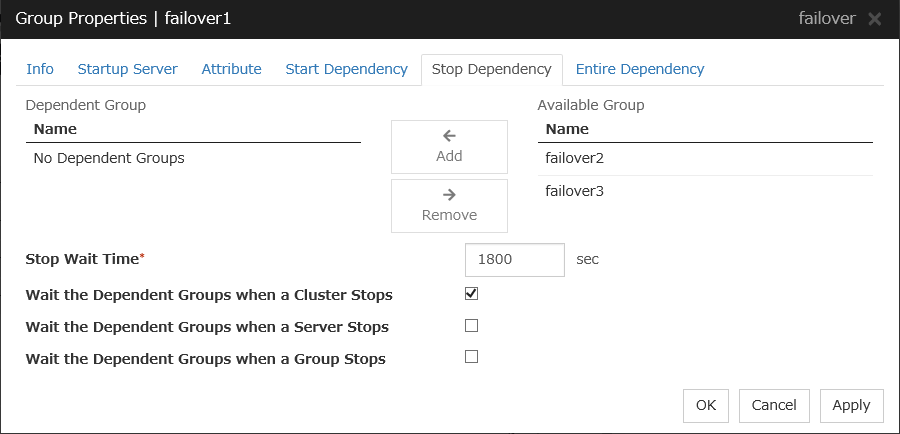
Add
Clicking Add adds the group selected from Available Group to Dependent Group.
Remove
Clicking Remove removes the group selected from Dependent Group.
Stop Wait Time (0 to 9999)
Specify how many seconds to wait before a timeout occurs in the target group stop processing. The default value is 1800 seconds.
Wait the Dependent Groups when a Cluster Stops
Specify whether to wait for the dependent groups to stop when the cluster stops.
Wait the Dependent Groups when a Server Stops
Specify whether to wait for the dependent groups to stop when a single server stops. This option waits for the stop of only those groups running on the same server, among all the dependent groups.
Wait the Dependent Groups when a Group Stops
Specify whether to wait for the dependent groups to stop when the groups are being stopped. This option waits for the stop of only those groups running on the same server, among all the dependent groups.
3.4.8. Entire Dependency
Displays the settings of dependency among group resources.
3.5. Resource Properties
3.5.1. Info tab
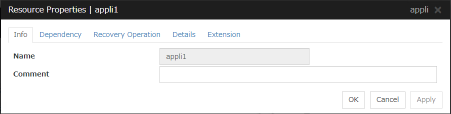
Name
The resource name is displayed.
Comment (Within 127 bytes)
Enter a comment for the resource. Use only one-byte alphabets and numbers.
3.5.2. Dependency tab
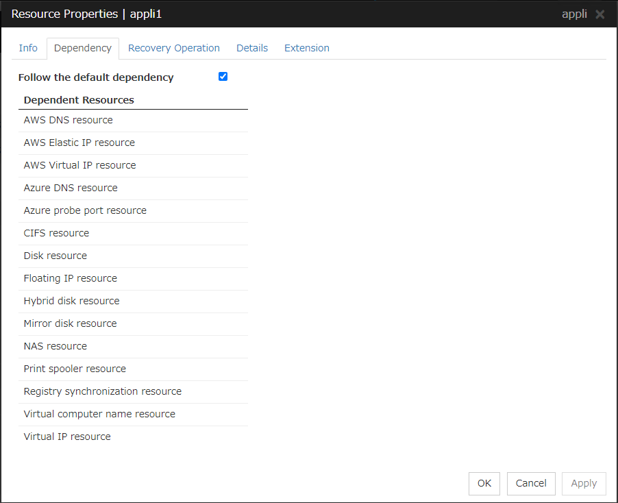
Follow the default dependence
Select if the selected group resource follows the default EXPRESSCLUSTER dependency.

Add
It is used when adding the group resource selected in Available Resources to Dependent Resources.
Remove
It is used when removing the group resource selected in Dependent Resources from Dependent Resources.
3.5.3. Recovery Operation tab
When an error in activation of the group resource is detected:
When an error is detected while activating the group resource, try activating it again.
When the activation retry count exceeds the number of times set in Retry Count, failover to the server specified in the Failover Target Server is executed.
When the group resource cannot be activated even after executing a failover as many times as specified in Failover Threshold, the final action is taken.
When an error in deactivation of the group resource is detected:
When an error is detected while deactivating the group resource, try deactivating it again.
When the deactivation retry count exceeds the number of times set in Retry Count at Deactivation Failure, the final action is taken.
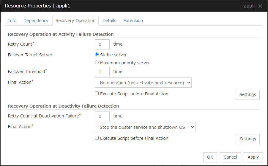
Recovery Operation at Activation Failure Detection
Retry Count (0 to 99)
Enter how many times to retry activation when an activation error is detected. If you set this to zero (0), the activation will not be retried.
Failover Target Server
Select a Failover Target Server for the failover that takes place after activation retries upon activation error detection have failed for the number of times specified in Retry Count.
Failover Threshold (0 to 99)
Enter how many times to retry failover after activation retry fails as many times as the number of times set in Retry Count when an error in activation is detected.
If you set this to zero (0), failover will not be executed.
When Server is selected for Failover Count Method on the Extension tab in the Cluster Properties, specify any number (0 to 99) for the failover threshold count.
When Cluster is selected for Failover Count Method on the Extension tab in the Cluster Properties, configure the following settings for the failover threshold count.
For the settings of Failover Count Method, refer to "Extension Tab" in "Cluster properties" in "2. Parameter details" in this guide.
Final Action
Select an action to be taken when activation retry failed the number of times specified in Retry Count and failover failed as many times as the number of times specified in Failover Threshold when an activation error is detected.
Select a final action from the following:
No Operation (Activate next resource)
No Operation (Not activate next resource)
Stop Group
Stop cluster service
Stop cluster service and shutdown OS
Stop cluster service and reboot OS
Generating of intentional Stop Error
For details on the final action, see "Final action".
Execute Script before Final Action
Select whether script is run or not before executing final action when an activation failure is detected.
Recovery Operation at Deactivation Failure Detection
Retry Count at Deactivation Failure (0 to 99)
Enter how many times to retry deactivation when an error in deactivation is detected.
If you set this to zero (0), deactivation will not be retried.
Final Action
Select the action to be taken when deactivation retry failed the number of times specified in Retry Count at Deactivation Failure when an error in deactivation is detected.
Select the final action from the following:
No Operation (Deactivate next resource)
No Operation (Not deactivate next resource)
Stop cluster service and shutdown OS
Stop cluster service and reboot OS
Generating of intentional Stop Error
For details on the final action, see "Final action".
Note
If you select No Operation as the final action when a deactivation error is detected, group does not stop but remains in the deactivation error status. Make sure not to set No Operation in the production environment.
Execute Script before Final Action
Select whether script is run or not before executing final action when a deactivation failure is detected.
3.5.4. Details tab
The parameters specific to each resource are described in its explanation part.
3.5.5. Extension tab
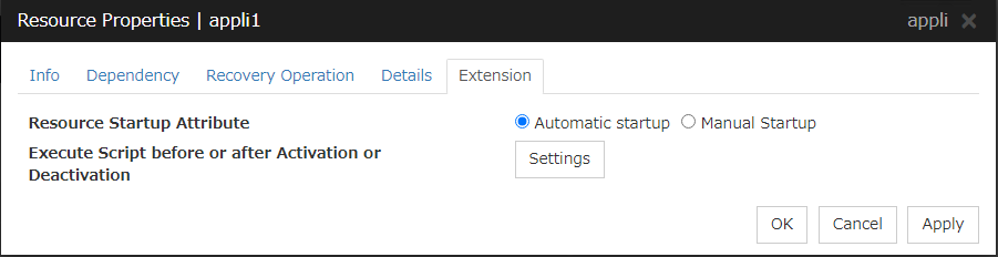
Resource Startup Attribute
Select whether to automatically start up the resource in starting up the group or manually (by using Cluster WebUI or the clprsc command).
Execute Script before or after Activation or Deactivation
Select whether script is run or not before and after activation/deactivation of group resources. To configure the script settings, click Script Settings.
The script can be run at the specified timing by selecting the checkbox.
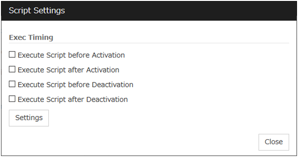
Exec Timing
Execute Script before Activation
Execute Script after Activation
Execute Script before Deactivation
Execute Script after Deactivation
To configure the script settings, click Settings.
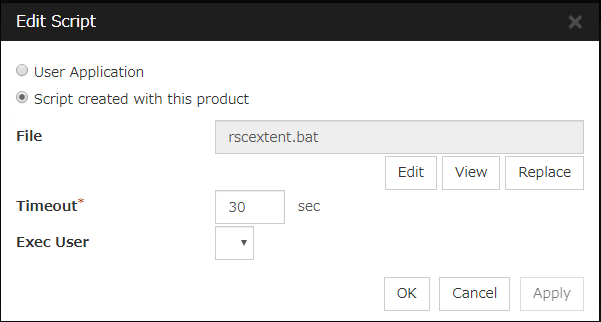
User Application
Use an executable file (executable batch file or execution file) on the server as a script. For the file name, specify an absolute path or name of the executable file of the local disk on the server. If you specify only the name of the executable file, you must configure the path with environment variable in advance. If there is any blank in the absolute path or the file name, put them in double quotation marks ("") as follows.
Example:
"C:\Program Files\script.bat"
If you want to execute VBScript, enter a command and VBScript file name as follows.
Example:
cscript script.vbs
Each executable files is not included in the cluster configuration information of the Cluster WebUI. They must be prepared on each server because they cannot be edited nor uploaded by the Cluster WebUI.
Script created with this product
Use a script file which is prepared by the Cluster WebUI as a script. You can edit the script file with the Cluster WebUI if you need. The script file is included in the cluster configuration information.
File (Within 1023 bytes)
Specify a script to be executed (executable batch file or execution file) when you select User Application.
View
Click here to display the script file when you select Script created with this product.
Edit
Click here to edit the script file when you select Script created with this product. Click Save to apply the change. You cannot modify the name of the script file.
Replace
Click here to replace the contents of a script file with the contents of the script file which you selected in the file selection dialog box when you select Script created with this product. You cannot replace the script file if it is currently displayed or edited. Select a script file only. Do not select binary files (applications), and so on.
Timeout (1 to 9999)
Specify the maximum time to wait for completion of script to be executed.The default value of the time taken to execute script before and after activation/deactivation is 30 seconds.The default value of the timeout settable from Settings button of Execute Script before Final Action for Recovery Operation at Activation Failure Detection or Recovery Operation at Deactivation Failure Detection is 5 seconds.
Exec User
Select a user by whom the script is to be executed, from users registered in the Account tab of Cluster Properties.If no user is specified, the script is run by the local system account.
3.6. Understanding application resources
You can register applications managed by EXPRESSCLUSTER and executed when a groups in EXPRESSCLUSTER starts, stops, fails over or moves. It is also possible to register your own applications in application resources.
3.6.1. Dependency of application resources
By default, application resources depend on the following group resource types:
Group resource type |
|---|
Floating IP resource |
Virtual IP resource |
Virtual computer name resource |
Disk resource |
Mirror disk resource |
Hybrid disk resource |
Print spooler resource |
Registry synchronization resource |
CIFS resource |
NAS resource |
AWS elastic ip resource |
AWS virtual ip resource |
AWS DNS resource |
Azure probe port resource |
Azure DNS resource |
3.6.2. Application resources
Application resources are the programs that are executable from the command line by the files whose extension is exe, cmd, bat, or other.
3.6.3. Note on application resources
An application to be run from application resources must be installed on all servers in failover and must have the same version.
3.6.4. Details tab
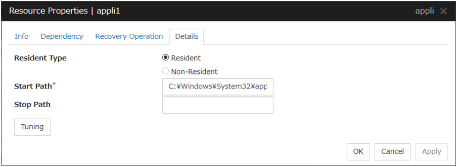
Resident Type
Specify the type of the application. Select one of the following:
Start Path (Within 1023 bytes)
Specify the name of the file that can be run when the application resource is started.
Stop Path (Within 1023 bytes)
Specify the name of the file that can be run when the application resource is stopped. The operation is as described below if the resident type is Resident.
Note
For the Start Path and Stop Path, specify an absolute path to the executable file or the name of the executable file of which the path configured with environment variable is effective. Do not specify a relative path. If it is specified, starting up the application resource may fail.
Tuning
Use this button to display the Application Resource Tuning Properties dialog box. Configure the detailed settings for the application resources.
Application Resource Tuning Properties
Parameter tab
Detailed parameter settings are displayed on this tab.
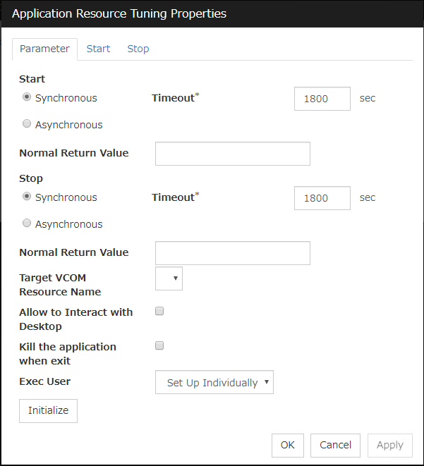
Synchronous (Start)
This setting is not available for a resident application.If the application is non-resident, select this to wait for the application to stop when it is run.
Asynchronous (Start)
This setting is not available for a resident application.If the application is non-resident, select this so as not to wait for the application to stop when it is run.
Normal Return Value (Start) (Within 1023 bytes)
This entry field cannot be entered when Asynchronous is selected.Specify what error code returned from the executable file set by Start Path is normal when ResidentType is Non-resident.
Note
In case that a batch file is specified as the executable file, an error cannot be detected when 1 is specified as Normal Return Value because 1 is returned when an error occurs with cmd.exe which executes the batch file.
Synchronous (Stop)
If the application is resident, and the stop path is not specified, select this to wait for the currently running application to stop. If the application is resident, and the stop path is specified, select this to wait for the application specified for the stop path to stop.If the application is non-resident, select this to wait for the application to stop when it is run.
Asynchronous (Stop)
If the application is resident, and the stop path is not specified, select this to wait for the currently running application to stop. If the application is resident, and the stop path is specified, select this to wait for the application specified for the stop path to stop.If the application is non-resident, select this so as not to wait for the application to stop when it is run.
Normal Return Value (Stop) (Within 1023 bytes)
This entry field cannot be entered when Asynchronous is selected.Specify what error code returned from the executable file set by Stop Path is normal when Resident Type is Non-resident.
Note
In case that a batch file is specified as the executable file, an error cannot be detected when 1 is specified as Normal Return Value because 1 is returned when an error occurs with cmd.exe which executes the batch file.
Timeout (Start) (1 to 9999)
This setting is not available for a resident application.Configure the timeout value to wait (synchronous) for a non-resident application to stop when the application is run. A value can be entered only when Synchronous is selected. If the application does not stop within the timeout value set here, it is considered as an error.
Timeout (Stop) (1 to 9999)
For a resident application, configure the timeout value to wait (Synchronous) for the currently running application or the application specified for the stop path to stop.The timeout value can be set only when Synchronous is selected. If the application does not stop within the timeout value set here, it is considered as an error.
Target VCOM Resource Name
Select a virtual computer name used as a computer name for the application resource. Virtual computer names and resource names that exist in the failover group where the application resource belong to are listed.When you specify this parameter, add the following environment variables and then start the application:COMPUTERNAME=<virtual computer name>_CLUSTER_NETWORK_FQDN_=<virtual computer name>_CLUSTER_NETWORK_HOSTNAME_=<virtual computer name>_CLUSTER_NETWORK_NAME_=<virtual computer name>
Allow to Interact with Desktop
Specify whether to allow the application to be run to interact with desktop. If this is selected, the application screen is displayed on the desktop when the application starts running.
Kill the application when exit
Specify whether or not to forcibly terminate the application as termination of deactivation. If this is selected, the application is forcibly terminated instead of normal termination. This is effective only when Resident Type is set to Resident and the stop path is not specified.
Exec User
Select a user by whom the application is to be executed, from users registered in the Account tab of Cluster Properties.With Set Up Individually specified, the settings of the user in the Start and Stop tabs are applied.With any value other than Set Up Individually specified, the settings in the Start and Stop tabs are not used: Those of the user specified for this parameter are applied.
Initialize
Click Initialize to reset the values of all items to their default values.
Start and Stop tabs
A detailed setting for starting and stopping the application is displayed.
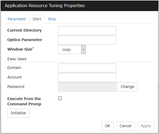
Current Directory (Within 1023 bytes)
Specify a directory for running the application.
Option Parameter (Within 1023 bytes)
Enter parameters to be entered for the application. If there are multiple parameters, delimit parameters with spaces. For a parameter that includes a space, enclose the parameter with double quotation marks.
Example: "param 1" param2
Window Size
Select the size of the window for running the application from the following:
Exec User Domain (Within 255 bytes)
Specify the domain of a user account that runs the application.
In the case of Stop tab, it is unnecessary to stop and/or resume the group.
Exec User Account (Within 255 bytes)
Specify the user account that runs the application. 1
In the case of Stop tab, it is unnecessary to stop and/or resume the group.
Exec User Password (Within 255 bytes)
Specify the password for the user account that runs the application.
In the case of Stop tab, it is unnecessary to stop and/or resume the group.
Execute from the Command Prompt
Specify whether to run the application from the command prompt (cmd.exe). Specify this when running an application (such as JavaScript and VBScript) whose extension is other than exe, cmd, or bat.
Initialize
Click Initialize to reset the values of all items to their default values.
- 1
When Exec User Account is left blank, the application is run by the local system account.
3.7. Understanding floating IP resources
3.7.1. Dependencies of floating IP resources
By default, this function does not depend on any group resource type.
3.7.2. Floating IP
Client applications can use floating IP addresses to access cluster servers. By using floating IP addresses, clients do not need to be aware of switching access destination server when a failover occurs or moving a group migration.
Floating IP addresses can be used on the same LAN and over the remote LAN.
Clients access Server 1 at its floating IP (FIP) address.
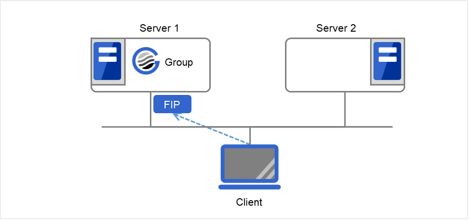
Fig. 3.43 Access to the floating IP address (1)
Even if a failover occurs from Server 1 to Server 2, clients access the FIP address without being aware of the actual, changed destination.
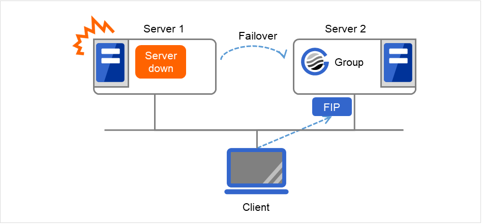
Fig. 3.44 Access to the floating IP address (2)
Address assignment
An IP address to assign for floating IP address needs to meet the condition described below:
Available host address which is in the same network address as the LAN that the cluster server belongs
Allocate as many IP addresses that meet the above condition as required (generally as many as failover groups). These IP addresses are the same as general host addresses, therefore, you can assign global IP addresses such as Internet.
You can also allocate IPv6addresses to floating IP addresses.
Routing
You do not need to make settings for the routing table.
Conditions to use
Floating IP addresses are accessible to the following machines:
Cluster server itself
Other servers in the same cluster and the servers in other clusters
Clients on the same LAN as the cluster server and clients on remote LANs
If the following conditions are satisfied, machines other than the above can also access floating IP addresses. However, connection is not guaranteed for all models or architectures of machines. Test the connection thoroughly by yourself before using those machines.
TCP/IP is used for the communication protocol.
ARP protocol is supported.
Even over LANs configured with switching hubs, floating IP address mechanism works properly. When a server goes down, the TCP/IP connection the server is accessing will be disconnected.
3.7.3. Notes on floating IP resources
If the FIP is activated forcibly when there is an IP address overlap, the NIC is invalidated due to the Windows OS specifications. Therefore, do not use Forced FIP Activation.
Notes on allocating floating IP addresses to IPv4 addresses
Notes on allocating floating IP addresses to IPv6 addresses
When a floating IP resource is set for a physical host, Windows registers the physical host name and FIP record in the DNS (if the property of the corresponding network adapter for registering addresses to the DNS is set to ON). To convert the IP address linked by the physical host name resolution into a physical IP address, set the relevant data as follows.
Check the setting of the network adapter to which the corresponding floating IP address is assigned, by choosing Properties - Internet Protocol Version 4 - Advanced - DNS tab - Register this connection's address in DNS. If this check box is selected, clear it.
Additionally, execute one of the following in order to apply this setting:
Reboot the DNS Client service.
Explicitly run the ipconfig/registerdns command.
Register the physical IP address of the network adapter to which the corresponding floating IP address is assigned to the DNS server statically.
When a floating IP resource adds a floating IP address to NIC by using a Windows OS API, the skipassource flag is not set and therefore does not take effect after activating a floating IP resource. Use applications such as PowerShell to set the skipassource flag after activating a floating IP resource.
For the usage of the Network Load Balancing (NLB) function of OS in the servers of the cluster, see " Coexistence with the Network Load Balancing function of the OS " in " Notes when creating the cluster configuration data" in " Notes and Restrictions" in the " Getting Started Guide".
3.7.4. Details tab
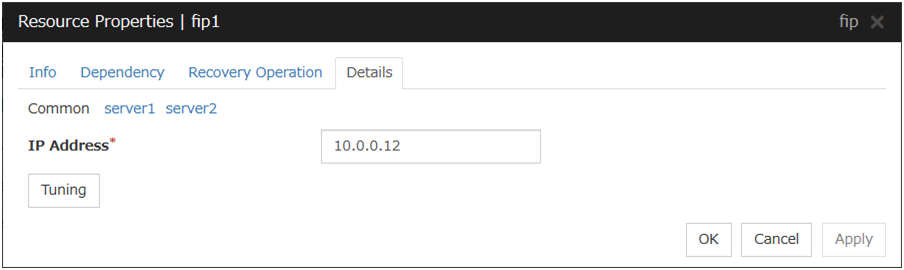
IP Address
Enter the floating IP address to be used.
If you specify an IPv4 address, the number of mask bits as 24 by default, find the address of the subnet mask on the local computer to match, you can add the floating IP address to the appropriate index.
Follow the instruction below to enter an IPv6 address.
Example: fe80::1
With the default value of prefix length 64 bit, floating IP resource searches for the addresses that have matching prefix on the local computer and adds floating IP address to the matching index. When there is more than one matching address, address is added to the index that has the largest index value.
In order to specify the prefix length explicitly, specify the prefix length after the address.
Example: fe80::1/8
In order to specify the index explicitly, specify %index after the address.
Example: fe80::1%5
The example above shows how to add a floating IP address to the index5.
Tuning
Opens the Floating IP Resource Tuning Properties dialog box where you can make detailed settings for the floating IP resource.
Floating IP Resource Tuning Properties
Detailed settings on floating IP resource are displayed.

Run ping
Specify this to verify if there is any overlapped IP address before activating floating IP resource by using the ping command.
ping
These are the detailed settings of the ping command used to check if there is any overlapped IP address before activating floating IP resource.
Judge NIC Link Down as Failure
Specify whether to check for an NIC Link Down before the floating IP resource is activated.
Initialize
Click Initialize to reset the values of all items to the default values.
3.8. Understanding mirror disk resources
3.8.1. Dependencies of mirror disk resources
By default, this function does not depend on any group resource type.
3.8.2. Mirror disk
Mirror disks are a pair of disks that mirror disk data between two servers in a cluster.
Mirroring is performed by partition. It requires the RAW partition (cluster partition) to record the management data as well as the data partition that is to be mirrored. In addition, the license of EXPRESSCLUSTER X Replicator 4.3 for Windows is necessary on both servers that mirroring is performed.
Example:
Combination
Server 1
Server 2
Correct
SCSI
SCSI
Correct
IDE
IDE
Incorrect
IDE
SCSI
Combination
Head
Sector
Cylinder
Correct and Server 1
240
63
15881
Correct and Server 2
240
63
15881
Incorrect and Server 1
240
63
15881
Incorrect and Server 2
120
63
31762
If it is not possible to make both servers have exactly the same disk type and geometry, check the size of data partitions in precise by using the clpvolsz command. If the disk size does not match, shrink the larger partition by using the clpvolsz command again.
For details on the clpvolsz command, see "Tuning partition size (clpvolsz command)" in "8. EXPRESSCLUSTER command reference" in this guide.
Example: Adding a SCSI disk to each server to create a pair of mirroring disks.
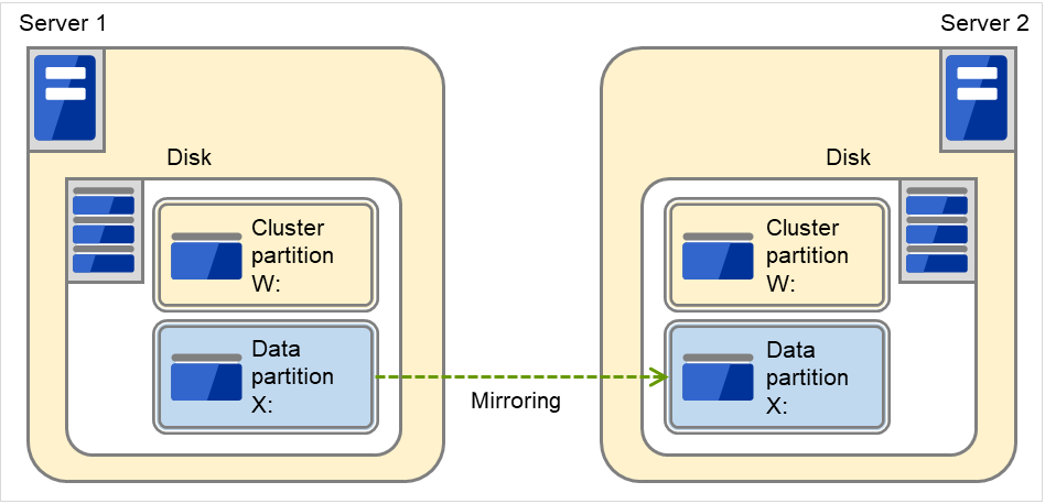
Fig. 3.45 Adding disks for a pair of mirror disks
Example: Using available area of the IDE disk on which OS of each server are stored to create a pair of mirroring disks.
The following figure illustrates using the free space of each disk as a mirror partition device (cluster partition and data partition):
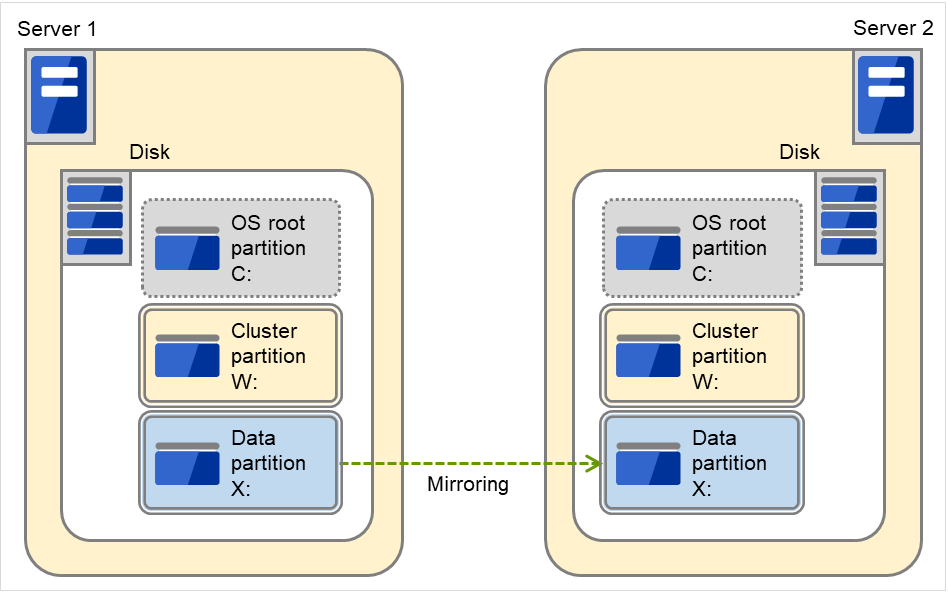
Fig. 3.46 Using the free space of each disk for a mirror partition
A mirror partition (cluster partition, data partition) can be allocated on the same disk as OS.
Example: Adding one SCSI disk to each server to create two pairs of mirroring disks.
The following figure illustrates each disk on which a pair of a cluster partition and a data partition is created:
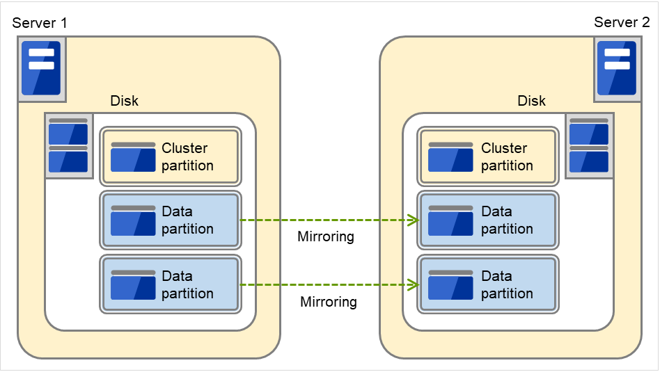
Fig. 3.47 Using multiple areas of each disk for mirror partitions
Allocate a cluster partition and two data partitions in a pair on a single disk.
Assign 0 and 1 for the offset index of the cluster partition management area to be used in each data partition.
Example: Adding two SCSI disks for each server to create two mirroring partitions.
The following figure illustrates using mirror partitions prepared from two pairs of disks on which partitions of the same size are created:
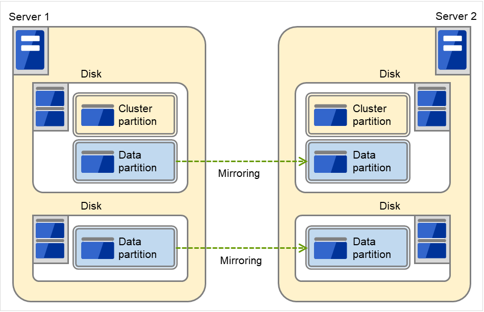
Fig. 3.48 Using two pairs of disks as mirror partitions
Secure a cluster partition and data partition on the first disk and a data partition on the second disk.
Routing and Remote Access Assign 0 and 1 for the offset index of the cluster partition management area to be used in each data partition.
A cluster partition can be secured on each disk. In that case, the offset index is assigned to be 0 and 0.
When performing mirroring in the asynchronous mode, an access to a cluster partition is generated in accordance with writing in a data partition. The access to a disk can be distributed by securing a cluster partition and data partition on separate disks.
Example: Adding one SCSI disk for three servers to create two mirroring partitions.
The following figure illustrates using data partitions between Server 1 and Server 2 and between Server 2 and Server 3, by preparing each disk for each combination of a cluster partition and two partitions of the same size:
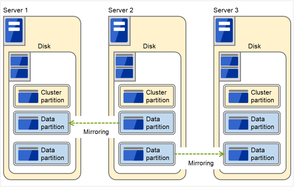
Fig. 3.49 Using multiple areas of each disk for mirror partitions (with three servers)
Allocate a cluster partition and two data partitions on each server.
On Server 2, the following two data partitions are required: One is used for mirroring with Server 1 while the other is used for mirroring with Server 3.
Assign 0 and 1 as the offset index of the cluster partition management area to be used in each data partition.
Data partition
Partitions where data that is mirrored by EXPRESSCLUSTER (such as application data) is stored are referred to as data partitions.Allocate data partitions as follows:
Allocate the partition on a basic disk. The dynamic disk is not supported.
When making data partitions as logistical partitions on the extended partition, make sure the data partitions are logical partition on both servers. The actual size may be different even the same size is specified on both basic partition and logical partition
The access to the data partition is controlled by EXPRESSCLUSTER.
Cluster partition
Dedicated partitions used in EXPRESSCLUSTER for mirror partition controlling are referred to as cluster partition.Allocate cluster partitions as follows:
Access control of a data partition
The data partition to be mirrored by a mirror disk resource can be accessed only from the active server where a mirror disk resource is activated.
EXPRESSCLUSTER is responsible for the access control of the file system. Application's accessibility to a data partition is the same as switching partition (disk resources) that uses shared disks.
Mirror partition switching is done for each failover group according to the failover policy.
By storing data required for applications on data partitions, the data can be automatically used after failing over or moving failover group.
The following figure illustrates mirroring disk data by a pair of Mirror disk 1 with Server 1 and Mirror disk 2 with Server 2:
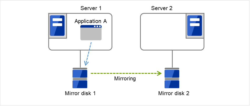
Fig. 3.50 Mirror disk configuration (1)
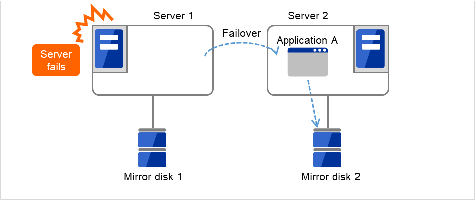
Fig. 3.51 Mirror disk configuration (2)
3.8.3. Understanding mirror parameters
The maximum size of request queues
The improvement in the performance is expected when you set a larger value under the following conditions:
Large amount of physical memory is installed on the server and there is plenty of available memory.
The performance of the disk I/O is high.
It is recommended to select a smaller value under the conditions:
Small amount of physical memory is installed on the server.
I/O performance of the disk is low.
Mirror Connect Timeout
This is the time required to cut a mirror connect when there is no response on the communication among servers and/or when the data synchronization has not completed at the time of mirror recovery and/or data synchronization. The time for timeout needs to be configured longer, if the line speed of the mirror connect is slow and/or the load to the mirror disk is high.
Adjust this parameter below the timeout value of heartbeat, based on the following calculation.
Heartbeat timeout = Mirror connect timeout + 10 seconds
* For the settings of the heartbeat timeout, see "Timeout tab" in "Cluster properties" in "2. Parameter details" in this guide.
Initial Mirror Construction
Specify if initial mirroring is configured when activating cluster for the first time after the cluster is created.
Mode
Switch the synchronization mode of mirroring.
Mode |
Overview |
Explanation |
|---|---|---|
Synchronous |
Complete match of the data in the active and standby servers is guaranteed. |
Writing the data to the mirrored disk is finished when writing the data to both local and remote disks is finished. |
Asynchronous |
The order to write in the updated data is guaranteed. However, the latest updated data may be lost, if a failover is performed in the state that a mirror disk resource cannot be deactivated as servers are down.
The data is transferred to the remote disk after writing request is queued and performed on the background.
|
Writing the data to the mirrored disk is finished when writing the data to the local disk is finished.
After queuing is kept in the kernel space memory, it is transferred to the user space memory. When the volume of data reaches a limit that the user space memory can keep, the data is sent out to a temporary file and kept there.
|
Kernel Queue Size
Specify the size of the request for writing to the remote disk to be kept in the kernel space memory when the mode is set to Asynchronous. Normally, default value is specified.
Input and output are completed, if writing data can be saved in the kernel queue.
If taking data into the application queue is delayed as the load on CPU is high, the size is set larger. However, if the size is too large, it will result in compressing the system resource.
Application Queue Size
Specify the size of the request for writing to the remote disk to be kept in the user space memory when the mode is set to Asynchronous. Normally, the default value is used. However, if a high-speed network is used, the frequency of creating a temporary file can be reduced and the overhead caused by input and output can be decreased by making the queue size larger.
Upper Bound of Communication Band
When the mode is Asynchronous, the server tries to transfer data that has been queued to the standby server. When the channel for mirror connection is used for connections for other applications, the communication band may become busy. In this case, by setting the bound of communication band for the mirror connect communication, the impact on other communications can be reduced. If the communication band for mirror connect is smaller than the average amount of data to be written into the mirror disk, the queued data cannot be fully transferred to the standby server, which can result in overflow and suspension of mirroring. The bandwidth should be large enough for data to be written into the business application.
This function makes a limit to the communication band by having a maximum of one-second pause when the total amount of data to be transferred per second exceeds the configured value. If the size of data to be written into the disk at a time is greater than the configured value, expected performance may not be achieved. For example, even if you set the value of communication band limit to be 64Kbyte or smaller, the actual amount of communication during copy can be greater than the configured value because the size of data to be transferred for a copy of a mirror disk at a time is 64 Kbyte.
See also
In addition to the limit on the communication band for each mirror disk resource, you can also set a limit on the communication band for each mirror disk connect by using a standard Windows function. For details, see "Limit on the band for mirror connect communication" in "The system maintenance information" in the "Maintenance Guide".
History Files Store Folder
Specify the folder that keeps the temporary file which is created when the request for writing to the remote disk in the Asynchronous mode cannot be recorded in the application queue. When the communication band runs short, data is recorded up to the limit of the disk space if the limit of the history file size is not specified. Thus, specifying a folder on the system disk runs out of the empty space and the system behavior may become unstable. Therefore, if you want to suspend mirroring when recording data is exceeded a certain size, create a dedicated partition or specify the limit of the history file size.
Do not specify any folder on the cluster partition and data partition to the history files store folder. Also, do not specify a folder containing a 2-byte character in the path.
Thread Timeout
This is the time that timeout is occurred when data cannot be transferred to the application queue from the kernel queue in the mode of Asynchronous. When it is timed out, a mirror connect is cut.
Timeout may occur, if the data transfer to the application queue is delayed due to high load. In this case, increase the timeout value.
Encrypt mirror communication
3.8.4. Examples of mirror disk construction
Execute the initial mirror construction
First, create application data to be duplicated (if available before the cluster construction) in the data partition (e.g. initial database) of Mirror disk 1 on the active server in advance. For information on the partition configuration, refer to "3.8.2. Mirror disk". Next, install EXPRESSCLUSTER on each of Server 1 and Server 2.
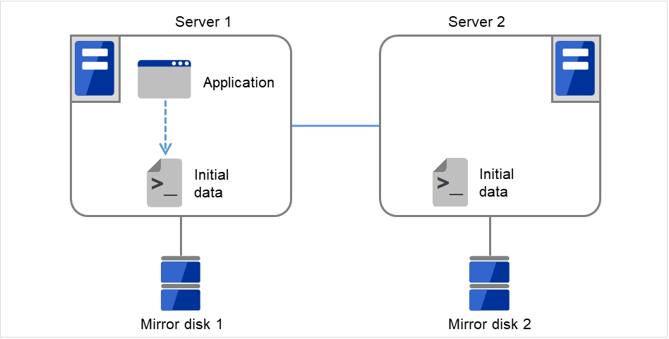
Fig. 3.52 Example of mirror disk construction: executing initial mirror construction (1)
Then start the initial mirror construction. Completely copy the content of Mirror disk 1 on Server 1 to Mirror disk 2 on Server 2.
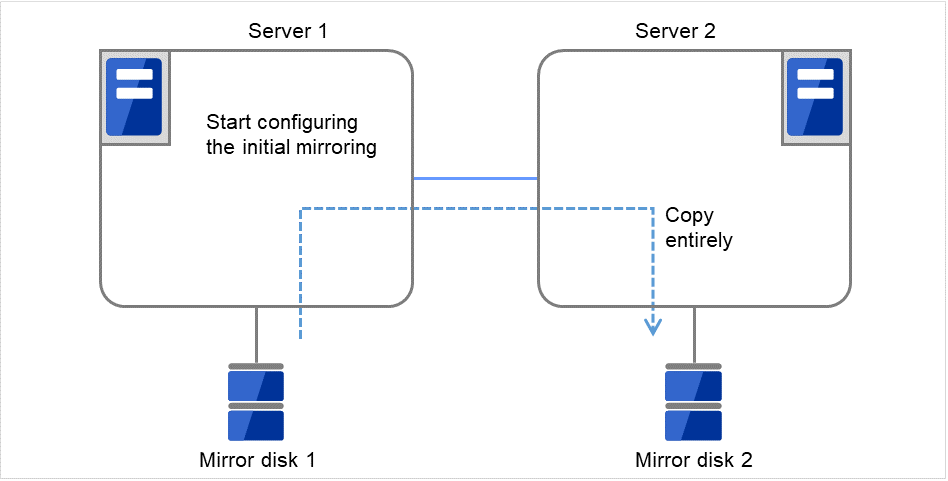
Fig. 3.53 Example of mirror disk construction: executing initial mirror construction (2)
Do not execute the initial mirror construction
Follow the procedures below to have identical data in the data partition on both servers:
If application data to be duplicated can be prepared before configuring a cluster, create it on data partition of the mirror disk on the active server in advance (ex. initial data of the database).
Install EXPRESSCLUSTER and configure a cluster without executing the initial mirror construction.
Shut down the cluster.
Remove disks that have data partitions on both servers, and connect to the Linux server. Then copy the data in the data partition on the active server to the data partition on the standby server by using the dd command in the state that disks are not mounted.
Return disks to the active and standby server and start both servers.
3.8.5. Notes on mirror disk resources
Set both servers so that the identical partitions can be accessed under the identical drive letter.
If a drive letter different from those used on partition is set, the drive letter will be changed when the mirror disk resource is started. If the drive letter is used on any other partitions, starting up the mirror disk resource will fail.
To change the configuration so that the disk mirrored using a hybrid disk resource will be mirrored using a mirror disk resource, first delete the existing hybrid disk resource from the configuration data, and then upload the data. Next, add a mirror disk resource to the configuration data, and then upload it again.
For the data partition and the cluster partition of hybrid disk resources, use disk devices with the same logical sector size on all servers. If you use devices with different logical sector sizes, they do not operate normally. They can operate even if they have different sizes for the data partition and the cluster partition.
Examples)
Logical sector size of the partition
Description
Server 1
Server 1
Server 2
Server 2
Data partition
Cluster partition
Data partition
Cluster partition
OK
512B
512B
512B
512B
The logical sector sizes are uniform.
OK
4KB
512B
4KB
512B
The data partitions have a uniform size of 4 KB, and the cluster partitions have a uniform size of 512 bytes.
NG
4KB
512B
512B
512B
The logical sector sizes for the data partitions are not uniform.
NG
4KB
4KB
4KB
512B
The logical sector sizes for the cluster partitions are not uniform.
3.8.6. Details tab
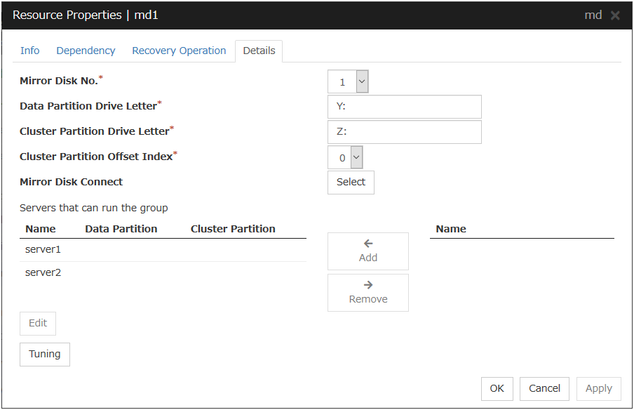
Mirror Disk No.
Select the number to be allocated to the mirror partition.
Data Partition Drive Letter (Within 1023 bytes)
Specify the drive letter (A to Z) of the data partition.
Cluster Partition Drive Letter (Within 1023 bytes)
Specify the drive letter (A to Z) to the cluster partition.
Cluster Partition Offset Index
Select an index number for the area used in the cluster partition. When using the multiple mirror disks, assign different numbers for each mirror disk so that the areas to be used in the cluster partition are not overlapped.
Select
Select the communication path for the data mirroring communication (mirror disk connect). Click Select to display the Selection of Mirror Disk Connect dialog box.
For mirror disk connect settings, see "Interconnect tab" in "Cluster properties" in "2. Parameter details" in this guide.
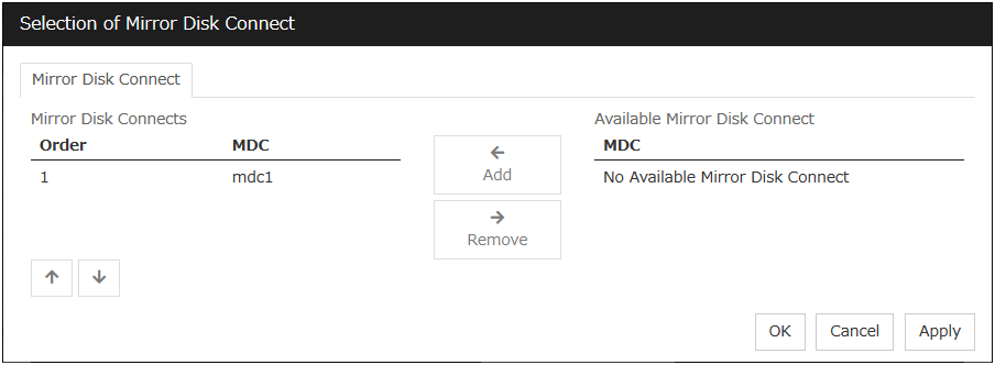
Add
Click this button to add the selected server to Servers that can run the group. When this button is clicked, the dialog box that allows for selection of a partition of the selected server is displayed.
Important
Specify different partitions for data partition and cluster partition. If the same partition is specified, data on the mirror disk may be corrupted. Make sure not to specify the partition on the shared disk for the data partition and cluster partition.
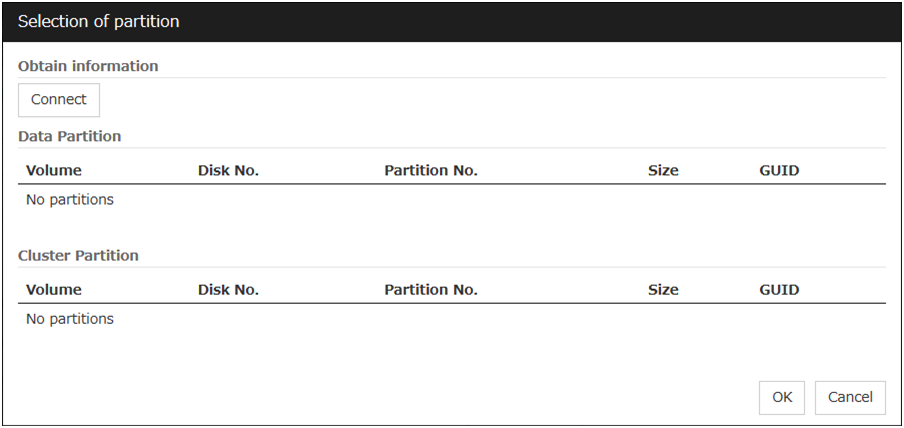
Remove
Use this button to delete a server from Servers that can run the group.
Edit
Use this button to display the dialog box to select the partition of the selected server.
Tuning
Opens the Mirror Disk Resource Tuning Properties dialog box. You make detailed settings for the mirror disk resource there.
Mirror DiskResource Tuning Properties
Mirror tab
The advanced settings of mirror are displayed.
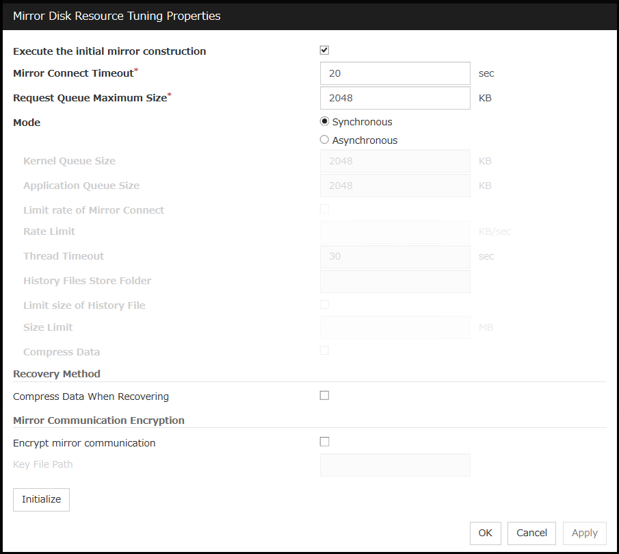
Execute the initial mirror construction
Specify whether to execute an initial mirror construction (full copy of data partition) when configuring a cluster.
Mirror Connect Timeout (2 to 9999)
Specify the timeout for mirror connect.
Request Queue Maximum Size (512 to 65535)
Specify the size of queue that a mirror disk driver uses to queue I/O requests on the communication among servers.
Mode
Switch the mode of the mirror data synchronization.
Kernel Queue Size (512 to 65535)
Specify the queue size of the kernel space to save the I/O data of the asynchronous mirror temporarily.
Application Queue Size (512 to 65535)
Specify the queue size of the user space to save the I/O data of the asynchronous mirror temporarily.
Rate limitation of Mirror Connect (0 to 999999999)
Set the upper limit of the communication band used by the mirror connect.
Thread Timeout (2 to 9999)
Specify the timeout when it becomes unable to transfer from the kernel queue to the application queue.
History Files Store Folder (Within 1023 bytes)
Specify the destination folder to store the file when I/O data is overflowed form the application queue. It is required to specify a folder that has sufficient free space so that the remote disk and the asynchronous I/O data can be kept as a file.
Do not specify any folder in the cluster partition and data partition to the history files store folder. Additionally do not specify a folder that contains two byte characters in the path.
Also, it is recommended to set a history files store folder, in addition to the system drive of Windows (Normally, the C: drive is used.). If it is set on the system drive, due to I/O running concurrently, a failure may occur. For example, the mirror processing is delayed or the system behavior may become unstable.
Size limitation of History File (0 to 999999999)
Set the size limit of temporary files stored in the history file store folder. If the upper limit of size is specified, mirroring will stop when the total amount of this temporary file reaches the limit. The configured value is only applied to the limit of the temporary file size for the mirror disk resources, and this value does not set the limit of the amount of the temporary files in the history file store folder.
Compress data
Specify whether to compress the mirror data flowing through the mirror disk connect.
Compress Data When Recovering
Specify whether to compress the mirror data flowing through the mirror disk connect for the purpose of mirror recovery.
Mirror Communication Encryption
Choose whether to encrypt data passing through mirror disk connects. This setting affects both data for mirror synchronization and data for mirror recovery.
Key File Path
Specify a key file to encrypt data passing through mirror disk connects.
Note
The key file to be used is generated by using the clpkeygen command. For more information on the clpkeygen command, refer to "8. EXPRESSCLUSTER command reference" - "Creating a key file for encrypting communication data (clpkeygen command)".
Important
Be sure to use the same key file on all servers which can activate mirror disk resources. Using different key files leads to unsuccessful mirroring.
Initialize
Click Initialize to reset the values of all items to their default values.
3.8.7. Notes on operating mirror disk resources
If mirror data was synchronized on both servers when the cluster was shut down, use one of the two orders noted below to start the servers.
Start both servers simultaneously
Start the first server, and then start the second server after the first server has started
Do not consecutively start and shutdown both servers 2. The servers communicate with each other to determine whether the mirror data stored on each server is up to date. Consecutively starting and shutting down both servers prevents the servers from properly determining whether mirror data is up to date and mirror disk resources will fail to start the next time both servers are started.
- 2
In other words, do not start and shut down the first server, and then start and shut down the second server.
3.9. Understanding registry synchronization resources
3.9.1. Dependencies of registry synchronization resources
By default, this function depends on the following group resource types.
Group resource type |
|---|
Floating IP resource |
Virtual IP resource |
Virtual computer name resource |
Disk resource |
Mirror disk resource |
Hybrid disk resource |
Print spooler resource |
CIFS resource |
NAS resource |
AWS elastic ip resource |
AWS virtual ip resource |
AWS DNS resource |
Azure probe port resource |
Azure DNS resource |
3.9.2. Registry synchronization resources

Fig. 3.54 Registry synchronization resource (1)
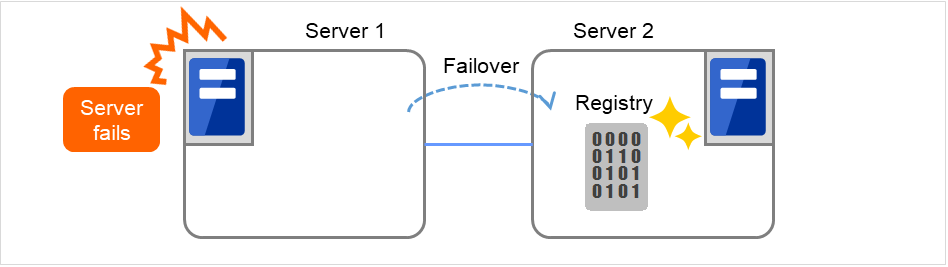
Fig. 3.55 Registry synchronization resource (2)
Registry keys to be synchronized at failover can be configured. When the content in a registry key set as synchronization target is updated while registry synchronization resource is active, the updated content is applied to the registry of the Failover Target Server.
The following describes how a registry synchronization resource synchronizes registry:
When there is a registry synchronization resource in a failover group, update of a registry key that has been configured is monitored when the registry synchronization resource is activated.
When the registry key update is detected, what is in the registry key is saved as a file in the local disk. Then the file is delivered to each Failover Target Server.
The servers that received the file keep it in their local disks. If a failover occurs and registry synchronization resource is activated in a server that received the file, the content of the file is restored in the corresponding registry key.
3.9.3. Notes on registry synchronization resources
Do not open synchronization target registry keys in the standby server.
If a synchronization target registry key is opened when a failover occurs, restoration of the registry will fail. To start and stop applications that use the synchronization target registry key, use a script resource within a control of EXPRESSCLUSTER.
Minimize the number of synchronization target registry keys. Do not set more than needed. It is not recommended to set a registry key that is frequently updated as a synchronization target registry key.
Saving in a file and delivering the file to other servers is done every time a synchronization target registry key is updated. The number of synchronization target registry keys and frequency of updating them can affect the system performance. Do not change or update a synchronization target registry key.
For the synchronization target registry keys, the following can be set. The registry keys other than those listed below cannot be synchronized.
- Any key under the HKEY_USERS
- Any key under the HKEY_LOCAL_MACHINE
Do not set the following keys.
Keys under the HKEY_LOCAL_MACHINE/SOFTWARE/NEC/EXPRESSCLUSTER
HKEY_LOCAL_MACHINE/SOFTWARE/NEC
HKEY_LOCAL_MACHINE/SOFTWARE
HKEY_LOCAL_MACHINE
Do not set the keys that are in parent-child relationship within the same resource.
Up to 16 synchronization target registry keys can be set per resource.
The following restrictions apply to names of the synchronization target registry keys:
The characters that can be used for registry key are determined by the OS specifications.
Up to 259 bytes can be used. Do not set the key name of 260 or larger bytes.
3.9.4. Details tab
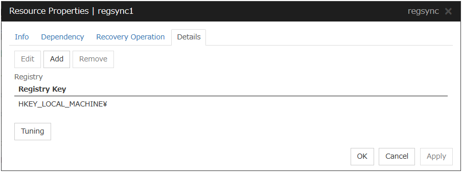
Add
Use this button to add a registry key to monitor. The Enter registry key dialog box is displayed.

Registry Key
Enter a registry key to synchronize and click OK.
Remove
Click this button to delete a registry key from synchronization target listed in Registry List.
Edit
The Enter registry key dialog box is displayed. The selected registry keys are listed in Registry List. Edit a registry key and click OK.
Registry Synchronization Resource Tuning Properties
Parameter tab
The detailed setting for registry synchronization resource is displayed.
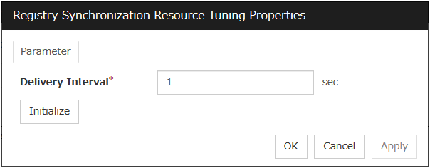
Delivery Interval (1 to 99)
Specify the interval to deliver the updated registry key information to other servers.
When short-time interval is set
Updated information is immediately delivered to other servers.
The system may get heavily loaded by frequently updating a registry key.
When long-time interval is set
A delay in delivering updated information to other servers may occur. If a failover occurs before delivery of the updated information is not completed, it will not be delivered to the Failover Target Server.
Increase in system load due to synchronization can be reduced when a registry key is frequently updated.
Initialize
Click Initialize to reset the values of all items to their default values.
3.10. Understanding script resources
You can register scripts managed by EXPRESSCLUSTER and run when starting, stopping, failing over, or moving a group in EXPRESSCLUSTER. It is also possible to register your own scripts for script resources.
Note
The same version of the application to be run from script resources must be installed on all servers in failover policy.
3.10.1. Dependencies of script resources
By default, this function depends on the following group resource types.
Group resource type |
|---|
Floating IP resource |
Virtual IP resource |
Virtual computer name resource |
Disk resource |
Mirror disk resource |
Hybrid disk resource |
Print spooler resource |
Registry synchronization resource |
CIFS resource |
NAS resource |
AWS elastic ip resource |
AWS virtual ip resource |
AWS DNS resource |
Azure probe port resource |
Azure DNS resource |
3.10.2. Scripts in script resources
Types of scripts
Start script and stop script are provided in script resources. EXPRESSCLUSTER runs a script for each script resource when the cluster needs to change its status. You have to write procedures in these scripts about how you want applications to be started, stopped, and restored in your cluster environment.
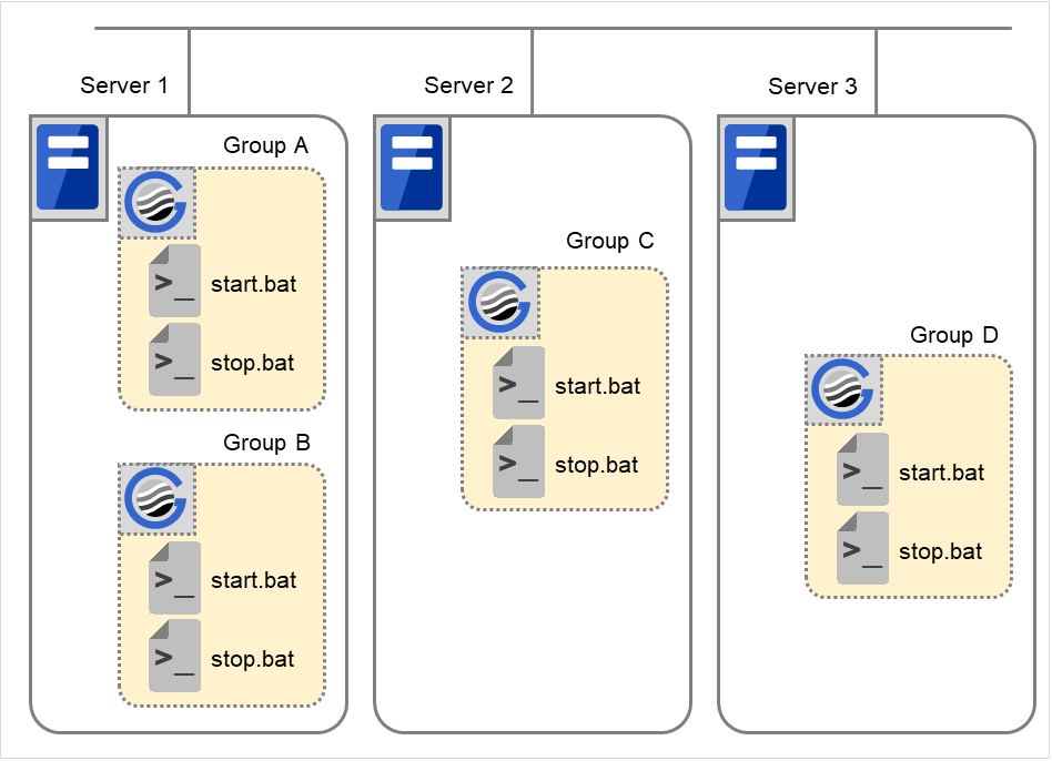
Fig. 3.56 Start script and stop script
- start.bat
Start script
- stop.bat
Stop script
3.10.3. Environment variables in script of script resource
Environment Variable |
Value of environment variable |
Meaning |
|---|---|---|
CLP_EVENT
...script starting factor
|
START |
The script was run:
- by starting a cluster;
- by starting a group;
- on the destination server by moving a group;
- on the same server by restarting a group due to the detection of a monitor resource error; or
- on the same server by restarting a group resource due to the detection of a monitor resource/ARMLOAD command error.
|
FAILOVER |
The script was run on the Failover Target Server:
- by the server's failing;
- due to the detection of a monitor resource/ARMLOAD command error; or
- because activation of group resources failed.
|
|
RECOVER |
- The server is recovered;
- due to detection of a monitor resource/ARMLOAD command error; or
- because activation of group resources failed.
|
|
CLP_FACTOR
...group stopping factor
|
CLUSTERSHUTDOWN |
The group was stopped by stopping the cluster. |
SERVERSHUTDOWN |
The group was stopped by stopping the server. |
|
GROUPSTOP |
The group was stopped by stopping the group. |
|
GROUPMOVE |
The group was moved by moving the group. |
|
GROUPFAILOVER |
The group failed over because an error was detected in monitor resource; or the group failed over because of activation failure in group resources. |
|
GROUPRESTART |
The group was restarted because an error was detected in monitor resource. |
|
RESOURCERESTART |
The group resource was restarted because an error was detected in monitor resource. |
|
CLP_LASTACTION
...process after cluster shutdown
|
REBOOT |
In case of rebooting OS |
HALT |
In case of halting OS |
|
NONE |
No action was taken. |
|
CLP_SERVER
...server where the script was run
|
HOME |
The script was run on the primary server of the group. |
OTHER |
The script was run on a server other than the primary server of the group. |
|
CLP_DISK 3
...partition connection information on shared or mirror disks
|
SUCCESS |
There was no partition with connection failure. |
FAILURE |
There was one or more partition with connection failure. |
|
CLP_PRIORITY
... the order in failover policy of the server where the script is run
|
1 to the number of servers in the cluster |
Represents the priority of the server where the script is run. This number starts from 1 (The smaller the number, the higher the server's priority).
If CLP_PRIORITY is 1, it means that the script is run on the primary server.
|
CLP_GROUPNAME
...Group name
|
Group name |
Represents the name of the group to which the script belongs. |
CLP_RESOURCENAME
...Resource name
|
Resource name |
Represents the name of the resource to which the script belongs. |
CLP_VERSION_FULL
...EXPRESSCLUSTER full version
|
EXPRESSCLUSTER full version |
Represents the EXPRESSCLUSTER full version.
(Example) 12.33
|
CLP_VERSION_MAJOR
...EXPRESSCLUSTER major version
|
EXPRESSCLUSTER major version |
Represents the EXPRESSCLUSTER major version.
(Example) 12
|
CLP_PATH
...EXPRESSCLUSTER installation path
|
EXPRESSCLUSTER installation path |
Represents the path where EXPRESSCLUSTER is installed.
(Example) C:\Program Files\EXPRESSCLUSTER
|
CLP_OSNAME
...Server OS name
|
Server OS name |
Represents the OS name of the server where the script was executed.
(Example) Windows Server 2012 Standard
|
CLP_OSVER
...Server OS version
|
Server OS version |
Represents the OS version of the server where the script was executed.
(Example) 6.2.0.0.274.3
|
CLP_SERVER_PREV
...Failover source server name
|
Server name |
Represents the failover source of the group which the script belongs to only when CLP_EVENT is FAILOVER. Indicates an indefinite value when CLP_EVENT is other than FAILOVER. |
Note
On Windows Server 2016 or later, CLP_OSVER is set the same information as on Windows Server 2012 R2.
- 3
It is available for disk resource, mirror disk resource and hybrid disk resource.
Environment variable |
Value of environment variable |
Meaning |
|---|---|---|
CLP_EVENT
...script starting factor
|
STANDBY |
The script was run on the standby server.
|
CLP_SERVER
...server where the script was run
|
HOME |
The script was run on the primary server of the group. |
OTHER |
The script was run on a server other than the primary server of the group. |
|
CLP_PRIORITY
... the order in failover
policy of the server
where the script is run
|
1 to the number of servers in the cluster |
Represents the priority of the server where the script is run. This number starts from 1 (The smaller the number, the higher the server's priority).
If CLP_PRIORITY is 1, it means that the script is run on the primary server.
|
CLP_GROUPNAME
...Group name
|
Group name |
Represents the name of the group to which the script belongs. |
CLP_RESOURCENAME
...Resource name
|
Resource name |
Represents the name of the resource to which the script belongs. |
CLP_VERSION_FULL
...Full version of EXPRESSCLUSTER
|
Full version of EXPRESSCLUSTER |
Represents the full version of EXPRESSCLUSTER (e.g. 12.33 ). |
CLP_VERSION_MAJOR
...Major version of EXPRESSCLUSTER
|
Major version of EXPRESSCLUSTER |
Represents the major version of EXPRESSCLUSTER (e.g. 12). |
CLP_PATH
...EXPRESSCLUSTER installation path
|
EXPRESSCLUSTER installation path |
Represents the EXPRESSCLUSTER installation path (e.g. C:\Program Files\EXPRESSCLUSTER). |
CLP_OSNAME
...Server OS name
|
Server OS name |
Represents the OS name of the server where the script was executed.
(E.g. Windows Server 2012 Standard)
|
CLP_OSVER
...Server OS version
|
Server OS version |
Represents the OS version of the server where the script was executed.
(E.g. 6.2.0.0.274.3)
|
3.10.4. Execution timing of script resource scripts
This section describes the relationships between the execution timings of start and stop scripts and environment variables according to cluster status transition diagram.
To simplify the explanations, a 2-server cluster configuration is used as an example. See the supplements for the relations between possible execution timings and environment variables in 3 or more server configurations.
Server
Server status
Normal (properly working as a cluster)
Stopped (cluster is stopped)
(Example) Group A is working on a normally running server.
Each group is started on the top priority server among active servers.
Three Group A, B and C are defined in the cluster, and they have their own failover policies as follows:
Group
First priority server
Second priority server
A
Server 1
Server 2
B
Server 2
Server 1
C
Server 1
Server 2
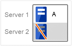
Cluster status transition diagram
This diagram illustrates a typical status transition of cluster.
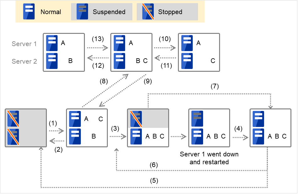
Fig. 3.57 Example of cluster status transition: overview
Numbers 1. to 13. in the diagram correspond to descriptions as follows.
1. Normal startup
Normal startup here refers to that the start script has been run properly on the primary server.
Each group is started on the server with the highest priority among the active servers.
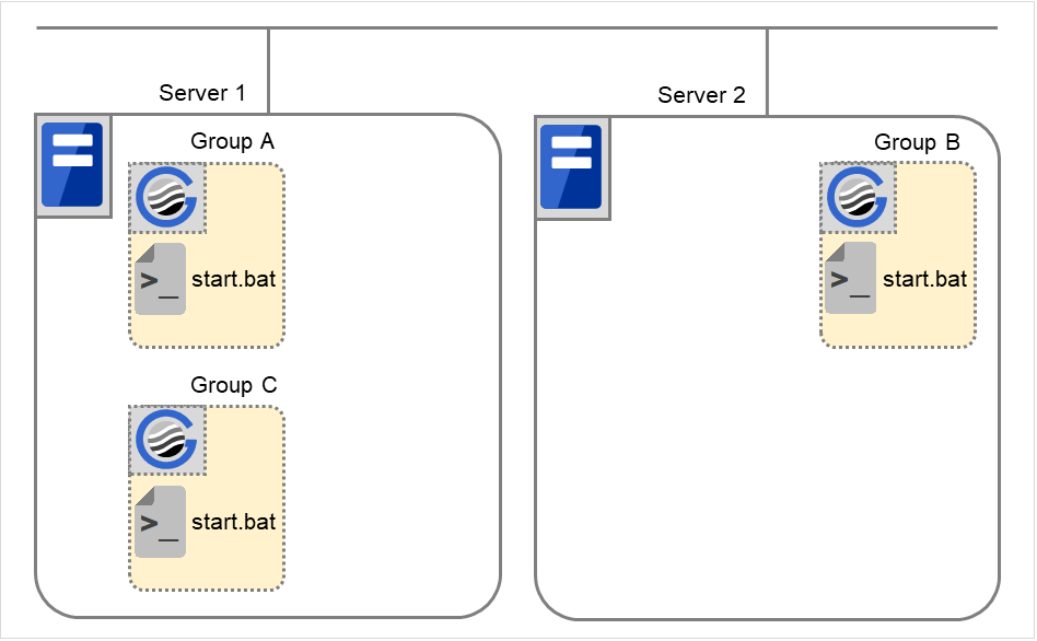
Fig. 3.58 Situation and script execution: normal startup
Environment variables for start.bat
Group A
Group B
Group C
CLP_EVENT
START
START
START
CLP_SERVER
HOME
HOME
HOME
2. Normal shutdown
Normal shutdown here refers to a cluster shutdown immediately after the start script corresponding to a stop script was run by performing normal startup or by moving a group (online failback).
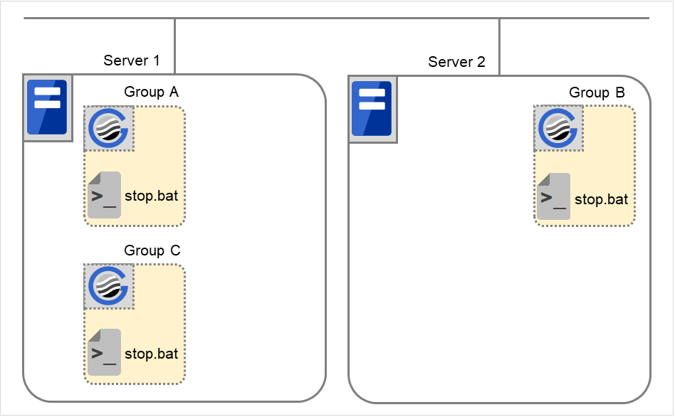
Fig. 3.59 Situation and script execution: normal shutdown
Environment variables for stop.bat
Group A
Group B
Group C
CLP_EVENT
START
START
START
CLP_SERVER
HOME
HOME
HOME
3. Failover at the failed Server 1
The start script of a group that has Server 1 as its primary server will be run on a lower priority server (Server 2) if an error occurs. You need to write CLP_EVENT(=FAILOVER) as a branching condition for triggering application startup and recovery processes (such as database rollback process) in the start script in advance.
For the process to be performed only on a server other than the primary server, specify CLP_SERVER(=OTHER) as a branching condition and describe the process in the script.
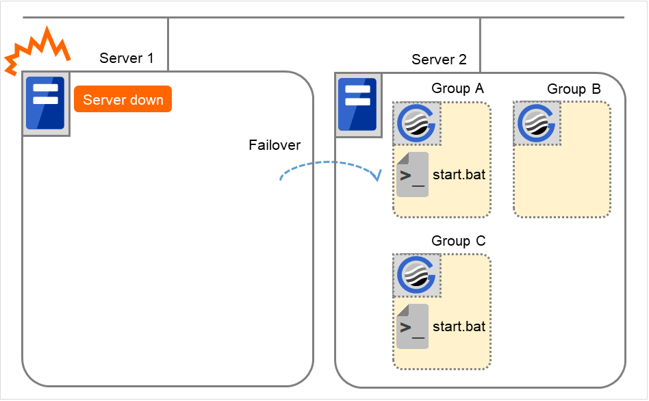
Fig. 3.60 Situation and script execution: failover due to server down
Group A
Group C
CLP_EVENT
FAILOVER
FAILOVER
CLP_SERVER
OTHER
OTHER
4. Recovering Server 1 to cluster
When Server 1 that has been rebooted (operating as non-cluster) returns to a cluster, the start script of the failover group that was running when a failover occurred is run in Server 1. This means recovery is executed in the server where the failover has occurred.
To execute a recovery (for example, recovering database information in a local disk), you need to write CLP_EVENT(=RECOVER) as a branching condition. Even if recovery is not required, you need to write the script not to start the operation.
For data mirroring operation, data is restored (reconfiguration of mirror set) at cluster recovery.
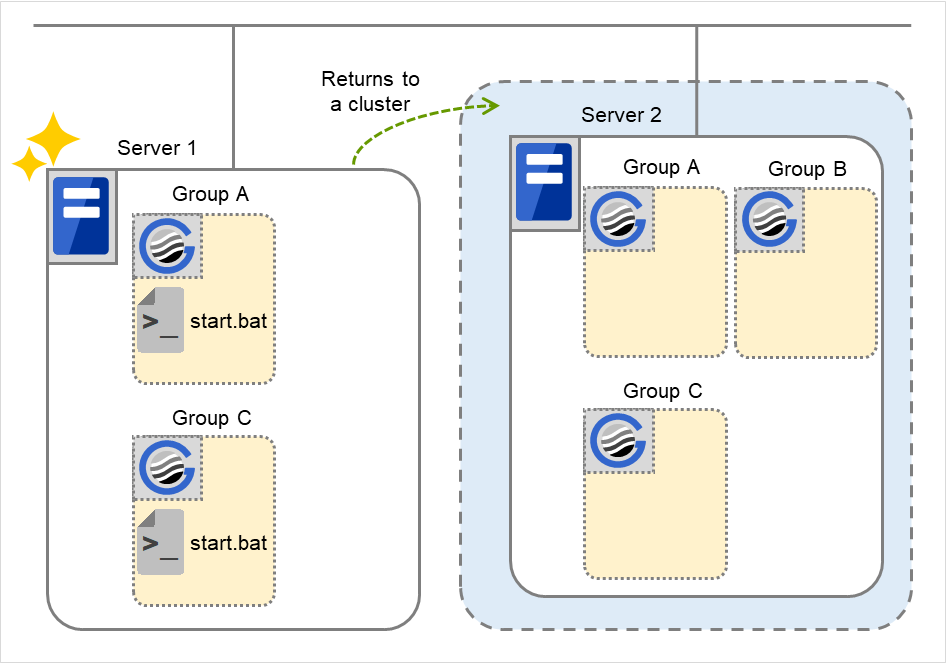
Fig. 3.61 Situation and script execution: returning a server to the cluster
Environment variables for start.bat
Group A
Group C
CLP_EVENT
RECOVER
RECOVER
CLP_SERVER
HOME
HOME
5. Cluster shutdown after failover of Server 1
The stop scripts of the Group A and C are run on Server 2 to which the groups failed over (the stop script of Group B is run by a normal shutdown).
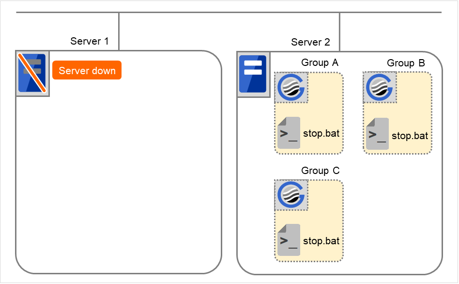
Fig. 3.62 Situation and script execution: cluster shutdown after failover
Environment variables for stop.bat
Group A
Group B
Group C
CLP_EVENT
FAILOVER
START
FAILOVER
CLP_SERVER
OTHER
HOME
OTHER
6. Moving of Group A and C
After the stop scripts of Group A and C are run on Server 2 to which the groups failed over, their start scripts are run on Server 1.
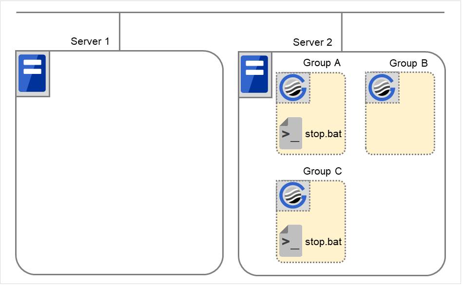
Fig. 3.63 Situation and script execution: moving Groups A and C (1)
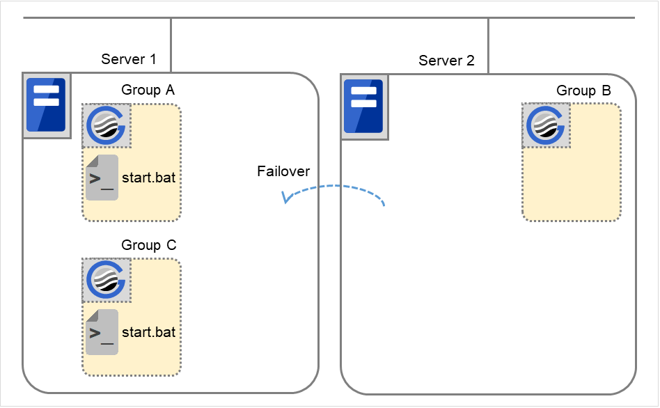
Fig. 3.64 Situation and script execution: moving Groups A and C (2)
Environment variables for stop.bat
Group A
Group C
CLP_EVENT
FAILOVER 4
FAILOVER
CLP_SERVER
OTHER
OTHER
- 4
Environment variables in a stop script take those in the previous start script. For moving in "6. Moving of Group A and C" because it is not preceded by a cluster shutdown, the environment variable used here is FAILOVER. However, if a cluster shutdown is executed before moving in "6. Moving of Group A and C", the environment variable is START.
Environment variables for start.bat
Group A
Group C
CLP_EVENT
START
START
CLP_SERVER
HOME
HOME
7. Server 1 startup (Auto recovery mode)
Auto recovery of Server 1 is executed. The start script of the failover group operated when a failover occurred is run in Server 1. This means, recovery is executed in the server where the failover occurred. Note what is stated in "4. Recovering Server 1 to cluster". For data mirroring operation, data is restored (reconfiguration of mirror set) at cluster recovery.

Fig. 3.65 Situation and script execution: server startup (auto recovery mode)
Environment variables for start.bat
Group A
Group C
CLP_EVENT
RECOVER
RECOVER
CLP_SERVER
HOME
HOME
8. Error in Group C and failover
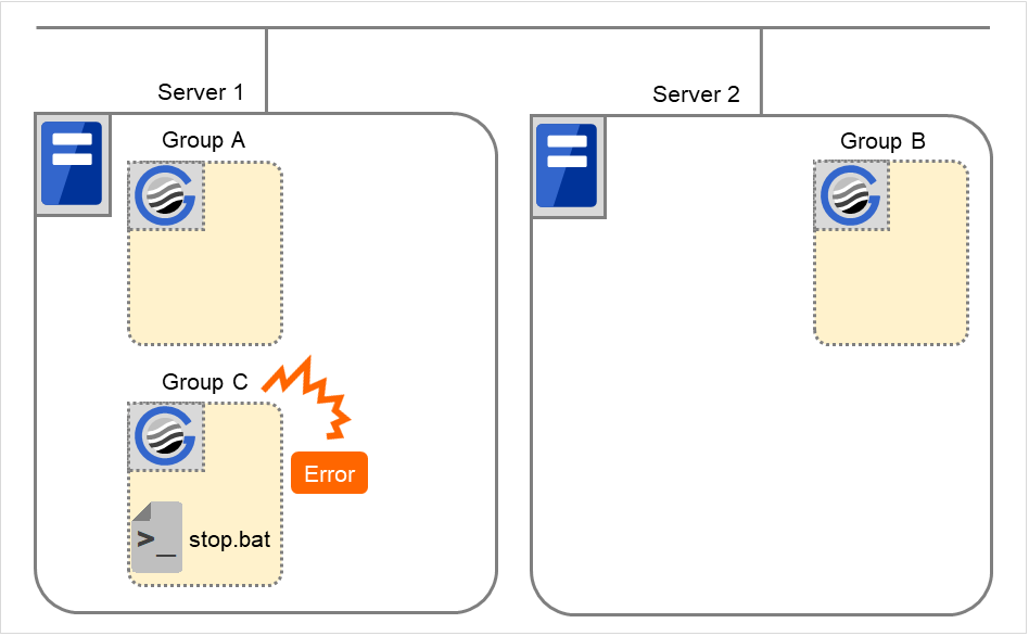
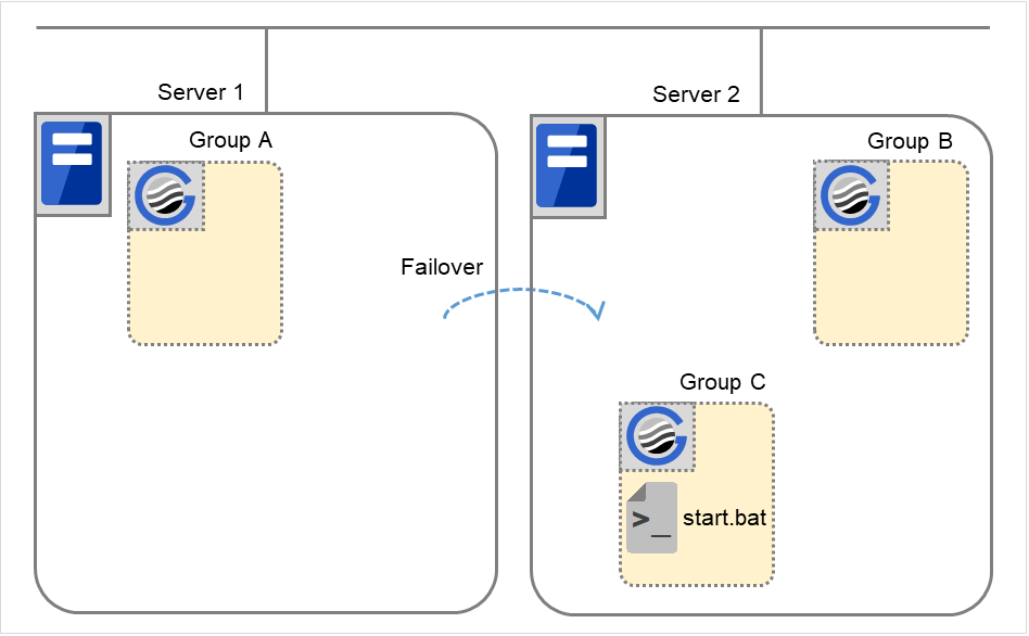
The environment variables of Server1 for stop.bat
Group C
CLP_EVENT
START
CLP_SERVER
HOME
Environment variables of Server 1 for start.bat
Group C
CLP_EVENT
RECOVER
The environment variables of Server2 for start.bat
Group C
CLP_EVENT
FAILOVER
CLP_SERVER
OTHER
9. Moving of Group C
Move the Group C that failed over to Server 2 in 8. from Server 2 to Server 1. Run the stop script on Server 2, and then run the start script on Server 1.

Fig. 3.68 Situation and script execution: moving Group C (1)
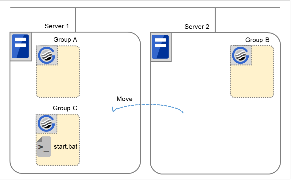
Fig. 3.69 Situation and script execution: moving Group C (2)
The environment variables for stop.bat (because of failover from 8.)
Group C
CLP_EVENT
FAILOVER
CLP_SERVER
OTHER
The environment variables for start.bat
Group C
CLP_EVENT
START
CLP_SERVER
HOME
10. Stopping Group B
The stop script of Group B is run on Server 2.
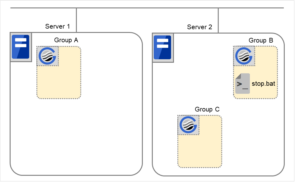
Fig. 3.70 Situation and script execution: stopping Group B
The environment variables for stop.bat
Group B
CLP_EVENT
START
CLP_SERVER
HOME
11. Starting Group B
The start script of Group B is run on Server 2.

Fig. 3.71 Situation and script execution: starting Group B
The environment variables for start.bat
Group B
CLP_EVENT
START
CLP_SERVER
HOME
12. Stopping Group C
The stop script of Group C is run on Server 2.

Fig. 3.72 Situation and script execution: stopping Group C
The environment variables for stop.bat
Group C
CLP_EVENT
FAILOVER
CLP_SERVER
OTHER
13. Starting Group C
The start script of Group C is run on Server 2.
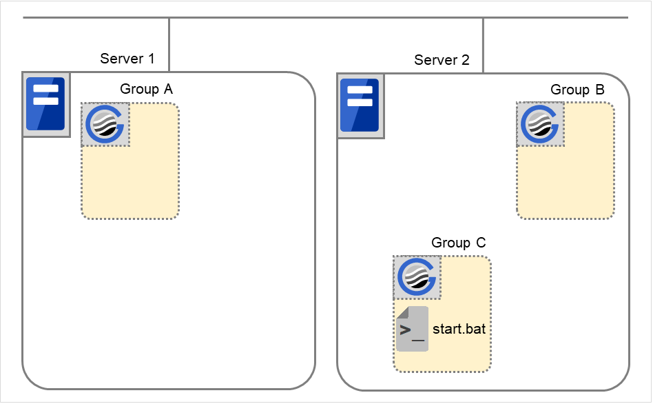
Fig. 3.73 Situation and script execution: starting Group C
The environment variables for start.bat
Group C
CLP_EVENT
START
CLP_SERVER
OTHER
Additional information 1
For a group that has three or more servers specified in the failover policy to behave differently on servers other than the primary server, use CLP_PRIORITY instead of CLP_SERVER (HOME/OTHER).
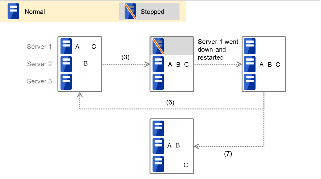
Fig. 3.74 Example of cluster status transition: failover due to server down
Example 1: "3. Failover at the failed Server 1" in the cluster status transition diagram
A group has Server 1 as its primary server. If an error occurs on Server 1, the group's start script is run on Server 2 that has next highest priority failover policy. You need to write CLP_EVENT(=FAILOVER) as the branching condition for triggering applications' startup and recovery processes (such as database rollback) in the start script in advance.
For a process to be performed only on the server that has the second highest priority failover policy, you need to write CLP_PRIORITY(=2) as the branching condition.
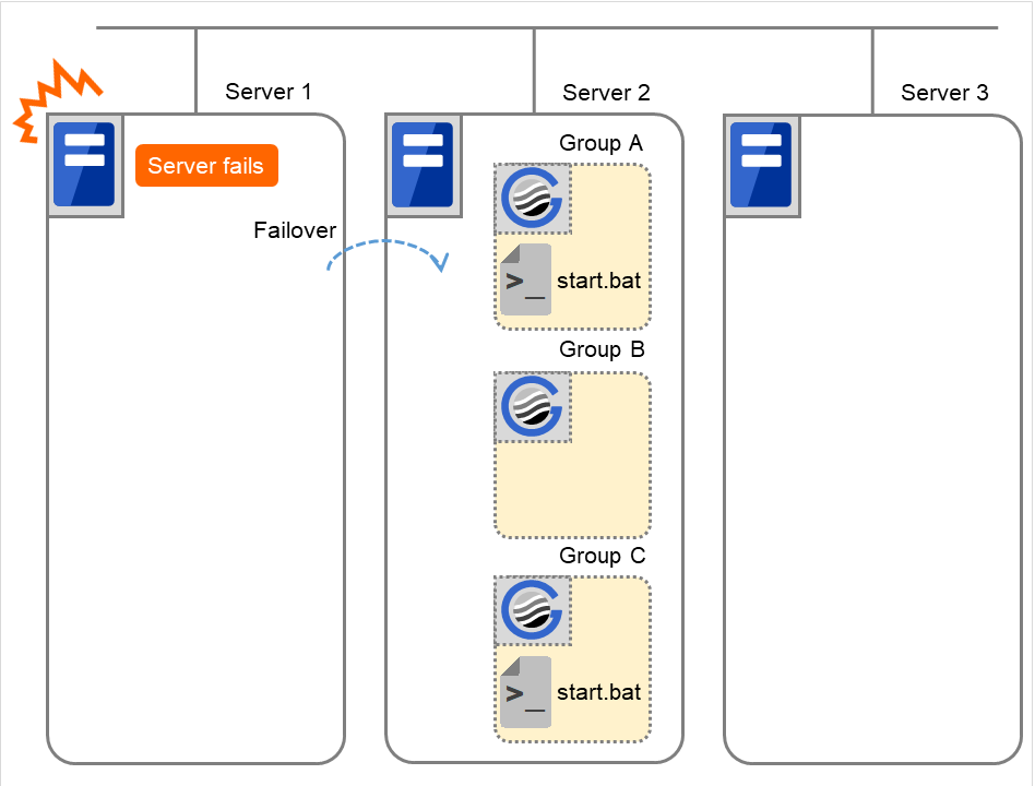
Fig. 3.75 Situation and script execution: starting Groups A and C
Environment variables for start.bat
Group A
Group C
CLP_EVENT
FAILOVER
FAILOVER
CLP_SERVER
OTHER
OTHER
CLP_PRIORITY
2
2
Example 2: "6. Moving of Group A and C" in the cluster status transition diagram

Fig. 3.76 Example of cluster status transition: moving Group C
After the stop scrip of Group C is run on Server 2 from which the group failed over, the start script is run on Server 3.
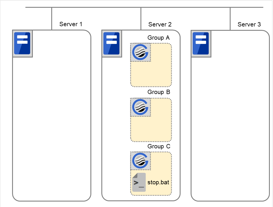
Fig. 3.77 Situation and script execution: moving Group C (1)
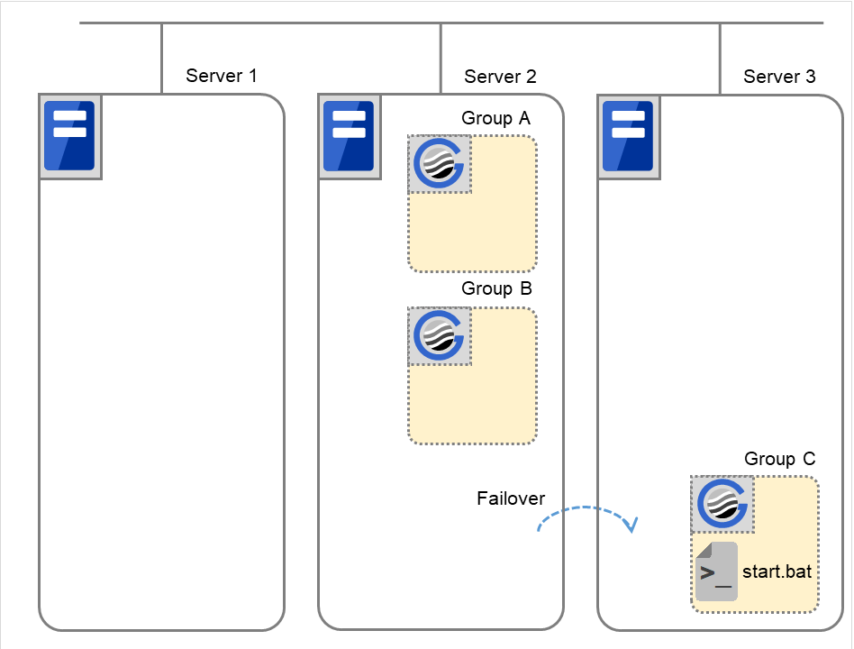
Fig. 3.78 Situation and script execution: moving Group C (2)
Environment variables for stop.bat
Group C
CLP_EVENT
FAILOVER
CLP_SERVER
OTHER
CLP_PRIORITY
2
Environment variables for start.bat
Group C
CLP_EVENT
START
CLP_SERVER
OTHER
CLP_PRIORITY
3
Additional information 2
When a monitor resource or ARMLOAD command starts or restarts a script:
The environment variables to run a start script when a monitor resource or ARMLOAD command detected an error in application are as follows:
Example 1: a monitor resource or ARMLOAD command detected an error and restarts Group A on the Server 1.
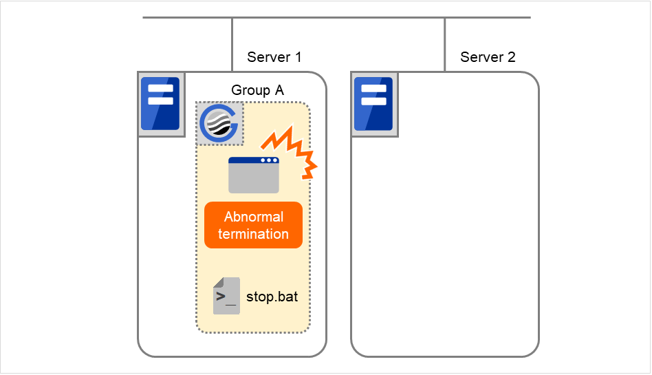
Fig. 3.79 Situation and script execution: restarting Group A (1)
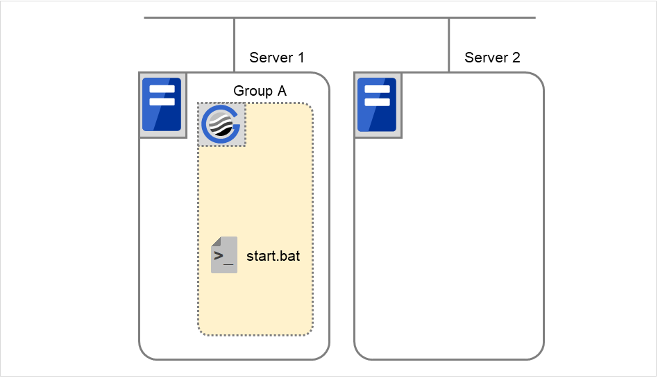
Fig. 3.80 Situation and script execution: restarting Group A (2)
Environment variable for stop.bat
Group A |
|
|---|---|
CLP_EVENT |
The same value as when the start script is run |
Environment variable for start.bat
Group A |
||
|---|---|---|
CLP_EVENT |
RECOVER |
|
CLP_EVENT |
Start |
* start.bat is executed twice.
Example2: a monitor resource or ARMLOAD command detected an error and restarts Group A on Server 2 through failover to Server 2.

Fig. 3.81 Situation and script execution: failover of Group A (1)

Fig. 3.82 Situation and script execution: failover of Group A (2)
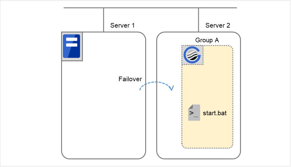
Fig. 3.83 Situation and script execution: failover of Group A (3)
Environment variable for stop.bat
Group A |
|
|---|---|
CLP_EVENT |
The same value as when the start script is run |
Environment variable for start.bat
Group A |
||
|---|---|---|
CLP_EVENT |
RECOVER |
|
CLP_EVENT |
FAILOVER |
Supplementary information 3
With Execute on standby server of Script Resource Tuning Properties enabled, start and stop scripts can also be executed on another server (standby server) that does not start a group in accordance with the timings of running these scripts on the active server that started a group.
Compared with the script execution on the active server, that on the standby server has the following characteristics:
The results (error codes) of executing the scripts do not affect the group-resource statuses.
No script before and after activation/deactivation is executed.
Monitor resources set for monitoring at activation are not started or stopped.
Different types and values of environment variables are set. (Refer to "Environment variables in script of script resource" as described above.)
The following describes the relationships between the execution timings of scripts on the standby server and the environment variables--with cluster status transition diagrams.
<Cluster status transition diagram>
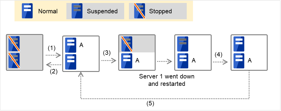
Fig. 3.84 Example of cluster status transition: failover due to server down
Numbers 1. to 5. in the diagram correspond to the following descriptions:
Normal startup
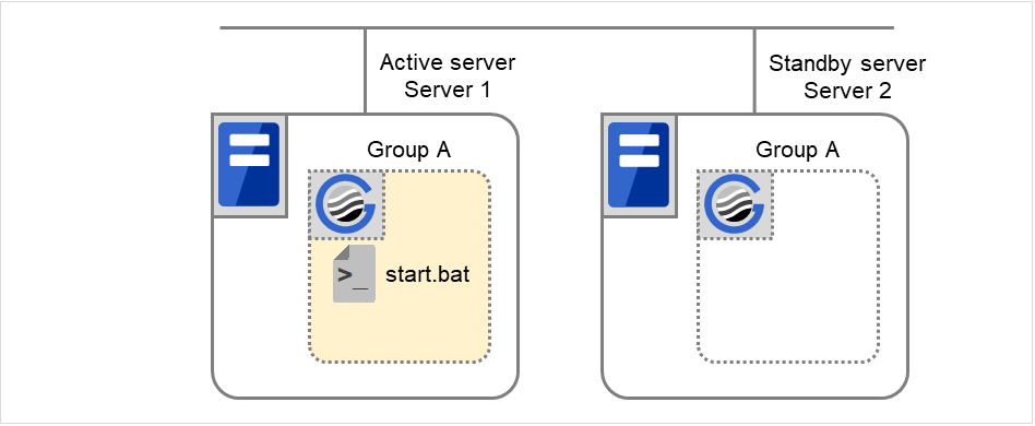
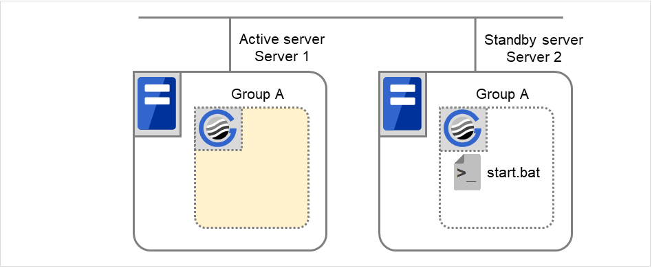
Normal shutdown
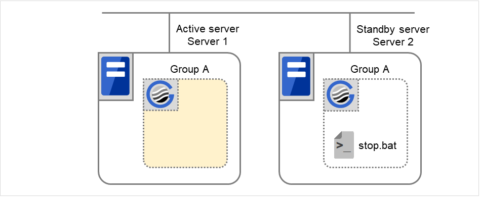
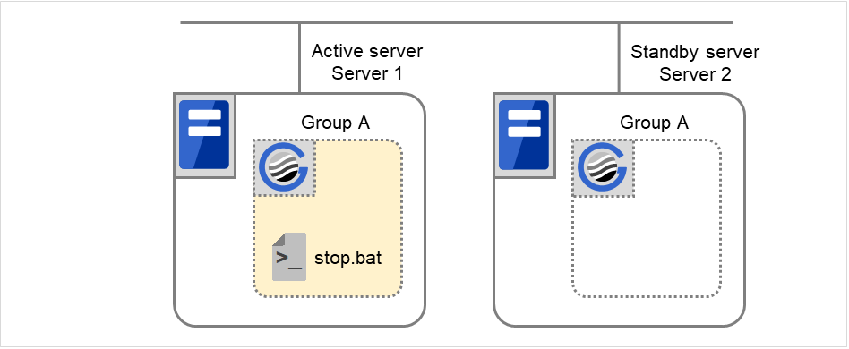
Failover at Server 1 down
With Server 1 crashed, the start script is not run on it as the standby server.
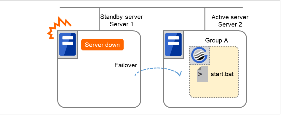
Fig. 3.89 Example of cluster status transition: failover due to server down
Environment variables for start.bat
Server 2
CLP_EVENT
FAILOVER
CLP_SERVER
OTHER
Recovering Server 1 to cluster
In this case, the start script is executed in Server 1, but not in Server 2.
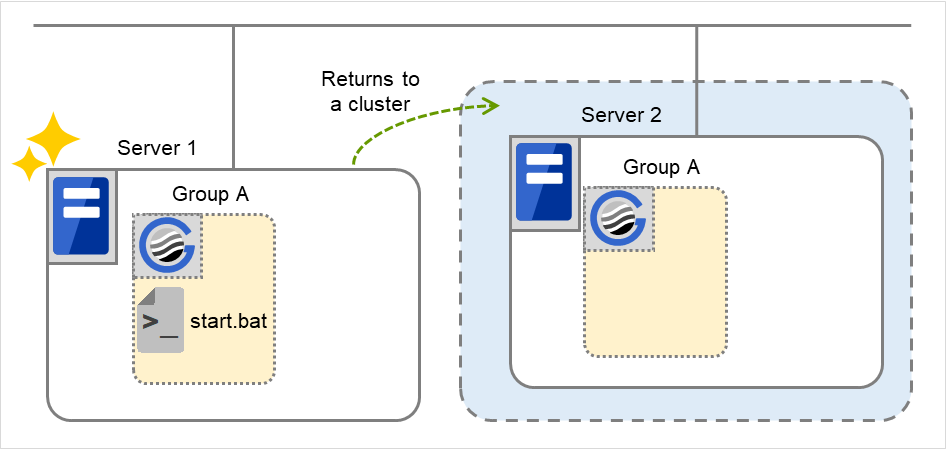
Fig. 3.90 Situation and script execution: returning a server to the cluster
Environment variables for start.bat
Server 1
CLP_EVENT
RECOVER
CLP_SERVER
HOME
Moving of Group A
The stop script for Group A is executed on Server 1 (= standby server) and Server 2 (= active server). Then the start script is run on Server 1 (= active server) and Server 2 (= standby server).
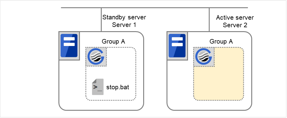
Fig. 3.91 Situation and script execution: moving Group A (1)
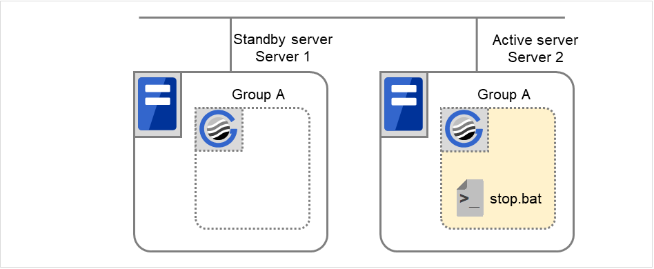
Fig. 3.92 Situation and script execution: moving Group A (2)
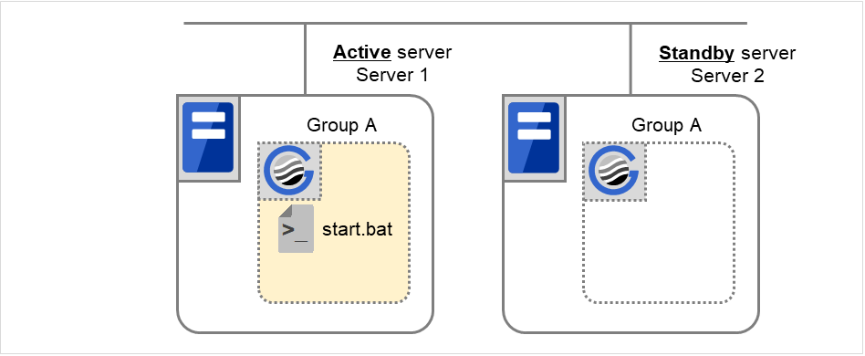
Fig. 3.93 Situation and script execution: moving Group A (3)
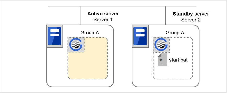
Fig. 3.94 Situation and script execution: moving Group A (4)
Environment variables for stop.bat
Server 1
Server 2
CLP_EVENT
STANDBY
FAILOVER 5
CLP_SERVER
HOME
OTHER
- 5
The value of an environment variable for the stop script is changed to that for the last executed start script. In the transition case of "5. Moving of Group A", FAILOVER is applied without a cluster shutdown immediately preceding, or START is applied with a cluster shutdown done before the phase of "5. Moving of Group A".
Environment variables for start.bat
Server 1
Server 2
CLP_EVENT
START
STANDBY
CLP_SERVER
HOME
OTHER
3.10.5. Writing scripts
This section describes how you actually write script codes in association with timing to run scripts as mentioned in the previous topic.
Numbers in brackets "(number)" in the following example script code represent the actions described in "Execution timing of script resource scripts".
Group A start script: a sample of start.bat
rem **************************************************************
rem *                          START.BAT                         *
rem **************************************************************

rem Refer to the environment variable of the script execution factor to determine the subsequent process.
IF "%CLP_EVENT%"=="START" GOTO NORMAL
IF "%CLP_EVENT%"=="FAILOVER" GOTO FAILOVER
IF "%CLP_EVENT%"=="RECOVER" GOTO RECOVER


rem EXPRESSCLUSTER is not working.
GOTO no_arm


:NORMAL
IF "%CLP_DISK%"=="FAILURE" GOTO ERROR_DISK

    rem Here, write the normal startup process of the operation.
    rem This process is to be performed at the timing of the following:
    rem
    rem (1) Normal startup
    rem (6) Moving of Group A and C (online failback)
    rem


rem Refer to the environment variable of the execution server to determine the subsequent process.
IF "%CLP_SERVER%"=="OTHER" GOTO ON_OTHER1

    rem Here, write a process to be performed only for
    rem the normal startup of the operation on the primary server.
    rem This process is to be performed at the timing of the following:
    rem
    rem (1) Normal startup
    rem (6) Moving of Groups A and C (online failback)
    rem

GOTO EXIT


:ON_OTHER1

rem Here, write a process to be performed only for
rem the normal startup of the operation on a non-primary server.


GOTO EXIT


:FAILOVER

rem Refer to the environment variable of DISK connection information to perform error handling.
IF "%CLP_DISK%"=="FAILURE" GOTO ERROR_DISK

    rem Write the startup process of the operation on the failover destination server.
    rem This process is to be performed at the timing of the following:
    rem
    rem (3) Failover at the failed Server 1
    rem


rem Refer to the environment variable of the execution server to determine the subsequent process.
IF "%CLP_SERVER%"=="OTHER" GOTO ON_OTHER2

    rem Write a process to be performed only for the startup of
    rem the operation on the primary server after the failover.

GOTO EXIT


:ON_OTHER2

rem Write a process to be performed only for the startup of
rem the operation on a non-primary server after the failover.
rem This process is to be performed at the timing of the following:
rem
rem (3) Failover at the failed Server 1
rem

GOTO EXIT


:RECOVER

rem Write a recovery process to be performed after returning to the cluster.
rem This process is to be performed at the timing of the following:
rem
rem (4) Recovering Server 1 to cluster
rem

GOTO EXIT


:ERROR_DISK

rem Write a disk-related error-handling process.

:no_arm

:EXIT
exit
Group A stop script: a sample of stop.bat
rem **************************************************************
rem *                          STOP.BAT                          *
rem **************************************************************

rem Refer to the environment variable of the script execution factor to determine the subsequent process.
IF "%CLP_EVENT%"=="START" GOTO NORMAL
IF "%CLP_EVENT%"=="FAILOVER" GOTO FAILOVER


rem EXPRESSCLUSTER is not working.
GOTO NO_ARM


:NORMAL
rem Refer to the environment variable of DISK connection information to perform error handling.
IF "%CLP_DISK%"=="FAILURE" GOTO ERROR_DISK

    rem Here, write the normal end process of the operation.
    rem This process is to be performed at the timing of the following:
    rem
    rem (2) Normal shutdown
    rem


rem Refer to the environment variable of the execution server to determine the subsequent process.
IF "%CLP_SERVER%"=="OTHER" GOTO ON_OTHER1

    rem Here, write a process to be performed only for
    rem the normal process of the operation on the primary server.

    rem This process is to be performed at the timing of the following:
    rem
    rem (2) Normal shutdown
    rem

GOTO EXIT


:ON_OTHER1

rem Write a process to be performed only for the normal end
rem of the operation on a non-primary server.

GOTO EXIT


:FAILOVER

rem Refer to the environment variable of DISK connection information to perform error handling.
IF "%CLP_DISK%"=="FAILURE" GOTO ERROR_DISK

    rem Write the normal end process to be performed after the failover.
    rem This process is to be performed at the timing of the following:
    rem
    rem (5) Cluster shutdown after failover of Server 1
    rem (6) Moving of Group A and C
    rem


rem Refer to the environment variable of the execution server to determine the subsequent process.
IF "%CLP_SERVER%"=="OTHER" GOTO ON_OTHER2

    rem Write a process to be performed only for the end of
    rem the operation on the primary server after the failover.

GOTO EXIT


:ON_OTHER2

rem Write a process to be performed only for the end of
rem the operation on a non-primary server after the failover.
rem This process is to be performed at the timing of the following:
rem
rem (5) Cluster shutdown after failover of Server 1
rem (6) Moving of Group A and C
rem

GOTO EXIT


:ERROR_DISK

rem Write a disk-related error-handling process.

:NO_ARM

:EXIT
exit
3.10.6. Tips for creating scripts
The clplogcmd command, though which message output on the alert log is possible, is available.
3.10.7. Notes on script resources
Stop the processing by using the exit command in the script activated through the start command, when the start command is used in the start/stop script.
3.10.8. Details tab
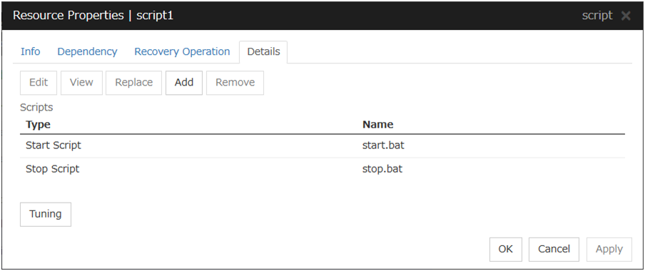
Add
Use this button to add a script other than start.bat script and stop.bat script.
Note
Do not use 2-byte characters for the name of a script to be added.Do not use "& (ampersand)" nor "= (equal mark)" for the name of a script to be added.
Remove
Use this button to delete a script. The start.bat script and stop.bat script cannot be deleted.
View
Use this button to display the selected script file.
Edit
Use this button to edit the selected script file. Click Save to apply the change. You cannot rename the script file
Replace
Opens the Open dialog box, where you can select a file.
Note
The file will not be deleted even if you delete a script file from the Cluster WebUI. If the cluster configuration data is reloaded by restarting the Cluster WebUI after deleting the script file, the deleted script file will be displayed in the Scripts.
The content of the script file selected in the Resource Properties is replaced with the one selected in the Open dialog box. If the selected script file is being viewed or edited, replacement cannot be achieved. Select a script file, not a binary file such as an application program.
Tuning
Open the Script Resource Tuning Properties dialog box. You can make advanced settings for the script resource.
Script Resource Tuning Properties
Parameter tab
Display the details of setting the parameter.
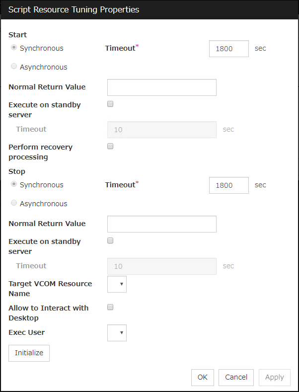
Common to all start scripts and stop scripts
Synchronous
Select this button to wait for a script to end when it is run.
Asynchronous
This cannot be selected.
Normal Return Value (Within 1023 bytes)
Configure what error code from the script is normal.
Values can be separated by commas (for example, 0, 2, 3).
Values can be specified using a hyphen (for example, 0-3).
Note
When specifying a value to Normal Return Value, set the same value to start script and stop script.An error cannot be detected when 1 is specified as Normal Return Value because 1 is returned when an error occurs with cmd.exe which executes the script.
Execute on standby server
Set whether the scripts are to be executed on the standby server. Enabling this parameter allows you to specify the timeout value (1 to 9999) for the execution.
Perform recovery processing
Specify whether to run a start script or not in any of the following timings:
When the server is recovered
When a monitor resource/ARMLOAD command error is detected
When the group resource activation terminates due to an error
For more information, confirm with "Execution timing of script resource scripts" in this guide. When executed as the recovery operation, RECOVER is set for CLP_EVENT, the environment variable.
Timeout (1 to 9999)
When you want to wait for a script to end (when selecting Synchronous), specify how many seconds you want to wait before a timeout. This box is enabled when Synchronous is selected. If the script does not complete within the specified time, it is determined as an error.
Target VCOM Resource Name
Configure this to use a virtual computer name as a computer name used for script resources. Virtual computer names and resource names that exist in a failover group to which script resources belong are listed.When you specify this parameter, add the following environment variables and then start the script:COMPUTERNAME=<virtual computer name>_CLUSTER_NETWORK_FQDN_=<virtual computer name>_CLUSTER_NETWORK_HOSTNAME_=<virtual computer name>_CLUSTER_NETWORK_NAME_=<virtual computer name>Note
When Target VCOM Resource Name is specified, the EXPRESSCLUSTER commands cannot be used in a script.
Allow to Interact with Desktop
Specify whether to allow the script to be run to communicate with desktop. If this is selected, progress status of the script can be checked on the screen. It is effective if used when debugging the script.
Exec User
Select a user by whom the script is to be executed, from users registered in the Account tab of Cluster Properties.If no user is specified, the script is run by the local system account.
Initialize
Click Initialize to reset the values of all items to their default values.
3.11. Understanding disk resources
3.11.1. Dependencies of disk resources
By default, this function does not depend on any group resource type.
3.11.2. Disk resources
A disk resource refers to a switching partition on a shared disk accessed by more than one server that constitutes a cluster.
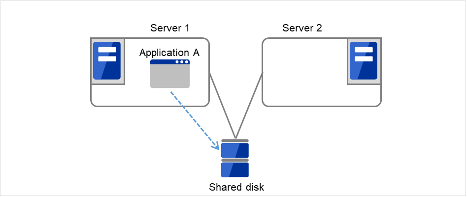
Fig. 3.95 Disk resource (1)
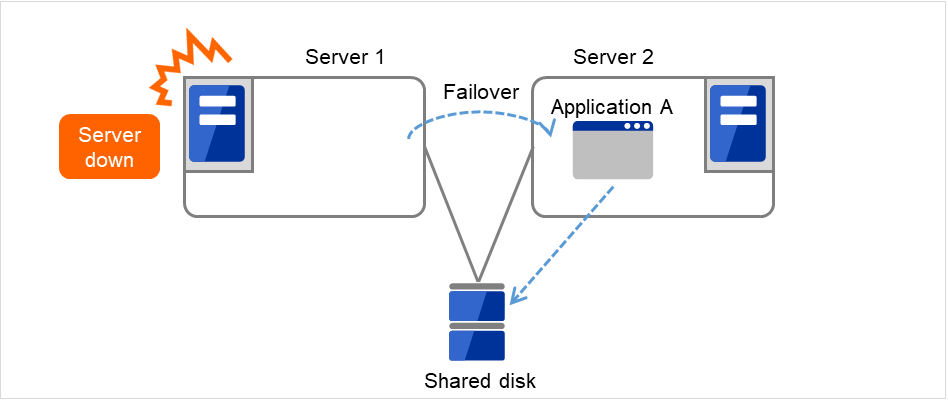
Fig. 3.96 Disk resource (2)
3.11.3. Notes on disk resources
Make settings so that the same partition is accessible with the same drive letter on all servers. Even if the drive letter automatically assigned by the OS is the same as the one that you want to assign, be sure to manually assign the drive letter explicitly; for example, by deleting the OS assigned drive letter and then assigning the desired drive letter.
If a drive letter different from the one used on partition is set, the drive letter will be changed when the disk resource is started up. If the drive letter is used on other partitions, starting up the disk resource will fail.
Dynamic disk is not supported. If a partition on dynamic disk is used for disk resource, starting up the disk resource will fail.
<Troubleshooting>
Run the following command at the command prompt to remove the drive character:
# mountvol drive_character (of_change_target): /P
Check that the drive character is removed from the change target drive by using (Control Panel > Administrative Tools > Computer Management > Disk Management).
Add the drive character from Disk Management.
3.11.4. Details tab
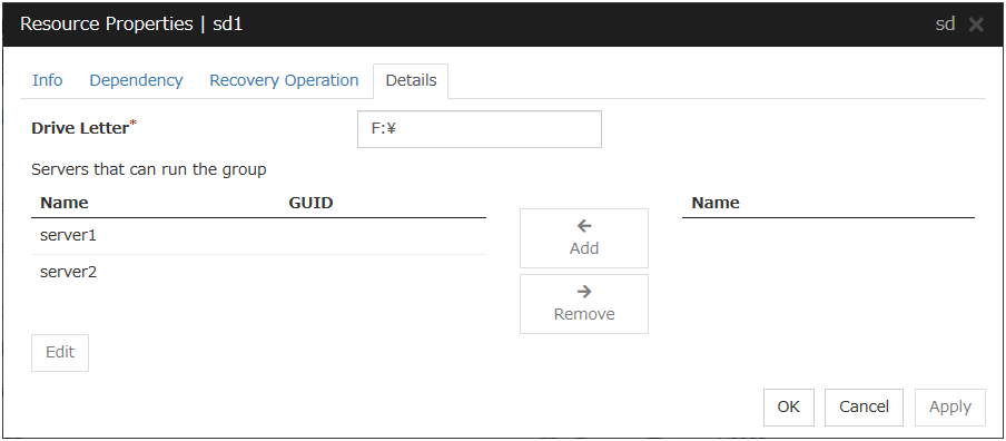
Drive Letter (Within 1023 bytes)
Specify the drive letter (A to Z) for the disk to be used.
Add
Use this button to add a server to Servers that can run the group. The list of added server partitions is displayed in the Selection of Partition dialog box.
Remove
Use this button to delete a server from Servers that can run the group.
Edit
The Selection of Partition dialog box of the selected server is displayed.
Important
For a partition specified by disk resource, specify the partition on the shared disk that is connected to the filtering configured HBA.Make sure not to specify a partition specified by disk resource to partition for disk heartbeat resource, or cluster partition or data partition for mirror disk resource. Data on the shared disk may be corrupted.
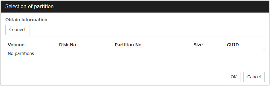
3.12. Understanding service resources
You can register services managed by EXPRESSCLUSTER and run when starting, stopping, failing over, or moving groups in EXPRESSCLUSTER. It is also possible to register your own services to service resources.
3.12.1. Dependencies of service resources
By default, this function depends on the following group resource types.
Group resource type |
|---|
Floating IP resource |
Virtual IP resource |
Virtual computer name resource |
Disk resource |
Mirror disk resource |
Hybrid disk resource |
Print spooler resource |
Registry synchronization resource |
CIFS resource |
NAS resource |
AWS elastic ip resource |
AWS virtual ip resource |
AWS DNS resource |
Azure probe port resource |
Azure DNS resource |
3.12.2. Service resources
A service resource refers to a service managed by the OS service control manager.
3.12.3. Notes on service resources
Service executed in service resource must be installed on all servers in failover policy.
Generally, the service executed by the service resource is set to manual start. In case of the service which is executed by automatic start or the service which may be executed by other than the service resource, it is necessary to check on Do not assume it as an error when the service is already started which is described below in Service tab of Service resource tuning properties dialog. If this check box is off, activation fails when executing service start processing by the service resource to the service which has already been executed.
If the Service tab of the Service resource tuning properties dialog box shows the checked Do not assume it as an error when the service is already started check box and the corresponding service has already been started at the service resource activation, the service is not stopped at the service resource deactivation.
- The service executed by the service resource is not controlled by applications other than EXPRESSCLUSTER. Therefore, it is recommended to set the recovery operation not to be performed by the service control manager.If a service is set to restart upon the recovery operation by the service control manager, an unexpected action might be performed due to duplication with the recovery operation by EXPRESSCLUSTER.
3.12.4. Details tab
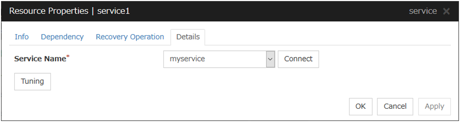
Service Name (Within 1023 bytes)
Specify the service name or service display name used in the service resource.
Combo box options display the list of the service display names of the services collected from the server.
Connect
Collects the service list from all the servers and updates the service display name list to be displayed in the Service Name combo box.
Tuning
Use this button to display the Service Resource Tuning Properties dialog box. You can make advanced settings for the service resource.
Service resource tuning properties
Parameter tab
The detailed setting for parameters is displayed.
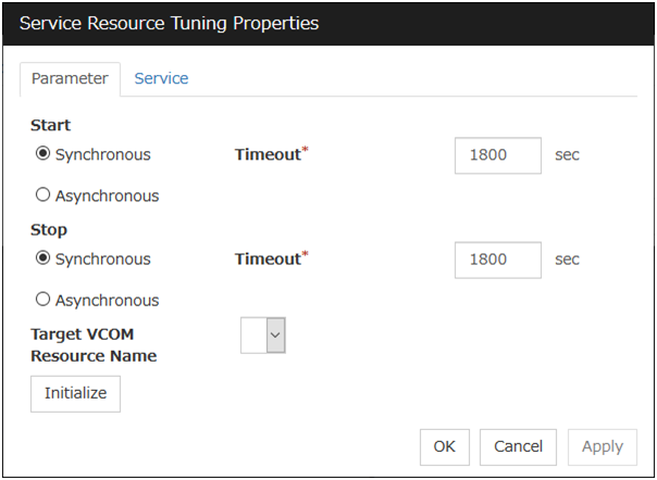
Synchronous
When the service is started up, it waits for "Started". Typically, the status changes from "Stopping" to "Started" when the service is started.
When stopping the service, it waits for that the status of service becomes "Stopped". Typically, the status changes from "Stopping" to "Stopped" when the service is stopped.
Asynchronous
No synchronization is performed.
Timeout (1 to 9999)
Specify the timeout for the status of the service to become "Started" at the time starting the service. The timeout can be specified only when Synchronous is selected. If the status of the service does not change to "Started" within the timeout, it is determined as an error.
Specify the timeout for the stats of the service to become "Stopped" at the time stopping the service. The timeout can be specified only when Synchronous is selected. If the status of the service does not change to "Stopped" within the timeout, it is determined as an error.
Target VCOM Resource Name
Configure this to use a virtual computer name as a computer name used for the service resource. The virtual computer name and resource name that exist in a failover group which the service resource belongs to are listed.When you specify this parameter, add the following registry and then start the service:Key name
HKEY_LOCAL_MACHINE\SYSTEM\CurrentControlSet\Services\<service set by service resource>
Value
Name : EnvironmentType : REG_MULTI_SZData : COMPUTERNAME=<virtual computer name>_CLUSTER_NETWORK_FQDN_=<virtual computer name>_CLUSTER_NETWORK_HOSTNAME_=<virtual computer name>_CLUSTER_NETWORK_NAME_=<virtual computer name>
Initialize
Click Initialize to reset the values of all items to their default values.
Service tab
The settings for the service are displayed.
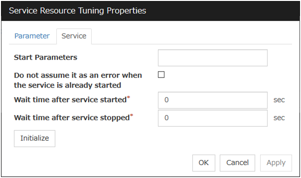
Start Parameters (Within 1023 bytes)
Specify a parameter for the service. When there are multiple parameters, leave a space between parameters. For a parameter that includes a space, enclose the parameter by double quotation marks. Note that backslash \ cannot be used.
Example: "param 1" param2
Do not assume it as an error when the service is already started
Wait time after service started (0 to 9999)
Specify the time to wait after the service is started.The service resource activation will be completed after waiting for the specified time.
Wait time after service stopped (0 to 9999)
Specify the time to wait after the service is stopped.The service resource deactivation will be completed after waiting for the specified time.
Initialize
Click Initialize to reset the values of all items to their default values.
3.13. Understanding print spooler resources
3.13.1. Dependencies of print spooler resources
By default, this function depends on the following group resource types.
Group resource type |
|---|
Disk resource |
Mirror disk resource |
Hybrid disk resource |
3.13.2. Print spooler resources
Print spooler resources make the printer functions failover by creating a spool directory on the partition of the disk resource or mirror disk resource.
3.13.3. Notes on print spooler resources
All servers should use the same printer name, same port and same shared name in their printer definitions and configure the settings for local printer.
Set the spool directory on a partition of a disk resource or mirror disk resource because the printer spool directory should fail over.
When a failover occurs, the print spooler resource on the standby server stops the Print Spooler service. Depending on this stop timing, not-printed data may remain in the printer. In this situation, a printing job newly started from the failover destination (standby server) may become invalid because of the not-printed data remaining in the printer. Therefore, use the printer for a failover only from the active server.
In case using the printer device directly connected to the basic processing device as the fail over target printer device, set the status of the printer device connected to the waiting server "not in use."
In case that using the fail over target printer device from the waiting server is necessary, create a new printer and use the printer as a different printer name from the fail over target printer. Printing operation is not guaranteed when using the fail over target printer. Configure and operate the printer referring to the following chart.
Configured automatically printing out to the printer device.
Not configured automatically printing out to the printer device.
printer directly connectedto the basic processing device
printer directly connected to the network (*)
printer directly connected to the basic processing device
Printing only from the operating server
Auto switching enabled. (1)
Auto switching enabled. (2)
Auto switching enabled. (1)
Printing also from the waiting server
Auto switching enabled. (3)
Auto switching enabled. (3)
Auto switching not enabled. (4)
Note
Automatic printing out should be enabled because automatic printing out setting is enabled with printer devices which can be connected to the network.
After the error is deleted from the operating server, by re-combining the server to the cluster and restarting the cluster, the status of the documents which are the print share target of the waiting server before fail over and have been output to the printer spool become as follows.
Printing from the server AP
Printing from the client AP
Stop printing at failover, restart printing when the cluster returns.
Stop printing at failover, restart printing when the cluster returns.
The documents which were being printed on the operating server are printed on the waiting server by fail over occurrence. This time, the pages which have already been printed on the operating server are printed again because the printing starts from the top page of the documents on the waiting server. Also, the printing of the documents which were being printed to the printer which is not registered to the cluster on the waiting server starts from the top of the document at fail over.
The maximum number of printers which can be registered to one cluster system is 128.
If the printer is not recognized, resource activation may fail. The printer is recognized by using the Print Spooler service. Therefore, make sure that the Print Spooler service has started and then specify Auto for the startup type.
When the cluster is started by starting the OS, the print spooler resource starts before the printer is recognized, depending on the OS and cluster processing timing. This may lead to a resource activation failure. Should this event occur, set a value of 1 or more for Retry Count at Activation Failure.
3.13.4. Details tab
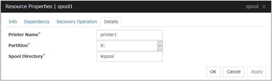
Printer Name (Within 220 bytes)
Specify the printer name to be used.
Partition (Within 7 bytes)
Select a drive letter for the spool directory. Select a drive letter on disk resource or mirror disk resource.
Spool Directory (Within 244 bytes)
Specify a path for the spool directory. Specify a path after the drive letter starting with a back slash \.
Example: \PRINTER\SPOOL
3.14. Understanding virtual computer name resources
3.14.1. Dependencies of virtual computer name resources
By default, this function depends on the following group resource types.
Group resource type |
|---|
Floating IP resource |
Virtual IP resource |
AWS elastic ip resource |
AWS virtual ip resource |
Azure probe port resource |
3.14.2. Virtual computer name resources
Client applications can be connected to a cluster server by using a virtual computer name. The servers can be connected to each other by using a virtual computer name. By using a virtual computer name, switching from one server to the other to which a client is connecting remains transparent even if failover or moving of a failover group occurs.
Only client applications on Windows machine can connect to the cluster server by a virtual computer name.
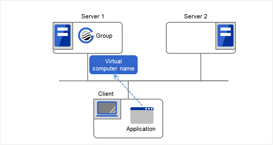
Fig. 3.97 Virtual computer name resource (1)
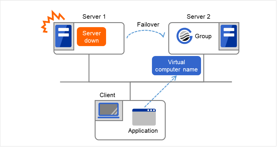
Fig. 3.98 Virtual computer name resource (2)
3.14.3. Determining virtual computer name
A computer name used as a virtual computer name should satisfy the following conditions:
The name should be different from cluster server names.
The name should be different from any computer names of machines connected to the same network segment.
The name should be within 15 characters.
The name should consist of letters from alphabet, numbers, and/or hyphen.
The name is not case-sensitive.
3.14.4. Linking virtual computer name and floating IP address
Once a virtual computer name is linked with a floating IP address, the combination of the virtual computer name and floating IP address can be written to the client's LMHOSTS file. To configure this, use the config mode of Cluster WebUI. Select Virtual Computer Name Resource Properties, and click Details tab, and then click Target FIP Resource Name. This configuration allows using the virtual computer name from a remote LAN.
If the virtual computer name and floating IP address are not linked, the virtual computer name cannot be used from a remote LAN by using LHMOSTS file. In this case, virtual computer name needs to be registered to DNS dynamically, or WINS needs to be set to use virtual computer names from a remote LAN. For information on how to configure WINS, refer to the next section "Configuring WINS server."
3.14.5. Configuring WINS server
To use a virtual computer name from a remote LAN without linking the virtual computer name to a floating IP address, set the WINS server as follows:
When installing the WINS server to cluster servers
Install the WINS server on all servers in a cluster. If you are prompted to reboot the servers after installation, click No.
Configure the settings described from step 3 to 6 on all cluster servers.
Open Control Panel and double-click Network Connections. Double-click Local Area Connection and open Local Area Connection Properties.
Click Internet Protocol (TCP/IP) and click Properties.
Click Advanced and click WINS tab.
Add the IP addresses of public LAN in all servers in a cluster to the WINS address (The order of usage does not matter.)
Shut down and reboot the cluster.
Install the WINS server on the client on a remote LAN by following the same steps.
When setting the WINS server on a server other than a cluster server
Install WINS server on a server other than a cluster server.
Open Control Panel and double-click Network Connections. Double-click Local Area Connection and open Local Area Connection Properties.
Click Internet Protocol (TCP/IP) and click Properties.
Click Advanced and click WINS tab.
In WINS addresses, add the IP addresses of WINS server.
Repeat the steps above for all servers in the cluster.
Shut down and reboot the cluster.
Install the WINS server to the client on a remote LAN by following the same steps.
3.14.6. Appropriate use of virtual computer name resources and dynamic DNS resources
Virtual computer name resources use an old protocol. If a DNS server is available, Dynamic DNS resources are recommended.
Virtual computer name resources cannot be used together with dynamic DNS resources.
3.14.7. Services available to the virtual computer name
The following services are available to the virtual computer name:
Service |
FIP linked |
FIP n/at linked |
|---|---|---|
TCP/IP name resolution (from computer name to IP address) |
✓ |
n/a |
Network drive connection |
✓ |
✓ |
Network printer connection |
✓ |
✓ |
Pipe with the name |
✓ |
✓ |
RPC (pipe with the name) |
✓ |
✓ |
RPC (TCP/IP) |
✓ |
n/a |
3.14.8. Notes on virtual computer name resources
Create a virtual computer name control process (clpvcomp.exe) per virtual computer name resource to be activated. Make sure not to stop the process by mistake. An error of process disappearance can be detected by virtual computer name monitoring resources.
The following services are not available to the virtual computer name:
Mail slot
RPC (NetBIOS)
When the virtual computer name and floating IP address are not linked, the following needs to be considered:
The following services cannot be used.
TCP/IP name resolution (from computer name to IP address)
RPC (TCP/IP)
It may take a few minutes to reconnect to the cluster after failover due to a failure of the server.
It may take a few minutes to display the virtual computer name in the network computer after the cluster is started.
The virtual computer name cannot be written to LMHOSTS.
When you have the settings to use a DNS server and the DNS server is associated with WINS, switching by failover cannot be done while cache information of the virtual computer name remaining on the DNS server. Configure the time to retain cache for WINS to approximately 1 second on the DNS server.
If the virtual computer name and floating IP address are linked, the following need to be considered:
The NetBEUI protocol cannot be used. To use the NetBEUI protocol, cancel the linkage.
The virtual computer name is valid with the network address of the linked floating IP. To use the virtual computer name from a network address other than that of the linked floating IP, perform one of the following operations:
Register the name with DNS dynamically.
Enter a combination of the virtual computer name and floating IP address in LMHOSTS.
Configure the WINS server.
Multiple virtual computer names cannot be linked to the same floating IP.
When different floating IPs exist on one or more public LAN, for using the same virtual computer name on each LAN, activation and deactivation processing needs to be executed sequentially by creating virtual computer name resource corresponding to each floating IP and setting dependency relation between these resources.
To register a virtual computer name with the WINS server on a remote network, configure the following settings in cluster servers: An example of Windows Server 2012/Windows Server 2012 R2 is given below.
Open Control Panel, and click Network and Sharing Center. Then, open Change Adapter Settings.
From the menu, click Advanced, and then click Advanced Settings. Select Adapters and Bindings tab.
- Change the order of the BindPath. The public LAN (the network adapter with which the WINS server address is registered) should be on the top.Adapters and Bindings tab should look similar to the following:
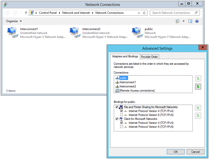
- The communication by file sharing protocol (SMB/CIFS) using a virtual computer name owned by an activated group on the active server may fail due to an authentication error.(Example 1)The Explorer is started in the server where the group is active and the following address is entered in the address bar. However it results in causing an authentication error and cannot open the shared folder.
<Virtual computer name>/shared name
(Example 2)
In a server where the group was active, started the registry editor and specified the virtual computer name in "Connect Network Registry," but failed due to authentication error.
<Troubleshooting>
Verify that the all servers are properly working from the Cluster WebUI.
Execute Steps 3 to 7 below in each server in the cluster.
From the Start menu, select Run, and run regedit.exe and add the following registry value:
HKEY_LOCAL_MACHINE\SYSTEM\CurrentControlSet\Services\lanmanserver\parameters
Name (Type):
DisableStrictNameChecking (DWORD type)
Value:
0x1
If the following value exists in the following key, delete it:
Key:
HKEY_LOCAL_MACHINE\SYSTEM\CurrentControlSet\Control\Lsa\MSV1_0
Name (Type):
BackConnectionHostNames (DWORD type)
- Create a new multi-line string value for the same the name in Step 4 (BackConnectionHostNames), and set a virtual computer name.(Example) when there are two virtual computer names: vcom1 and vcom2
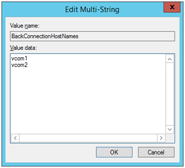
Close the registry editor.
- (applicable only when the virtual computer name and the floating IP address are linked)In the system drive: \Windows\system32\drivers\etc\hosts, add an entry of the virtual computer name (not FQDN name but computer name only) and the linked floating IP address. When there are multiple virtual computer names linked with floating IP address, add entries for all of them.(Example) when the virtual computer name is "vcom1" and the linked floating IP address is "10.1.1.11":Add the following to the hosts file: 10.1.1.11 vcom1
Execute Steps 3 to 7 above in all servers. Then shut down the cluster and reboot all servers.
Notes on registering a virtual computer name with DNS dynamically
Cluster server must be assigned in the domain.
DNS must be configured for the public LAN. EXPRESSCLUSTER registers virtual computer name specified by public LAN with DNS.
DNS registration is performed when virtual computer name resource is activated. Failure of registration will not be recognized as an error.
A virtual computer name is deleted from DNS when virtual computer name resource is deactivated. Failure of deletion will not be recognized as an error.
Since virtual computer name resource cannot be allocated to NIC when the LAN cable is not connected, the activation of the resource may fail.
When Server service of OS is stopped, virtual computer name resource cannot be activated. If you want to use virtual computer name resource, do not disable/stop Server service.
If Secure only is specified for DNS Dynamic Updates, the write and the delete subtree permissions must be applied to computer objects in the zone to be updated by a virtual computer name resource. Apply the permissions to This object and all descendant objects. For how to apply the permissions, refer to the setting method for the DNS server. The settings above are not required if Nonsecure and secure is specified for DNS Dynamic Updates.
3.14.9. Details tab
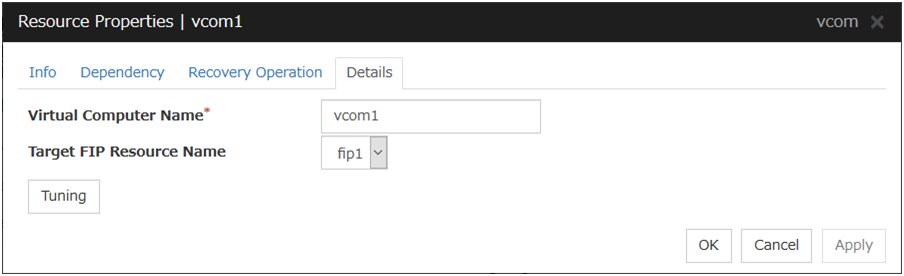
Virtual Computer Name (Within 15 bytes)
Specify the virtual computer name.
Target FIP Resource Name
Select the floating IP resource name to be linked to the virtual computer name.
Tuning
Display the VCOM Resource Tuning Properties dialog box to configure the details of virtual computer name resource.
VCOM Tuning Properties
Parameter tab
Display the details of setting the parameter.
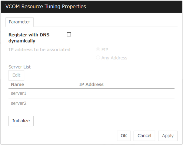
Register with DNS dynamically
Specify whether or not to register with DNS dynamically during activation of resource.
IP address to be associated
Select one of the followings as IP address for registration with DNS dynamically to associate with virtual computer name.
Edit
When Any Address is selected for IP address to be associated, select your target server in Servers. Click Edit to specify an IP address on a server basis..
Initialize
Click this button to configure default values for all options.
3.15. Understanding dynamic DNS resources
3.15.1. Dependency of dynamic DNS resources
By default, dynamic DNS resources depend on the following types of group resources.
Group resource type |
|---|
Virtual IP resource |
Floating IP resource |
AWS elastic ip resource |
AWS virtual ip resource |
Azure probe port resource |
3.15.2. Dynamic DNS resources
A dynamic DNS resource registers a virtual host name and the IP address of an activated server with the dynamic DNS server (hereafter, DDNS server). A client application can use a virtual host name to access the cluster server. Use of virtual host names allows clients to transparently switch connection from one server to another when a group is "failed over" or "moved".
The following figure shows the Dynamic DNS server (DDNS server), Servers 1 and 2, and a client. On the DDNS server, Server 1 registers the virtual host name and the IP address.
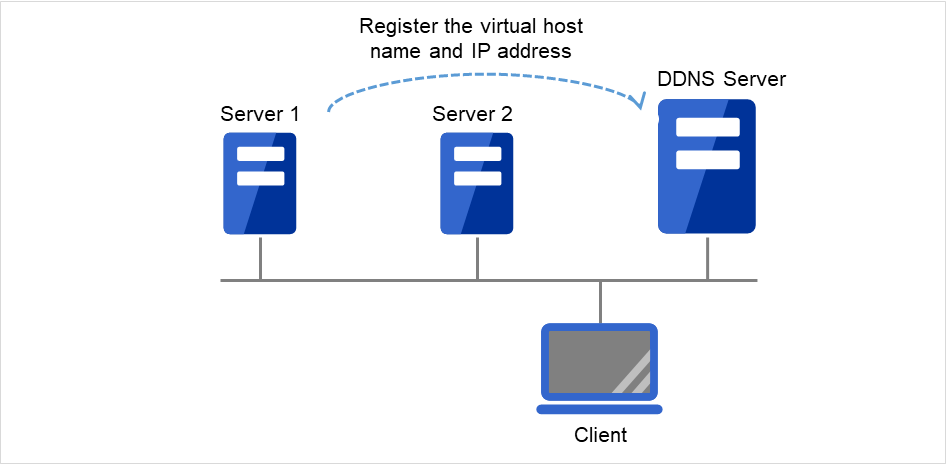
Fig. 3.99 Configuration with the DDNS server (1)
The client queries the DDNS server about the IP address (corresponding to the virtual host name) to be accessed. The DDNS server returns the IP address (corresponding to the virtual host name) of Server 1 to the client. The client then accesses the IP address of the virtual host name.
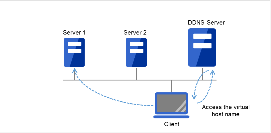
Fig. 3.100 Configuration with the DDNS server (2)
Server 1 crashes, and a failover to Server 2 occurs.
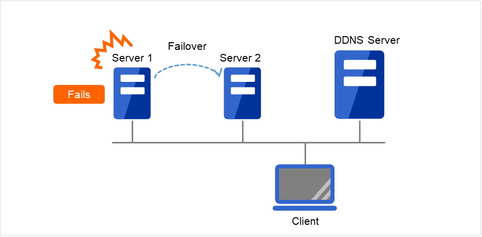
Fig. 3.101 Configuration with the DDNS server (3)
On the DDNS server, Server 2 registers the virtual host name and the IP address.
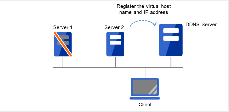
Fig. 3.102 Configuration with the DDNS server (4)
The client queries the DDNS server about the IP address (corresponding to the virtual host name) to be accessed. The DDNS server returns the IP address (corresponding to the virtual host name) of Server 2 to the client. The client then accesses the IP address of the virtual host name.
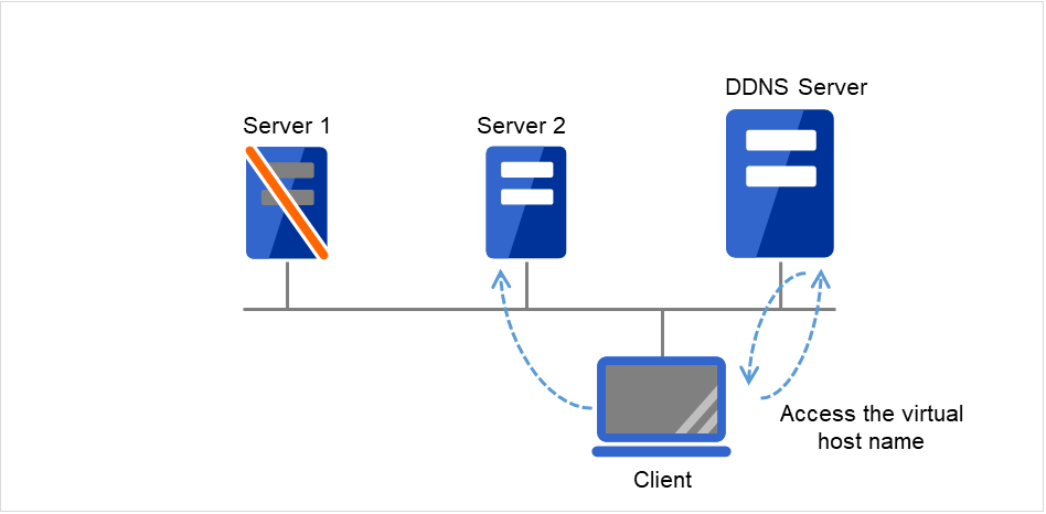
Fig. 3.103 Configuration with the DDNS server (5)
3.15.3. Appropriate use of virtual computer name resources and dynamic DNS resources
Virtual computer name resources use an old protocol. If a DNS server is available, Dynamic DNS resources are recommended.
Virtual computer name resources cannot be used together with dynamic DNS resources.
3.15.4. Preparation for use of dynamic DNS resources
To use dynamic DNS resources, you need to establish a DDNS server in advance. DDNS servers support only active directories.
If using the Kerberos authentication function, you need to make the following setting for the Active Directory domain to be updated by the dynamic DNS resource.
Please give the following permissions to each cluster server.
Create All Child Objects
Delete All Child Objects
Permissions will be applied to, please choose This object and all child objects.
If Secure only is specified for DNS Dynamic Updates, the write permissions must be applied to cluster servers in the zone to be updated by a virtual computer name resource. Apply the write permissions to This object and all child objects (This object and all descendant objects for Windows Vista or later and Windows Server 2008 or later). For how to apply the write permissions, refer to the setting method for the DNS server.
3.15.5. Notes on dynamic DNS resources
If Execute Dynamic Update Periodically is enabled, a dynamic DNS monitor resource periodically registers a virtual host name to the DDNS server.
Create a DDNS control process (clpddnsp.exe) per dynamic DNS resource to be activated. Make sure not to stop the process by mistake. An error of process disappearance can be detected by dynamic DNS monitor resources.
When the IP addresses of servers exist in different segments, FIP addresses cannot be specified as the IP addresses of dynamic DNS resources.
To register the IP addresses of servers with the DDNS server, make the setting of each IP address separately for each server. Enter the IP address of any server in the IP Address box on the Common tab and then specify the IP addresses of other servers individually on each server tab.
Regarding the settings for each server, if the same virtual host name already exists at activation, the duplicate virtual host name is temporarily deleted from the primary DNS server and the relevant virtual host name and IP address of the activated server are registered. The setting of the Delete the Registered IP Address option, which is a setting applied at deactivation, does not affect this behavior.
In client access using a virtual host name, if a group having dynamic DNS resources is failed over, reconnection (e.g. restart of the browser) may be required.
Behavior in Cluster WebUI connection using a virtual host name
- When the IP address of each server is separately specified for dynamic DNS resourcesIn client access using a virtual host name via Cluster WebUI connection, if a group having dynamic DNS resources is failed over, the Cluster WebUI connection will not be automatically switched. You need to restart the browser and to establish Cluster WebUI connection again.
- When FIP addresses are specified for dynamic DNS resourcesIn client access using a virtual host name via Cluster WebUI connection, if a group having dynamic DNS resources is failed over, the Cluster WebUI connection will be automatically switched.
3.15.6. Details tab

Virtual Host Name (Within 253 bytes)
Specify the virtual host name to be registered in the DDNS service.
IP Address (Within 79 bytes)
Specify the IP address corresponding to the virtual host name.
To use an FIP resource in parallel, specify the IP address of the FIP resource in the [Source IP Address] tab. To use the IP addresses of servers, specify each IP address in the tab of each server.
DDNS Server (Within 255 bytes)
Specify the IP address of the DDNS server. When specifying secondary DNS servers, use a comma (,) for the separator. First, specify the primary DNS server, and then specify secondary DNS servers.Examples:To specify only the primary DNS server: 192.168.10.180To specify two secondary DNS servers:192.168.10.180,192.168.10.181,192.168.10.182
Port No. (1 to 65535)
Specify the port number of the DDNS server. Its default value is 53.
Cache TTL (0 to 2147483647)
Specify the time to live (TTL) of the cache. Its default value is 0 seconds.
Execute Dynamic Update Periodically
Update Interval (1 to 9999)
Specify the interval for periodic registration of the virtual host name and the IP address of the activated server with the DDNS server. The default value is 60 minutes.
Be sure to specify a time shorter than the update interval of the DDNS server.
Delete the Registered IP Address
Kerberos Authentication
Specify whether to enable Kerberos authentication in Active Directory. No password need to be specified because a password is automatically generated when a dynamic DNS resource registers a virtual host name in the Active Directory domain. The default is cleared.
3.16. Understanding virtual IP resources
3.16.1. Dependencies of virtual IP resources
By default, this function does not depend on any group resource type.
3.16.2. Virtual IP resources
Client applications can be connected to a cluster server by using a virtual IP address. The servers can be connected to each other by using a virtual IP address. By using a virtual IP address, switching from one server to the other to which a client is connecting remains transparent even if failover or moving of a failover group occurs. The graphic in the next page shows how virtual IP resources work in the cluster system.
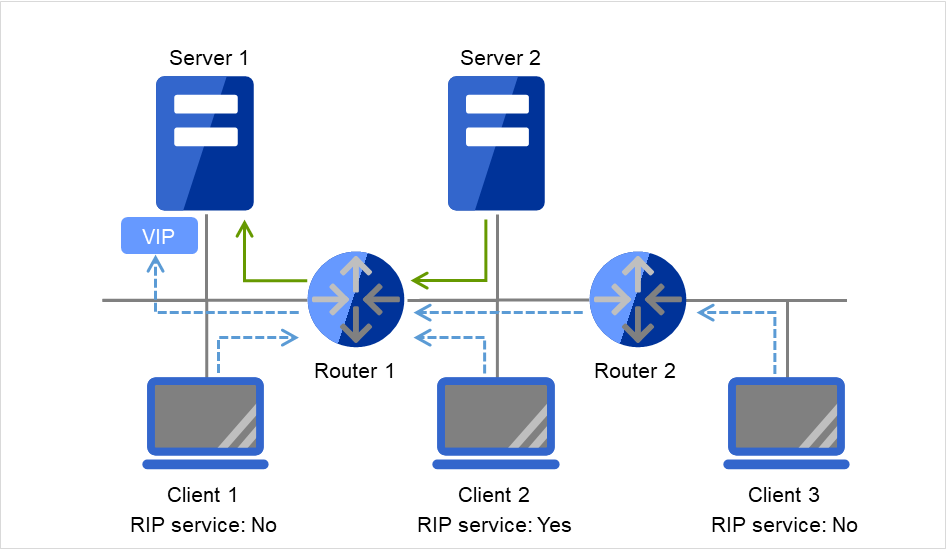
Fig. 3.104 Configuration with a virtual IP address (1)
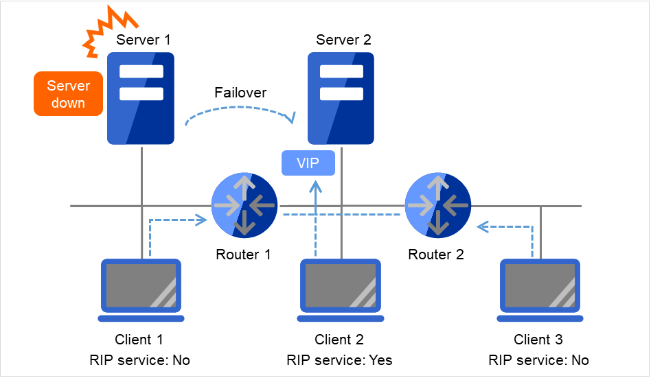
Fig. 3.105 Configuration with a virtual IP address (2)
- Note on setting servers (1)Each cluster server on the same LAN requires being able to change the path by receiving RIP packets, or to resolve path information on the virtual IP address by accessing a router.
- Note on setting servers (2)Each cluster server in a separate segment requires being able to resolve path information on the virtual IP address by accessing a router.
- Note on setting virtual IP resources (1)Specify an IP address outside the LAN to which the cluster servers belong, and free from a collision with existing IP addresses.
- Note on setting routers (1)Each router requires being able to perform dynamic routing by interpreting RIP packets, or to resolve path information on the virtual IP address as static path information.
- Note on setting virtual IP resources (2)Be sure to specify a sender's IP address for each of the servers in order for RIP packets to be correctly sent.
- Note on setting routers (2)Set the flush timer of each router at a value within the heartbeat timeout value.
- Note on setting clients (1)Each client on the same LAN requires being able to change the path by receiving RIP packets, or to resolve path information on the virtual IP address by accessing a router.
- Note on setting clients (2)Each client in a separate segment requires being able to resolve path information on the virtual IP address by accessing a router.
3.16.3. Determining virtual IP address
An IP address used as a virtual IP address should satisfy the following conditions:
The IP address should not be within the network address of the LAN to which the cluster belongs.
The IP address should not conflict with existing network addresses.
Select one of the following allocation methods to meet the requirements above:
Obtain a new network IP address for virtual IP address and allocate virtual IP address.
Determine a network IP address from private IP address space and allocate virtual IP address. The following procedures are given as an example.
Select one network address from 192.168.0 to 192.168.255 for virtual IP address.
Allocate up to 64 host IP addresses for virtual IP address from the network address you have selected. (For example, select the network address 192.168.10 and allocate two host IP addresses: 192.168.10.1 and 192.168.10.254)
Specify 255.255.255.0 to net mask of the virtual IP address.
Private IP addresses are addresses for a closed network and they cannot be accessed using virtual IP address from outside of the network through internet providers.
Do not disclose path information of private IP addresses outside the organization.
Adjust the private IP addresses to avoid conflict with other address.
3.16.4. Controlling path
To access to a virtual IP address from a remote LAN, path information of the virtual IP address must be effective to all routers on the path from the remote LAN to the LAN for cluster server.
To be specific, the following condition must be satisfied:
Routers on the cluster servers LAN interpret host RIP.
Routers on the path from a cluster server to the remote server have the dynamic routing settings or information on the virtual IP address routes has configured as static routing settings.
3.16.5. Requirement to use virtual IP address
Environments where virtual IP address can be used
Virtual IP addresses can be accessed from the machines listed below. Virtual IP address mechanism functions properly even in a LAN where switching hubs are used.
However, when a server goes down, TCP/IP that has been connected will be disconnected.
When using virtual IP addresses with a switching HUB that cannot be configured to create a host routing table by receiving host RIP, you need to reserve one new network address and configure virtual IP addresses so that the IP address of each server belongs to a different network address.
Cluster servers that belong to the same LAN that the server the virtual IP activates belongs to
Virtual IP addresses can be used if the following conditions are satisfied:
Machines that can change the path by receiving RIP packets.
Machines that can resolve the path information of a virtual IP address by accessing a router.
Cluster servers that belong to a different LAN that the server the virtual IP activates belongs to
Virtual IP addresses can be used if the following condition is satisfied:
Machines that can resolve path information of the virtual IP address by accessing a router.
Clients that belong to the same LAN that cluster servers belong to
Virtual IP addresses can be used if the following conditions are satisfied:
Machines that can change the path by receiving RIP packets.
Machines that can resolve the path information of a virtual IP address by accessing a router.
Clients on the remote LAN
Virtual IP addresses can be used if the following condition is satisfied:
Machines that can resolve path information of the virtual IP address by accessing a router.
3.16.6. Notes on virtual IP resources
Virtual IP addresses do not support NetBIOS protocol.
Even if you map a virtual IP address to a host name using LMHOSTS, it cannot be used for accessing and user authentication for Windows browsing, networks, and printer resources.
Use a virtual computer name to automatically switch the connection destination with the NetBIOS protocol.
The following rule applies to virtual IP addresses.
The number of a virtual IP resource to be registered on one cluster system is up to 64.
To use a virtual IP resource, the names of a cluster, server and group need to be set according to the naming rules of Ver8.0 or earlier.
Adjust the value of the flush timer of the router within the value for heartbeat timeout. For the heartbeat timeout, see "Timeout tab" in "Cluster properties" in "2. Parameter details" in this guide.
It is necessary to add the Routing and Remote Access service to each cluster server to enable the LAN routing. This is not required when the interconnect LAN with the highest priority is common to public LAN.
When an IPv6 address is used as a virtual IP address, it is necessary to specify public LAN as the interconnect with the highest priority.
If the routing protocol is set to "RIPver2," the subnet mask for transmitted RIP packets is "255.255.255.255."
3.16.7. Details tab

IP Address (Within 45 bytes)
Enter the virtual IP address to use.
Net Mask (Within 45 bytes)
Specify the net mask of the virtual IP address to use. It is not necessary to specify it when the IPv6 address is specified as a virtual IP address.
Destination IP Address (Within 45 bytes)
Enter the destination IP address of RIP packets. The broadcast address of the LAN where the cluster server belongs is specified for IPv4 and the IPv6 address of the router of the LAN where the cluster server belongs is specified for IPv6.
Source IP Address (Within 45 bytes)
Enter the IP address to bind for sending RIP packets. Specify the actual IP address activated on NIC which activates the virtual IP address.
When using an IPv6 address, specify a link local address as the source IP address.
Note
The source IP address should be set on a server basis, and set the actual IP address of each server. Virtual IP resources do not operate properly if a source address is invalid.
In the [common] tab, described the Source IP Address of any of the server, the other server, please to perform the individual settings.
Send Interval (1 to 30)
Specify the send interval of RIP packets.
Use Routing Protocol
Specify the RIP version to use. For IPv4 environment, select RIPver1 or RIPver2. For IPv6 environment, select RIPngver1 or RIPngver2 or RIPngver3. You can select one or more routing protocol.
Tuning
Use this button to display the Virtual IP Resource Tuning Properties dialog box. You can make advanced settings for the virtual IP resource.
Virtual IP Resource Tuning Properties
Parameter tab
Detailed setting for parameter is displayed.
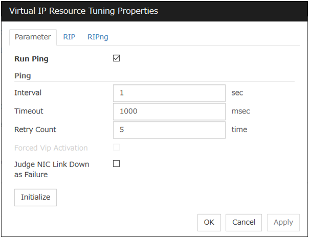
Run ping
Use this button to configure whether or not to check if there is any overlapped IP address by the ping command before activating the virtual IP resource.
ping
In this box, make detailed settings of the ping command used to check for any overlapped IP address before activating the virtual IP resource.
Judge NIC Link Down as Failure
Specify whether to check for an NIC Link Down before the floating IP resource is activated.
Initialize
Clicking Initialize sets the values of all the items to the defaults.
RIP tab
Detailed settings on RIP of virtual IP resource are displayed.

Next Hop IP Address
Enter the next hop address (address of the next router). Next hop IP address can be omitted. It can be specified for RIPver2 only. You cannot specify a netmask or prefix.
Metric (1 to 15)
Enter a metric value of RIP. A metric is a hop count to reach the destination address.
Port
On Port Number, a list of communication ports used for sending RIP is displayed.
Add
Add a port number used for sending RIP. Click this button to display the dialog box to enter a port number.
Port Number
Enter a port number to be used for sending RIP, and click OK.

Remove
Click Remove to delete the selected port on the Port Number.
Edit
A dialog box to enter a port number is displayed. The port selected in the Port Number is displayed. Edit it and click OK.
Initialize
Clicking Initialize sets the values of all the items to the defaults.
RIPng tab
Detailed settings of RIPng of virtual IP resource are displayed.
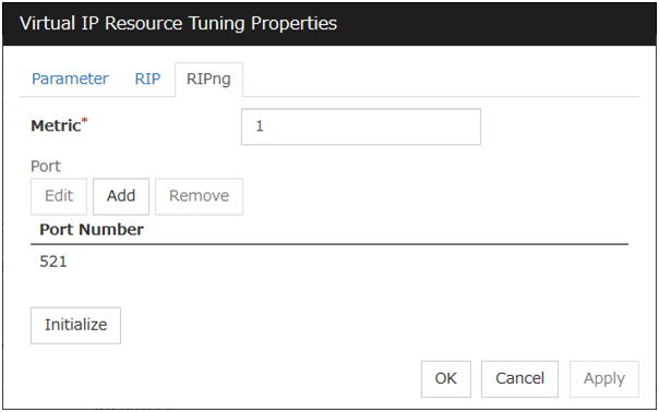
Metric (1 to 15)
Enter a metric value of RIPng. A metric is a hop count of RIPng to reach the destination address.
Port
On Port Number, a list of ports used for sending RIPng is displayed.
Initialize
Clicking Initialize sets the values of all the items to the defaults.
Add
Add a port number used for sending RIPng. Click this button to display the dialog box to enter a port number.
Port Number
Enter a port number to be used for sending RIPng, and click OK.

Remove
Click Remove to delete the selected port on the Port Number.
Edit
A dialog box to enter a port number is displayed. The port selected in the Port Number is displayed. Edit it and click OK
3.17. Understanding CIFS resources
3.17.1. Dependencies of CIFS resources
By default, CIFS resources depend on the following group resources type:
Group resource type |
|---|
Disk resource |
Mirror disk resource |
Hybrid disk resource |
3.17.2. CIFS resources
CIFS resources control publicizing and removal of shared folders. By using CIFS resources, the folders on shared disks and mirror disks are publicized as a shared file.
There are two ways of publicizing as follows:
Specify shared configuration individually
Specify shared folder configuration in advance in configuration items of CIFS resources, and then publicize shared folder with the configuration specified at resource activation. You need to create CIFS resource per shared folder to be publicized.
Auto-save shared configuration of drive
When a specified folder on shared disk/mirror disk is shared and publicized, acquire the shared configuration and save it in the configuration file of shared disk/mirror disk. The shared configuration is once released when shared disk/mirror disk is deactivated, but the shared folder is publicized again with the saved configuration.This section describes the operation when you have checked the [Auto-save shared configuration of drive].CIFS resources will automatically get the information of the shared folder on the drive, and then save it to the [Shared Configuration File]. Because it does not exist shared settings file during the initial start-up of CIFS resources, it scans all of the shared folder information on the drive, and then save it to the [Shared Configuration File].Then you can update the shared settings file from the CIFS resources each time the set of shared folder is changed.When CIFS resources becomes deactivation I will remove all share.However, since the rest is shared information in the [Shared Configuration File], and then automatically recover the shared information at the time of activity.The following table shows the advantage and disadvantage of the two methods.
Advantage
Disadvantage
Specify shared configuration individually
Inconsistency does not occur in the shared configuration.
When the shared configuration is changed, it is necessary to change the CIFS resource.
Auto-save shared configuration of drive
Changes made for the shared configuration are automatically saved.
When the shared configuration file is corrupted, inconsistency occurs in the shared information.
3.17.3. Notes on CIFS resources
When files on the shared disks or the mirror disks are publicized, the sharing settings, which are configured by right-click, will be cleared by deactivation of disk resource or mirror disk resource, which will result in no inheritance to another server at a failover. In this case, publicize and delete the shared folders by using the ARMNSADD and ARMNSDEL commands from scrip resource, or use CIFS resources.
When shared configuration of drive is automatically saved, shared configuration file configured as the saving destination is created as a hidden file. For the back up when the shared configuration file is corrupted, a file with ".bak" at the end of the specified file name is created in the same folder. Ensure not to use the same file name with the currently existing file.
A folder that the shared configuration file is to be created must have access permission to create/update a file for the local system account (SYSTEM). Without proper access permission, creation/updating of the shared configuration file fails. If both the shared configuration file and the backup file are deleted mistakenly, configuration data may be lost. It is recommended that these files should not be deleted by other account.
- If any of the conditions mentioned below arises when publicizing and removing of the shared folders on the disk (eg. shared disk, mirror disk) managed by EXPRESSCLUSTER is controlled with CIFS resources, the activation of CIFS resources fails. Perform troubleshooting procedure 1 or 2. Troubleshooting procedure 1 is recommended.<Conditions>
The failback of the CIFS resources is executed after the server is restarted for a reason other than cluster shutdown and reboot.
CIFS resources are activated for the first time after a deactivation error.
<Troubleshooting procedure 1>Select the When folder is shared not as activity failure check box.<Troubleshooting procedure 2>It is necessary to delete the shared name by using a script resource before activating CIFS resources. Add a script resource and change the settings, as follows.Add a script resource, and open Properties. In the Dependency tab, clear Follow the default dependence, and add the corresponding disk resource to Dependent Resources.
- Open the Details tab of the script resource added in 1, and add the following lines of code (*) to start.bat.:NORMALnet share <CIFS_resource_controlled_shared_name> /delete (Add)(Omitted):FAILOVERnet share <CIFS_resource_controlled_shared_name> /delete (Add)To use Auto-save shared configuration of drive for CIFS resources, it is necessary to add all the shared names controlled with CIFS resources.
Open Properties of CIFS resources. In the Dependency tab, clear Follow the default dependence, and add the corresponding disk resource and the script resource added in 1 to Dependent Resources.
Sharing access Please set a reference that can be user/groups from all cluster nodes. It does not set NTFS Permissions in CIFS resource
When migrating the Active Directory server, if you configure the accounts of the migration source and destination server domains to share a shared folder with the SID history function enabled, the share setting for the accounts of the source server cannot be maintained.
If the access permissions applied to the shared folder are either of the following, activating a CIFS resource fails. Apply the proper access permissions.
Among the SYSTEM access permissions, the Read permission is denied.
Among the SYSTEM access permissions, the List of Folder Contents permission is denied.
When When folder is shared not as activity failure is enabled (selected), activating the CIFS resource fails if a user saved in the Shared Configuration File is deleted. To delete a user who is set in Permissions for the shared folder, perform either of the following:
Disable (clear) When folder is shared not as activity failure.
To delete a use who is set in Permissions for the shared folder, also delete the corresponding group from Advanced Sharing > Permissions on the Sharing tab of the properties of the shared folder on the drive set to the CIFS resource.
If the Shared Configuration File is damaged, recover it by performing either of the following:
Among the SYSTEM access permissions, the Read permission is denied. Stop the CIFS resource and replace the damaged file with the backed up Shared Configuration File. Then, start the CIFS resource. This method is effective when there are many folders or there are many sharing settings required to change.
Stop the CIFS resource and delete the damaged Shared Configuration File. Then, start the CIFS resource and make the sharing settings again from Explorer.
If a failover occurred, the shared folder disappears temporarily. This might disable to browse the file open before the failover occurrence or to browse files from Explorer. Therefore, it is recommended to use the shared folder offline as follows:
When Execute the automatic saving of shared configuration of drive is enabled (selected), select All files and programs that users open from the share are automatically available offline for the Cache settings of the shared folder.
When Execute the automatic saving of shared configuration of drive is disabled (not selected), select Automatic Caching on the Cache tab of the CIFS resource tuning properties.
3.17.4. Details tab

Execute the automatic saving of shared configuration of drive
Configure whether to save shared configuration of drive automatically. Check this when you want to set the auto-saving.
Target Drive
Specify the drive letter of the target disk when you want to execute auto saving of shared configuration of drive.
Shared Configuration File (Within 225 bytes)
Specify the file that saves shared configuration of drive with full path. You need to specify a path of shard disk/mirror disk/hybrid disk within the same group.
This is the file that CIFS resource creates. There is no need for you to prepare before CIFS resource activation.
Errors in restoring file share setting are treated as activity failure
When this option is selected: Activating CIFS resources fails in cases where users saved in shared configuration file does not exist or user information cannot be obtained from domain environment. When the shared folder configuration is changed, if no user is set in Permissions for the shared folder or if user information cannot be obtained from the domain environment, a warning message appears.When this option is not selected (default): Activating CIFS resources is successful in above cases. The file sharing access permission is not granted to a user whose information could not be acquired. The warning message does not appear.The following configurations are executed when specifying shared configuration individually.
Shared name (Within 79 bytes)
Specify the name of the shared folder, which is publicized by using CIFS resource. The following can not be used.
Folder (Within 255 bytes)
Specify the full path to the shared folder, which is publicized by CIFS resources.
Comment (Within 255 bytes)
Specify the comment of the shared folder, which is publicized by using CIFS resource.
When folder is shared not as activity failure
When this option is not selected: The activation of CIFS resources fails when folders are already shared. In Windows Server 2012 or later, this condition always arises because of the change in the OS specifications. It is therefore recommended to check this option.When this option is selected (default): The activation of CIFS resources succeeds in the above case. The warning message is not output.
Tuning
Display CIFS resource tuning properties dialog box. You can change the settings of the detail information of the CIFS resource.
CIFS resource tuning properties
Cache tab
Display the details of cache
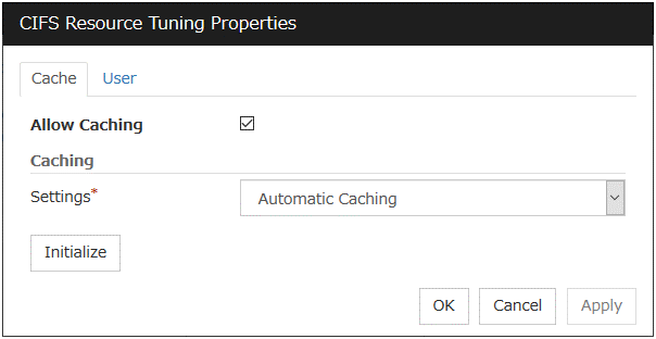
Allow Caching
Set to enable the caching of shared folders. By enabling this function, the files in the shared folders can be referenced in the offline status when specifying shared configuration individually, and those files can still be referenced after a failover. This function is not used when Auto-save shared configuration of drive method is selected.
Settings
Select the caching settings if you choose to allow caching.
Choose one of the following settings. Manual Caching (Enable BranchCache) is not supported.
Initialize
Click Initialize to initialize all the items to the default value.
User tab
Display the detailed settings of restriction of the number of users and permission of access.
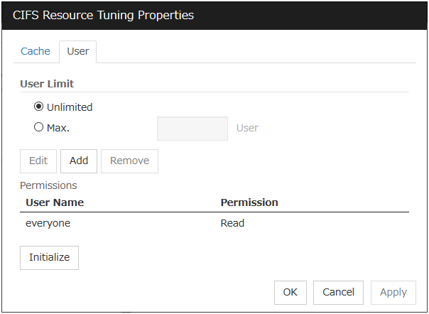
User Limit (1 to 9999)
Set the maximum number of users who can access the shared folder at a time.
Add
Add the settings of access permission for user account or user group to Access Permission. When you click this button, the Enter user dialog box is displayed. Specify the user name and the permission.
Remove
Delete the access permission selected in Permissions.
Edit
Modify the access permission specified in Permissions. The Enter user dialog box is displayed. The specified access permission displayed in the Enter user allows you to modify permission.
Initialize
Click Initialize to initialize all the items to the default values.

User Name (Within 255 bytes)
Enter the Window user name or a group name. When using a domain account, enter in the format of "Domain_name\User_name". No two-byte characters can be registered for User Name. A name containing a one-byte space can be registered. (Example: Domain Admins). If you want to use the double-byte characters in the Windows user name or group name, please check the Auto-save shared configuration of drive.
Permission
Select one of following settings for access permission of the entered user/group.
Full control
Change
Read
None
When None is selected, access is denied.
3.18. Understanding NAS resources
3.18.1. Dependencies of NAS resources
By default, NAS resources depend on the following group resources types:
Group resource type |
|---|
Floating IP resource |
Virtual IP resource |
AWS elastic ip resource |
AWS virtual ip resource |
AWS DNS resource |
Azure probe port resource |
Azure DNS resource |
3.18.2. NAS resources
NAS resources control mounts / unmounts of a network drive. By storing data required for business operation on the network drive mounted by NAS resources, the data is taken over to the other servers in the case of failover or transfer of fail groups.
3.18.3. Notes on NAS resources
NAS resources mount a network drive by local system account. Because applications and scripts activated by the application resources or script resources are executed in the local system unless otherwise specified, they can access this network drive. However applications with no permission to access the shared folder mounted as the network drive cannot access the network drive mounted by NAS resources.
When multiple NAS resources mount the shared folders on the same file server, the same name should be configured as the account to access the file server.
For the applications (databases) for which orders for the orders to disks and completion of writing should be assured the network drive may not be used as storage for data files.
The network drive mounted by NAS resource is displayed as Disconnected Network Drive in My computer on explorer. The connection account information configured by NAS resources is not taken over to the logon session except local system account. When the login account has no right to the target shared folders, you cannot access this network drive from explorer unless you explicitly specify the connecting account to the server that has the shared folders.
3.18.4. Details tab

Drive
Specify the drive letter of the network to be mounted by NAS resource.
Folder (Within 1023 bytes)
Specify the shared folder mounted by NAS resource in the UNC format.
User Name (Within 95 bytes)
Specify the user name of the account required to mount shared folders by NAS resources. No two-byte characters can be registered for User Name. A name containing a one-byte space can be registered. (Example: Domain Admins).
Enter it as a file_server_name\user_name or a domain_name\user_name. (Example: SERVER1\user)
Password (Within 255 bytes)
Specify the account password required to mount shared folders by NAS resource.
Tuning
Display the NAS Resource Tuning Properties dialog to set the details of NAS resource.
NAS resource tuning properties
Disconnect
Display the details about mounting of network drive.

Retry Threshold (0 to 999)
Specify the number of times to retry when failed to unmount.
Retry Interval (0 to 999)
Specify the retry intervals when failed to unmount.
Initialize
Click Initialize to initialize all the items to the default values.
3.19. Understanding hybrid disk resources
3.19.1. Dependencies of hybrid disk resources
By default, hybrid disk resources do not depend on any group resource type.
3.19.2. Hybrid disk
A hybrid disk resource is a resource in which disk resource and mirror disk resource are combined. When you use a disk resource, a failover group can perform failover only to the cluster server connected to the same shared disk. On the other hand, in hybrid disk, by mirroring the data in the shared disk, failover can be performed to a server which is not connected to the shared disk. This enables configuring a remote cluster as in the following figure, where failover is performed in the active site upon normal failure, while failover can be performed to the stand-by site when a disaster occurs.
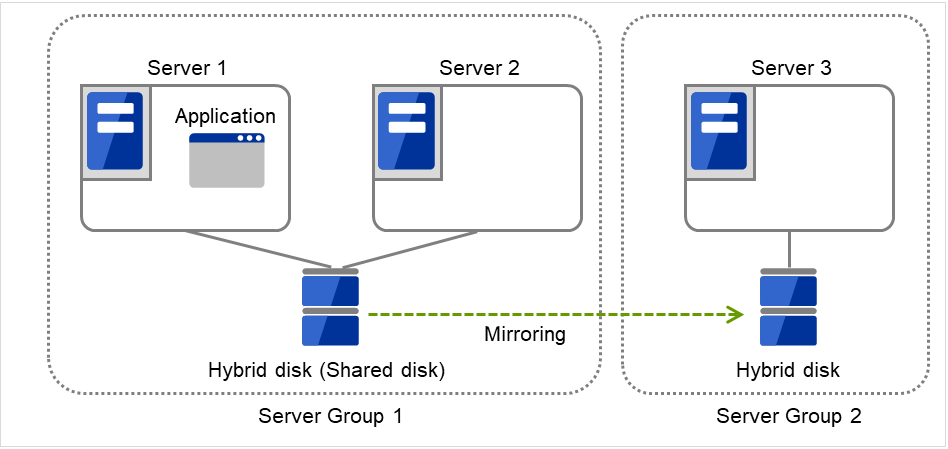
Fig. 3.106 Hybrid configuration (1): in a normal case
When Server 1 crashes, the application is failed over to Server 2.
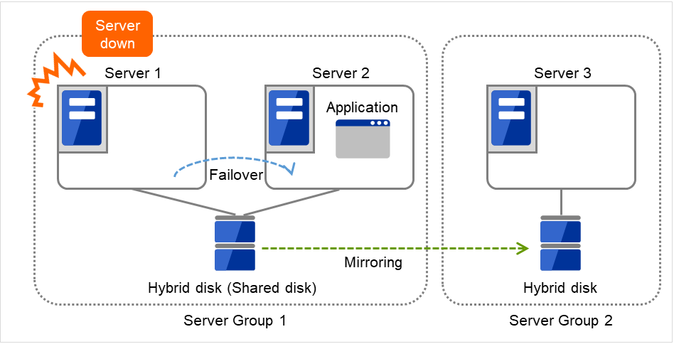
Fig. 3.107 Hybrid configuration (2): Server 1 crashes
When Server 2 crashes, the application is failed over to Server 3.
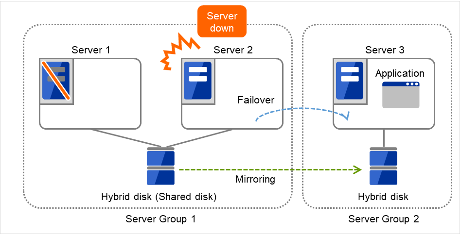
Fig. 3.108 Hybrid configuration (3): Server 2 crashes
In hybrid disk, a group of servers that is connected to the shared disk is referred to as a server group. Disk mirroring is performed between two server groups. A server which does not use the shared disk is a server group in which there is only one server.
Like mirror disk resources, mirroring takes place in each partition, where RAW partition (cluster partition) to record management information is required as well as data partition which is the mirroring target. It is necessary that each server using hybrid disk resource has a license for EXPRESSCLUSTER X Replicator DR 4.3 for Windows.
3.19.3. Notes on hybrid disk resources
- Data partition sizeThe sizes of data partitions to be mirrored need to be exactly the same by byte.If the type or geometry of the disks differs, you may fail to configure the same size for partitions. If this happens, check the precise size of data partitions of the servers by the clpvolsz command before configuring hybrid disk resource. If the sizes are not consistent, run the clpvolsz command again to contract the larger partition.For details on the clpvolsz command, see "Tuning partition size (clpvolsz command)" in "8. EXPRESSCLUSTER command reference" in this guide.There is no limit for data partition size.
- Time required for data partition copyingWhen a file is copied at initial configuration or disk replacement, the required amount of time increases in proportion to the size of the volume use area. If the volume use area cannot be specified, the required amount of time increases in proportion to the data partition size because the entire area of the volume is copied.
- Cluster partition sizeReserve at least 1024MB. In some disk geometry it may be 1024MB or larger, which is not a problem.
- Partition drive letterSpecify the same drive letters in each server for data partition and cluster partition.Do not change the drive letter until deleting resources after configuring hybrid disk resources. If a drive letter has been changed, restore the drive letter when hybrid disk resource is started. When the original drive letter is used by other partition, starting mirror disk resource fails.
- Partition allocationWhen a data partition on the shared disk is mirrored, the data partition and the cluster partition need to be allocated on the same shared disk (they do not have to be allocated on the same logical disk).Allocate the data partition and the cluster partition on a basic disk. Dynamic disk is not supported.When making data partitions as logical partitions on the extended partition, make sure the data partitions are logical partition on both servers. The actual size may be slightly different even the same size is specified on both basic partition and logical partition.
- Partition formatFormat a data partition by NTFS. FAT/FAT32 is not supported.Do not construct a file system in a cluster partition. Do not format it.
- Access control of a data partitionThe data partition to be mirrored by a hybrid disk resource can be accessed only from the active server where a hybrid disk resource is activated. Access from other servers is restricted by EXPRESSCLUSTER.Access to the cluster partition is also restricted by EXPRESSCLUSTER.
- Partition deletionWhen you delete a data partition or cluster partition on the hybrid disk resource, delete the hybrid disk resource in Cluster WebUI in advance.
- Server group settingsIn a failover group having hybrid disk resource, it is necessary to register two server groups which are mirrored by the hybrid disk resource in the Server Groups tab of Group Properties. Configure the settings for these server groups in Server Groups in the config mode of Cluster WebUI.
- Changing the configuration between the mirror disk and hybrid diskTo change the configuration so that the disk mirrored using a mirror disk resource will be mirrored using a hybrid disk resource, first delete the existing mirror disk resource from the configuration data, and then upload the data. Next, add a hybrid disk resource to the configuration data, and then upload it again.
- Disk devices that configure hybrid disksFor the data partition and the cluster partition of hybrid disk resources, use disk devices with the same logical sector size on all servers. If you use devices with different logical sector sizes, they do not operate normally. They can operate even if they have different sizes for the data partition and the cluster partition.
Examples)
Combination
Logical sector size of the partition
Description
Server 1
Server 1
Server 2
Server 2
DatapartitionClusterpartitionDatapartitionClusterpartitionOK
512B
512B
512B
512B
The logical sector sizes are uniform.
OK
4KB
512B
4KB
512B
The data partitions have a uniform size of 4 KB, and the cluster partitions have a uniform size of 512 bytes.
NG
4KB
512B
512B
512B
The logical sector sizes for the data partitions are not uniform.
NG
4KB
4KB
4KB
512B
The logical sector sizes for the cluster partitions are not uniform.
- Auto Mirror Initial Construction is set not to be performedWhen you use the hybrid disk resource after disabling Auto Mirror Initial Construction on the Mirror Disk tab in the Cluster Properties, change the icon color of the source server group to green by using Mirror Disks before starting hybrid disk resources for the first time.
3.19.4. Details tab

Hybrid Disk No.
Select a disk number to be allocated to a hybrid disk resource. This number must be different from the ones for other hybrid disk resources and mirror disk resources.
Data Partition Drive Letter (Within 1023 bytes)
Specify the drive letter (A to Z) for the data partition.
Cluster Partition Drive Letter (Within 1023 bytes)
Specify the drive letter (A to Z) for the cluster partition. Multiple hybrid disks can use the same cluster partition, but it cannot be the cluster partition of the mirror disk resource.
Cluster Partition Offset Index
Select an index number for the area used in the cluster partition. When using the multiple hybrid disks, assign different numbers for hybrid disk so that the areas to be used in the cluster partition do not overlap.
Select
Select the communication path for the data mirroring communication (mirror disk connect). Click Select to display the Selection of Mirror Disk Connect dialog box.
For mirror disk connect settings, see "Interconnect tab" in "Cluster properties" in "2. Parameter details" in this guide.
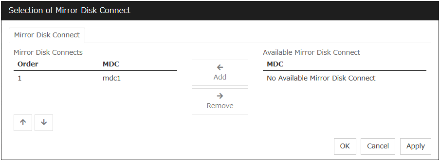
Server groups
Information on each member server of the two server groups selected in the Server Groups tab in Properties of failover groups is displayed.
Clicking Obtain information on the Cluster WebUI enables you to get GUID information for the data and cluster partitions of each server.
Tuning
The Hybrid Disk Resource Tuning Properties dialog box is displayed. You can configure the details on hybrid disk resources.
Hybrid Disk Resource Tuning Properties
Mirror tab
Detailed settings on mirror are displayed.
Parameters on this configuration window are the same as those of mirror disk resources.
For the meaning and setting method of each parameter, see " Understanding mirror disk resources ".
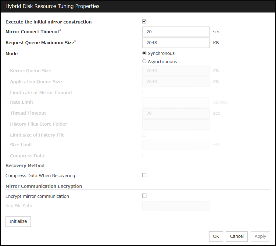
3.19.5. Notes on operating hybrid disk resources
If mirror data was synchronized on both server groups when the cluster was shut down, use one of the two orders noted below to start the servers.
Simultaneously start servers belonging to both server groups at least one at a time
Start the first server (which belongs to server group 1), and then start the second server (which belongs to server group 2) after the first server has started
Do not consecutively start and shutdown both servers 6 .The servers communicate with each other to determine whether the mirror data stored in each server group is up to date. Consecutively starting and shutting down both servers prevents the servers from properly determining whether mirror data is up to date and hybrid disk resources will fail to start the next time both server groups are started.
- 6
In other words, do not start and shut down the first server, and then start and shut down the second server.
3.20. Understanding VM resources
3.20.1. Dependencies of VM resources
By default, this function depends on the following group resource type:
Group resource type |
|---|
Disk resource |
Mirror disk resource |
Hybrid disk resource |
NAS resource |
3.20.2. VM resources
VM resources control virtual machines (guest OSs) from the host OS in the virtualization infrastructure.
VM resources start, stop or migrate virtual machines.
3.20.3. Notes on VM resources
VM resources are effective when EXPRESSCLUSTER is installed on host OS of virtual infrastructure (Hyper-V).
A VM resource can be registered with a group for which the group type is virtual machine.
Only one VM resource can be registered per group.
If VM resources are stopped, the VM is deleted from Hyper-V manager.
3.20.4. Details tab
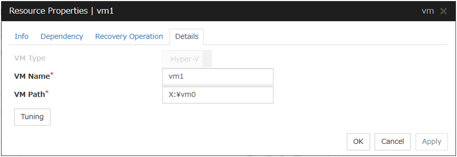
VM Type
Specify the virtualization infrastructure in which the virtual machine is set up. In this version, Hyper-V is the only option for this.
VM Name
Enter the virtual machine name displayed in the Hyper-V Manager.
VM Path
Enter the path of the virtual machine configuration file.
Tuning
This displays the Virtual Machine Resource Tuning Properties dialog box. Specify detailed settings for the VM resource.
VM Resource Tuning Properties
Parameter tab
Detailed setting for parameter is displayed.

Request Timeout
Specify how long the system waits for completion of a request such as to start or stop a virtual machineIf the request is not completed within this time, a timeout occurs and resource activation or deactivation fails.
Virtual Machine Start Waiting Time
Specify the wait time to wait for the startup completion of the guest OS on the virtual machine and the application after the request to the virtual machine to start up completes and the status of the virtual machine becomes running at the resource activation.
Virtual Machine Stop Waiting Time
Specify the wait time for the shutdown of the guest OS on the virtual machine at the resource deactivation.
Initialize
Clicking Initialize sets the values of all the items to the defaults.
3.21. Understanding AWS elastic ip resources
3.21.1. Dependencies of AWS elastic ip resources
By default, this function does not depend on any group resource type.
3.21.2. AWS elastic ip resource
By using this resource, an HA cluster can be configured with EXPRESSCLUSTER using the Amazon Virtual Private Cloud (referred to as the VPC) in the Amazon Web Services (referred to as AWS) environment.
This makes it possible to perform more important business operations in the same environment, increasing the number of choices for the system configuration in the AWS environment. AWS is configured robustly in multiple Availability Zones (referred to as AZs) in each area (region), enabling the user to select an AZ according to his or her needs. EXPRESSCLUSTER enables an HA cluster among multiple AZs (referred to as multi-AZ), achieving high availability of business operations.
Two types of HA clusters with the data mirror method are assumed, "HA cluster with VIP control" and "HA cluster with EIP control". This section describes AWS elastic ip resources that are used for "HA cluster with EIP control".
An AWS Elastic IP resource, an AWS Virtual IP resource, and an AWS DNS resource can be used together.
HA cluster with EIP control
This is used to place instances on public subnets (release business operations inside the VPC).A configuration such as the following is assumed: Instances to be clustered are placed on public subnets in each AZ, and each instance can access the Internet via the Internet gateway.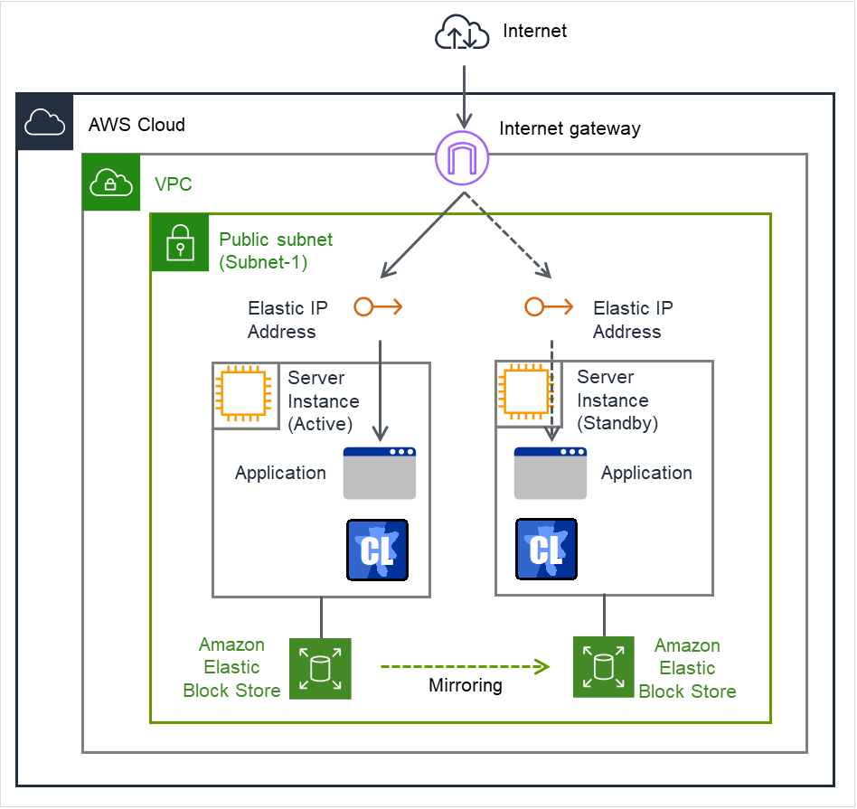
Fig. 3.109 Configuration with an AWS Elastic IP resource
3.21.3. Notes on AWS elastic ip resources
3.21.4. Applying environment variables to AWS CLI run from the AWS elastic ip resource
Specify environment variables in the environment variable configuration file to apply environment variables to the AWS CLI run from the AWS Elastic ip resource, AWS virtual ip resource, AWS DNS resource, AWS Elastic ip monitor resource, AWS virtual ip monitor resource, AWS DNS monitor resource and AWS AZ monitor resource.
This feature is useful when using a proxy server in an AWS environment.
[ENVIRONMENT]
HTTP_PROXY = http://10.0.0.1:3128
HTTPS_PROXY = http://10.0.0.1:3128
NO_PROXY = 169.254.169.254,ec2.ap-northeast-1.amazonaws.com
The specifications of the environment variable configuration file are as follows:
Write [ENVIRONMENT] on the first line. If this is not set, the environment variables will not be set.
If the environment variable configuration file does not exist or you do not have read permission for the file, the variables are ignored. This does not cause an activation failure or a monitor error.
If the same environment variables already exists in the file, the values are overwritten.
More than one variable can be set. Set one variable on each line.
The settings are valid regardless of whether there are spaces before and after "=" or not.
The settings are invalid if there is a space or tab in front of the environment variable name or if there are tabs before and after "=".
Environment variable names are case sensitive.
If a value contains spaces, you do not have to enclose the spaces in "" (double quotation marks).
The environment variables configured with the environment variable configuration file are propagated only to the AWS CLI executed from an AWS Elastic IP resource, an AWS Virtual IP resource, an AWS DNS resource, an AWS Elastic IP monitor resource, an AWS Virtual IP monitor resource, an AWS DNS monitor resource, and an AWS AZ monitor resource. Therefore, the configured variables are not propagated to any other script (e.g. a script before final action, a script before and after activation/deactivation, and a script to be run from script resources). To execute the AWS CLI with such a script, configure necessary environment variables with the corresponding script.
3.21.5. Details tab
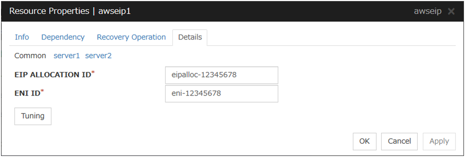
EIP ALLOCATION ID (Within 45 bytes)
For EIP control, specify the ID of the EIP to replace.
ENI ID (Within 45 bytes)
For EIP control, specify the ENI ID to which to allocate an EIP.
In the [common] tab, described the ENI ID of any of the server, the other server, please to perform the individual settings.
Tuning
Opens the AWS elastic ip resource tuning properties dialog box where the detailed settings for the AWS elastic ip resource tuning properties can be configured.
AWS Elastic IP Resource Tuning Properties
Parameter tab
Detailed setting for parameter is displayed.
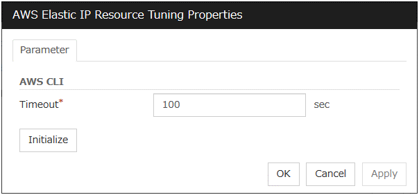
Timeout (1 to 999)
Make the setting of the timeout of AWS CLI command executed for the activation and/or deactivation of the AWS elastic ip resource and AWS elastic ip monitor resource.
3.22. Understanding AWS virtual ip resources
3.22.1. Dependencies of AWS virtual ip resources
By default, this function does not depend on any group resource type.
3.22.2. AWS virtual ip resource
By using this resource, an HA cluster can be configured with ExpressCluster using the Amazon Virtual Private Cloud (referred to as the VPC) in the Amazon Web Services (referred to as AWS) environment.
This makes it possible to perform more important business operations in the same environment, increasing the number of choices for the system configuration in the AWS environment. AWS is configured robustly in multiple Availability Zones (referred to as AZs) in each area (region), enabling the user to select an AZ according to his or her needs. ExpressCluster enables an HA cluster among multiple AZs (referred to as multi-AZ), achieving high availability of business operations.
AWS CLI command is executed for AWS virtual ip resource when it is activated to update the route table information.
Two types of HA clusters with the data mirror method are assumed, "HA cluster with VIP control" and "HA cluster with EIP control". This section describes AWS virtual ip resoruces that are used for "HA cluster with VIP control"
An AWS Elastic IP resource, an AWS Virtual IP resource, and an AWS DNS resource can be used together.
HA cluster with VIP control
This is used to place instances on private subnets (release business operations inside the VPC).A configuration such as the following is assumed: Instances to be clustered, as well as the instance group accessing the instances, are placed on private subnets in each AZ, and each instance can access the Internet via the NAT instance placed on the public subnet.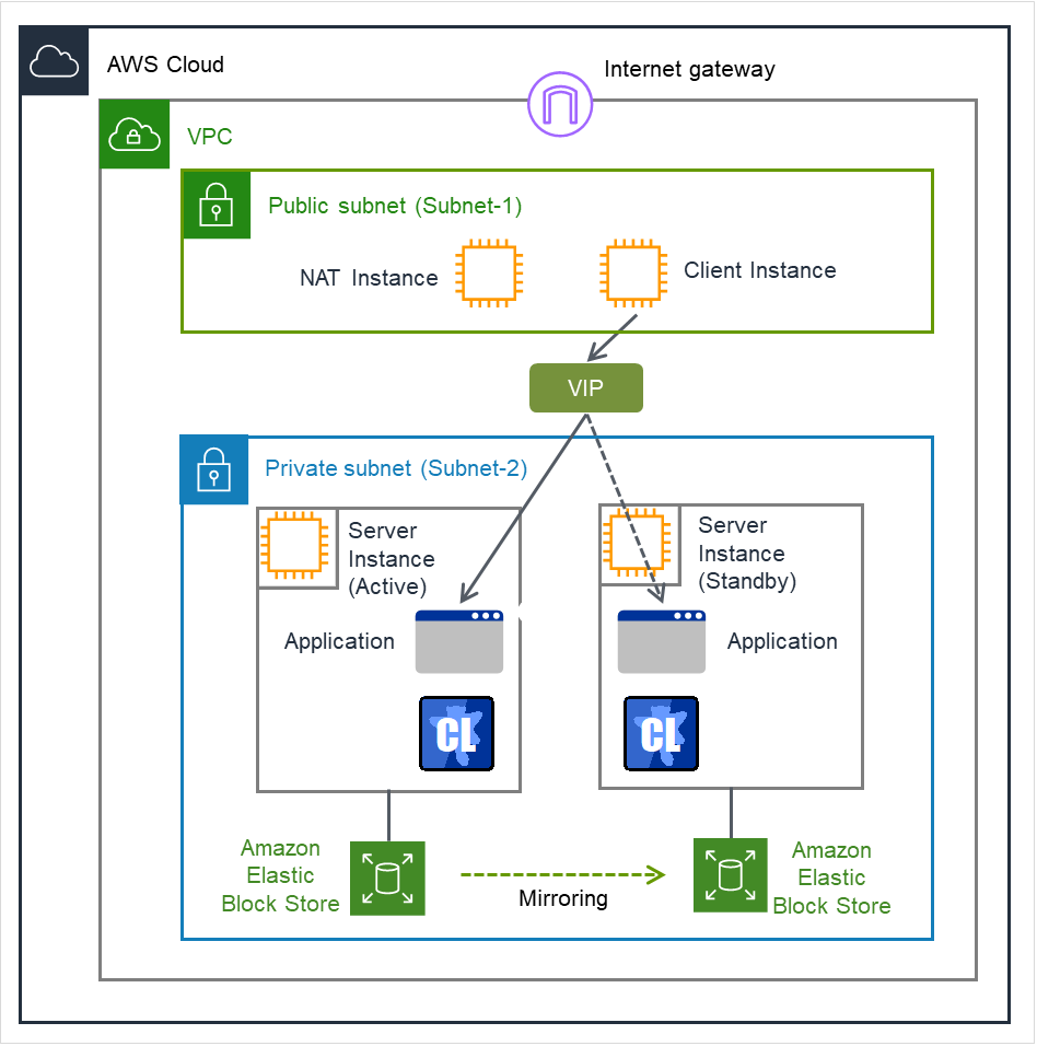
Fig. 3.110 Configuration with an AWS Virtual IP resource
3.22.3. Notes on AWS virtual ip resources
3.22.4. Applying environment variables to AWS CLI run from the AWS virtual ip resource
Specify environment variables in the environment variable configuration file to apply environment variables to the AWS CLI run from the AWS Elastic ip resource, AWS virtual ip resource, AWS DNS resource, AWS Elastic ip monitor resource, AWS virtual ip monitor resource, AWS DNS monitor resource and AWS AZ monitor resource.
This feature is useful when using a proxy server in an AWS environment.
[ENVIRONMENT]
HTTP_PROXY = http://10.0.0.1:3128
HTTPS_PROXY = http://10.0.0.1:3128
NO_PROXY = 169.254.169.254,ec2.ap-northeast-1.amazonaws.com
The specifications of the environment variable configuration file are as follows:
Write [ENVIRONMENT] on the first line. If this is not set, the environment variables will not be set.
If the environment variable configuration file does not exist or you do not have read permission for the file, the variables are ignored. This does not cause an activation failure or a monitor error.
If the same environment variables already exists in the file, the values are overwritten.
More than one variable can be set. Set one variable on each line.
The settings are valid regardless of whether there are spaces before and after "=" or not.
The settings are invalid if there is a space or tab in front of the environment variable name or if there are tabs before and after "=".
Environment variable names are case sensitive.
If a value contains spaces, you do not have to enclose the spaces in "" (double quotation marks).
The environment variables configured with the environment variable configuration file are propagated only to the AWS CLI executed from an AWS Elastic IP resource, an AWS Virtual IP resource, an AWS DNS resource, an AWS Elastic IP monitor resource, an AWS Virtual IP monitor resource, an AWS DNS monitor resource, and an AWS AZ monitor resource. Therefore, the configured variables are not propagated to any other script (e.g. a script before final action, a script before and after activation/deactivation, and a script to be run from script resources). To execute the AWS CLI with such a script, configure necessary environment variables with the corresponding script.
3.22.5. Details tab
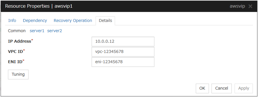
IP Address (Within 45 bytes)
For VIP control, specify a VIP address to be used: an IP address not belonging to VPC CIDR.
VPC ID (Within 45 bytes)
For VIP control, specify the VPC ID to which the server belongs. To specify an individual VPC ID to servers, enter a VPC ID of any server on the Common tab and specify a VPC ID for other servers individually.
ENI ID (Within 45 bytes)
For VIP control, specify the ENI ID of VIP routing destination. For the ENI ID to specify, Source/Dest. Check must be disabled beforehand. This must be set for each server. On the Common tab, enter the ENI ID of any server, and specify an ENI ID for the other servers individually.
Tuning
Opens the AWS virtual ip resource tuning properties dialog box where the detailed settings for the AWS virtual ip resource tuning properties can be configured.
AWS Virtual Ip Resource Tuning Properties
Parameter tab
Detailed setting for parameter is displayed.

Timeout (1 to 999)
Set the timeout of the AWS CLI command to be executed for AWS virtual ip resource activation/deactivation.
3.23. Understanding AWS DNS resources
3.23.1. Dependencies of AWS DNS resources
By default, this function does not depend on any group resource type.
3.23.2. AWS DNS resource
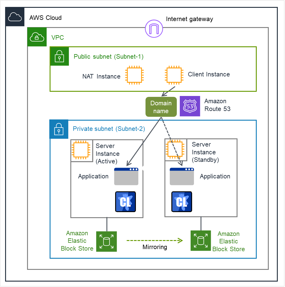
Fig. 3.111 Configuration with an AWS DNS resource
An AWS DNS resource registers an IP address corresponding to the virtual host name (DNS name) used in Amazon Web Services (hereinafter, referred to as "AWS") by executing AWS CLI at activation, and deletes it by executing AWS CLI at deactivation.
A client can access the node on which failover groups are active with the virtual host name.
By using AWS DNS resources, clients do not need to be aware of switching access destination node when a failover occurs or moving a group migration.
If using AWS DNS resources, you need to take the following preparations before establishing a cluster.
Creating Hosted Zone of Amazon Route 53
Installing AWS CLI
An AWS Elastic IP resource, an AWS Virtual IP resource, and an AWS DNS resource can be used together.
3.23.3. Notes on AWS DNS resources
In client access using a virtual host name (DNS name), if a failover group to which the AWS DNS resource is added resource is failed over, reconnection may be required.
See " Setting up AWS DNS resources" in "Notes when creating the cluster configuration data" in "Notes and Restrictions" in the "Getting Started Guide".
3.23.4. Applying environment variables to AWS CLI run from the AWS DNS resource
Specify environment variables in the environment variable configuration file to apply environment variables to the AWS CLI run from the AWS Elastic ip resource, AWS virtual ip resource, AWS DNS resource, AWS Elastic ip monitor resource, AWS virtual ip monitor resource, AWS DNS monitor resource and AWS AZ monitor resource.
This feature is useful when using a proxy server in an AWS environment.
[ENVIRONMENT]
HTTP_PROXY = http://10.0.0.1:3128
HTTPS_PROXY = http://10.0.0.1:3128
NO_PROXY = 169.254.169.254,ec2.ap-northeast-1.amazonaws.com
The specifications of the environment variable configuration file are as follows:
Write [ENVIRONMENT] on the first line. If this is not set, the environment variables will not be set.
If the environment variable configuration file does not exist or you do not have read permission for the file, the variables are ignored. This does not cause an activation failure or a monitor error.
If the same environment variables already exists in the file, the values are overwritten.
More than one variable can be set. Set one variable on each line.
The settings are valid regardless of whether there are spaces before and after "=" or not.
The settings are invalid if there is a space or tab in front of the environment variable name or if there are tabs before and after "=".
Environment variable names are case sensitive.
If a value contains spaces, you do not have to enclose the spaces in "" (double quotation marks).
The environment variables configured with the environment variable configuration file are propagated only to the AWS CLI executed from an AWS Elastic IP resource, an AWS Virtual IP resource, an AWS DNS resource, an AWS Elastic IP monitor resource, an AWS Virtual IP monitor resource, an AWS DNS monitor resource, and an AWS AZ monitor resource. Therefore, the configured variables are not propagated to any other script (e.g. a script before final action, a script before and after activation/deactivation, and a script to be run from script resources). To execute the AWS CLI with such a script, configure necessary environment variables with the corresponding script.
3.23.5. Details tab
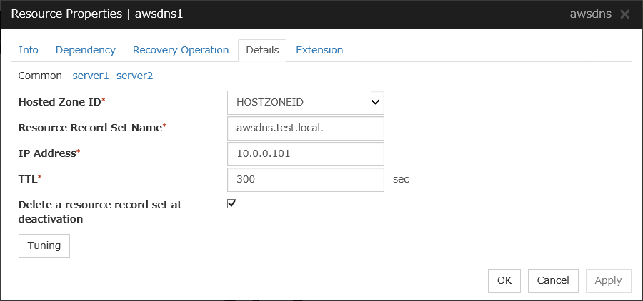
Host Zone ID (Within 255 bytes)
Specify a Hosted Zone ID of Amazon Route 53.
Resource Record Set Name (Within 255 bytes)
Specify the name of DNS A record. Put a dot (.) at the end of the name. When an escape character is included in Resource Record Set Name, a monitor error occurs. Set Resource Record Set Name with no escape character. Specify the value of Resource Record Set Name in lowercase letters.
IP Address (Within 39 bytes)
Specify the IP address corresponding to the virtual host name (DNS name) (IPv4). For using the IP address of each server, enter the IP address on the tab of each server. For configuring a setting for each server, enter the IP address of an arbitrary server on Common tab, and configure the individual settings for the other servers.
TTL (0 to 2147483647)
Specify the time to live (TTL) of the cache.
Delete a resource record set at deactivation
Tuning
Opens the AWS DNS Resource Tuning Properties dialog box where you can make detailed settings for the AWS DNS resource.
AWS DNS Resource Tuning Properties
Parameter tab
Detailed setting for parameter is displayed.

Timeout (1 to 999)
Make the setting of the timeout of AWS CLI command executed for the activation and/or deactivation of the AWS DNS resource.
3.24. Understanding Azure probe port resources
3.24.1. Dependencies of Azure probe port resources
By default, this function does not depend on any group resource type.
3.24.2. Azure probe port resource
Client applications can use the global IP address called a public virtual IP (VIP) address (referred to as a VIP in the remainder of this document) to access virtual machines on an availability set in the Microsoft Azure environment.
By using VIP, clients do not need to be aware of switching access destination server when a failover occurs or moving a group migration.
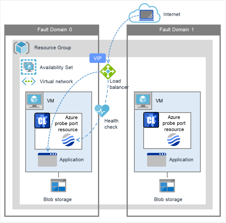
Fig. 3.112 Configuration with an Azure probe port resource
To access the cluster created on the Microsoft Azure environment, specify the end point for communicating from the outside with VIP or the end point for communicating from the outside with the DNS name. The active and standby nodes of the cluster are switched by controlling the Microsoft Azure load balancer from EXPRESSCLUSTER. For control, Health Check is used.
At activation, start the probe port control process for waiting for alive monitoring (access to the probe port) from the Microsoft Azure load balancer.
At deactivation, stop the probe port control process for waiting for alive monitoring (access to the probe port).
Azure probe port resources also support the Internal Load Balancing of Microsoft Azure. For Internal Load Balancing, the VIP is the private IP address of Azure.
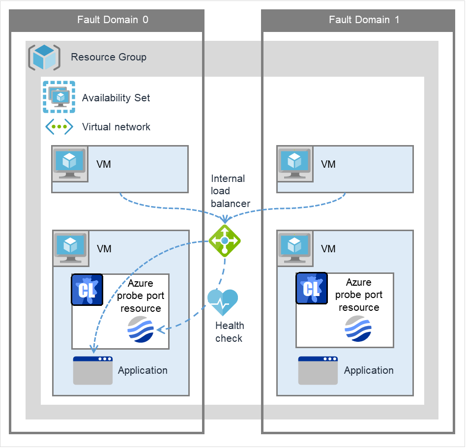
Fig. 3.113 Configuration with an Azure probe port resource (for Internal Load Balancing)
3.24.3. Notes on Azure probe port resources
If the private port and the probe port are the same, you need not add Azure probe port resources or Azure probe port monitor resources.
See " Setting up Azure probe port resources" in " Notes when creating the cluster configuration data" in "Notes and Restrictions" in the "Getting Started Guide".
3.24.4. Details tab
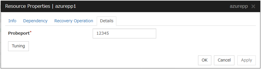
Probeport (1 to 65535)
Specify the port number used by the Azure load balancer for the alive monitoring of each server. Specify the value specified for Probe Port when creating an end point. For Probe Protocol, specify TCP.
Tuning
Display the Azure probe port Resource Tuning Properties dialog box. Specify detailed settings for the Azure probe port resources.
Azure Probe Port Resource Tuning Properties
Parameter tab
Detailed setting for parameter is displayed.
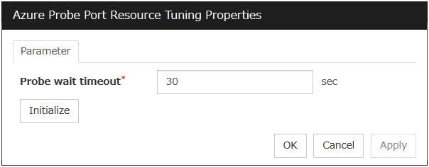
Probe wait timeout (5 to 999999999)
Specify the timeout time for waiting alive monitoring from the Azure load balancer. Check if alive monitoring is performed periodically from the Azure load balancer.
3.25. Understanding Azure DNS resources
3.25.1. Dependencies of Azure DNS resources
By default, this function does not depend on any group resource type.
3.25.2. Azure DNS resource
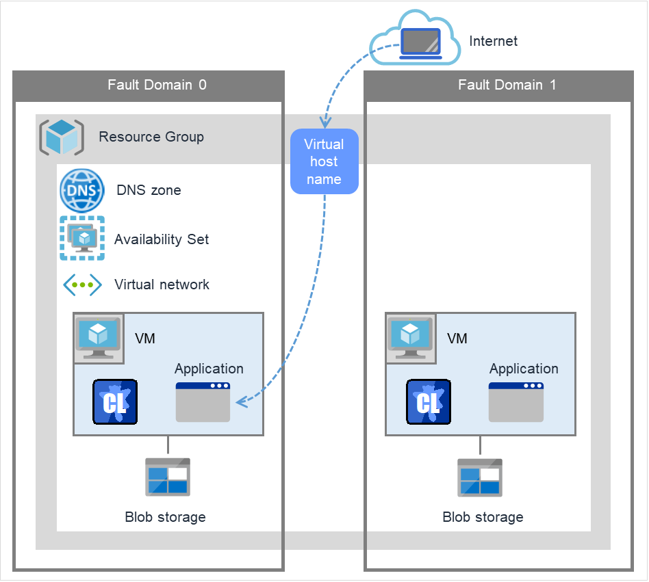
Fig. 3.114 Configuration with an Azure DNS resource
An Azure DNS resource controls an Azure DNS record set and DNS A record to obtain an IP address set from the virtual host name (DNS name).
A client can access the node on which failover groups are active with the virtual host name.
By using Azure DNS resources, clients do not need to be aware of switching access destination node on Azure DNS when a failover occurs or moving a group migration.
If using Azure DNS resources, you need to take the following preparations before establishing a cluster. For details, see " EXPRESSCLUSTER X HA Cluster Configuration Guide for Microsoft Azure (Windows)".
Creating Microsoft Azure Resource Group and DNS zone
Installing Azure CLI
3.25.3. Notes on Azure DNS resources
In client access using a virtual host name (DNS name), if a failover group to which the Azure DNS resource is added is failed over, reconnection may be required.
See "Setting up Azure DNS resources" in "Before installing EXPRESSCLUSTER" in "Notes and Restrictions" in the "Getting Started Guide".
See "Azure DNS resources" in " Notes when creating the cluster configuration data" in "Notes and Restrictions" in the "Getting Started Guide".
3.25.4. Details tab

Record Set Name (Within 253 bytes)
Specify the name of the record set in which Azure DNS A record is registered.
Zone Name (Within 253 bytes)
Specify the name of the DNS zone to which the record set of Azure DNS belongs.
IP Address (Within 39 bytes)
Specify the IP address corresponding to the virtual host name (DNS name) (IPv4). For using the IP address of each server, enter the IP address on the tab of each server. For configuring a setting for each server, enter the IP address of an arbitrary server on Common tab, and configure the individual settings for the other servers.
TTL (0 to 2147483647)
Specify the time to live (TTL) of the cache.
Resource Group Name (Within 180 bytes)
Specify the name of Microsoft Azure Resource Group to which the DNS zone belongs.
User URI (Within 2083 bytes)
Specify the user URI to log on to Microsoft Azure.
Tenant ID (Within 36 bytes)
Specify the tenant ID to log on to Microsoft Azure.
File Path of Service Principal (Within 1023 bytes)
Specify the file name of the service principal to log in to Microsoft Azure (file name of the credential. Use a full path containing a drive name to specify it.
Azure CLI File Path (Within 1023 bytes)
Specify the installation path of Azure CLI and the file name. Use a full path containing a drive name to specify them.
Delete a record set at deactivation
Tuning
Opens the Azure DNS Resource Tuning Properties dialog box where you can make detailed settings for the Azure DNS resource.
Azure DNS Resource Tuning Properties
Parameter tab
Detailed setting for parameter is displayed.
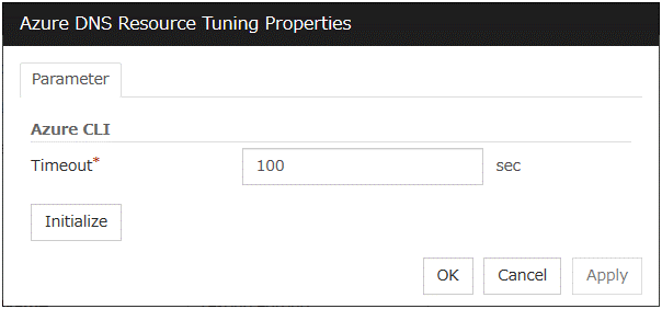
Timeout (1 to 999)
Make the setting of the timeout of the Azure CLI command executed for the activation and/or deactivation of the Azure DNS resource.
3.26. Understanding Google Cloud virtual IP resources
3.26.1. Dependencies of Google Cloud virtual IP resources
By default, this function does not depend on any group resource type.
3.26.2. What is a Google Cloud virtual IP resource?
For virtual machines in the Google Cloud Platform environment, client applications can use a virtual IP (VIP) address to connect to the node that constitutes a cluster. Using the VIP address eliminates the need for clients to be aware of switching between the virtual machines even after a failover or a group migration occurs.
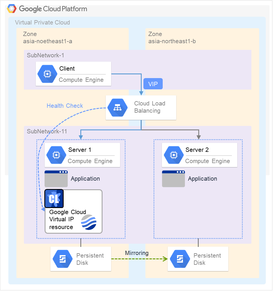
Fig. 3.115 Configuration with a Google Cloud Virtual IP resource
To access the cluster created in the Google Cloud Platform environment as in the figure above, specify the port for communicating from the outside as well as the VIP address or DNS name. The active and standby nodes of the cluster are switched by controlling the load balancer of Google Cloud Platform (Cloud Load Balancing in the figure above) from EXPRESSCLUSTER. For this control, Health Check (in the figure above) is used.
At activation, start the control process for awaiting a health check from the load balancer of Google Cloud Platform, and open the port specified in Port Number.
At deactivation, stop the control process for awaiting the health check, and close the port specified in Port Number.
Google Cloud virtual IP resources support the internal load balancing of Google Cloud Platform.
3.26.3. Notes on Google Cloud virtual IP resources
- According to the Google Cloud Platform specification, External TCP Network Load Balancer requires legacy health checks using the HTTP protocol.Google Cloud virtual IP resources only support health checks that use the TCP protocol and cannot respond to health checks from External TCP Network Load Balancer.Therefore, HA cluster using Google Cloud virtual IP resources by External TCP Network Load Balancer cannot be used. Use an Internal TCP Load Balancer.Refer to the following.Health checks overview:
If the private port is the same as the health-check port, you need not add Google Cloud virtual IP resources or Google Cloud virtual IP monitor resources.
Refer to "Getting Started Guide" -> "Notes and Restrictions" -> "Notes when creating the cluster configuration data" -> "Setting up Google Cloud Virtual IP resources".
3.26.4. Details tab
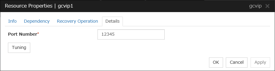
Port Number (1 to 65535)
Specify a port number to be used by the load balancer of Google Cloud Platform for the health check of each node: the value specified as the port number in configuring the load balancer for health checks. For the load balancer, specify TCP load balancing.
Tuning
Displays the Google Cloud Virtual IP Resource Tuning Properties dialog box, where you can make advanced settings for the Google Cloud virtual IP resource.
Google Cloud Virtual IP Resource Tuning Properties
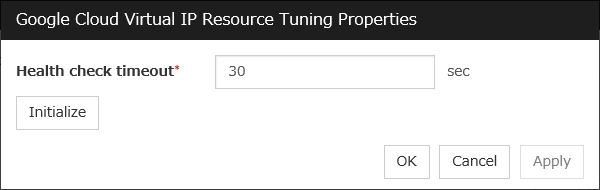
Health check timeout (5 to 999999999)
Specify a timeout value for awaiting a health check from the load balancer of Google Cloud Platform, in order to check whether the load balancer periodically performs health checks.
3.27. Understanding Google Cloud DNS resources
3.27.1. Dependencies of Google Cloud DNS resources
By default, this function does not depend on any group resource type.
3.27.2. What is an Google Cloud DNS resource?
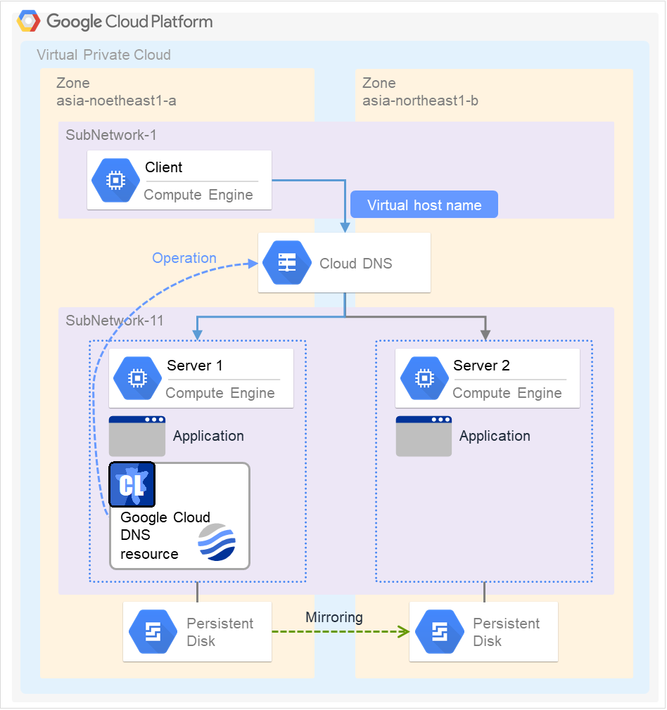
A Google Cloud DNS resource controls a Google Cloud DNS record set and DNS A record to obtain an IP address set from the virtual host name (DNS name).
A client can access the node on which failover groups are active with the virtual host name.
By using Google Cloud DNS resources, clients do not need to be aware of switching access destination node on Google Cloud DNS when a failover occurs or moving a group migration.
3.27.3. Notes on Google Cloud DNS resources
See "Setting up Google Cloud DNS resources" in "Notes when creating EXPRESSCLUSTER configuration data" in "Notes and Restrictions" in the "Getting Started Guide".
See "Google Cloud DNS resources" in " Before installing EXPRESSCLUSTER" in "Notes and Restrictions" in the "Getting Started Guide".
3.27.4. Details tab
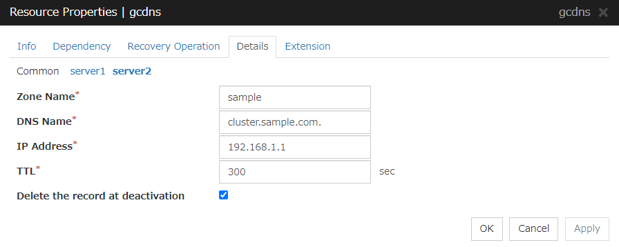
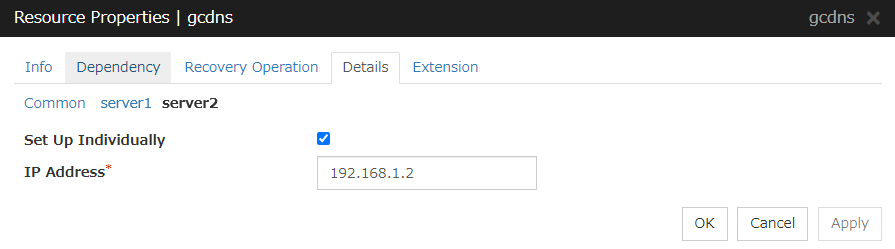
Zone Name (within 63 bytes)
Specify the name of the DNS zone to which the record set of Google Cloud DNS belongs.
DNS Name (within 253 bytes)
Specify the A record DNS name to be registered in Google Cloud DNS.
IP Address (within 39 bytes) Server Individual Setup
Specify the IP address corresponding to the virtual host name (DNS name) (IPv4). For using the IP address of each server, enter the IP address on the tab of each server. For configuring a setting for each server, enter the IP address of an arbitrary server on Common tab, and configure the individual settings for the other servers.
TTL (0 to 2147483647)
Specify the time to live (TTL) of the cache.
Delete a record set at deactivation
3.28. Understanding Oracle Cloud virtual IP resources
3.28.1. Dependencies of Oracle Cloud virtual IP resources
By default, this function does not depend on any group resource type.
3.28.2. What is an Oracle Cloud virtual IP resource?
For virtual machines in the Oracle Cloud Infrastructure environment, client applications can use a public virtual IP (VIP) address to connect to the node that constitutes a cluster. Using the VIP address eliminates the need for clients to be aware of switching between the virtual machines even after a failover or a group migration occurs.
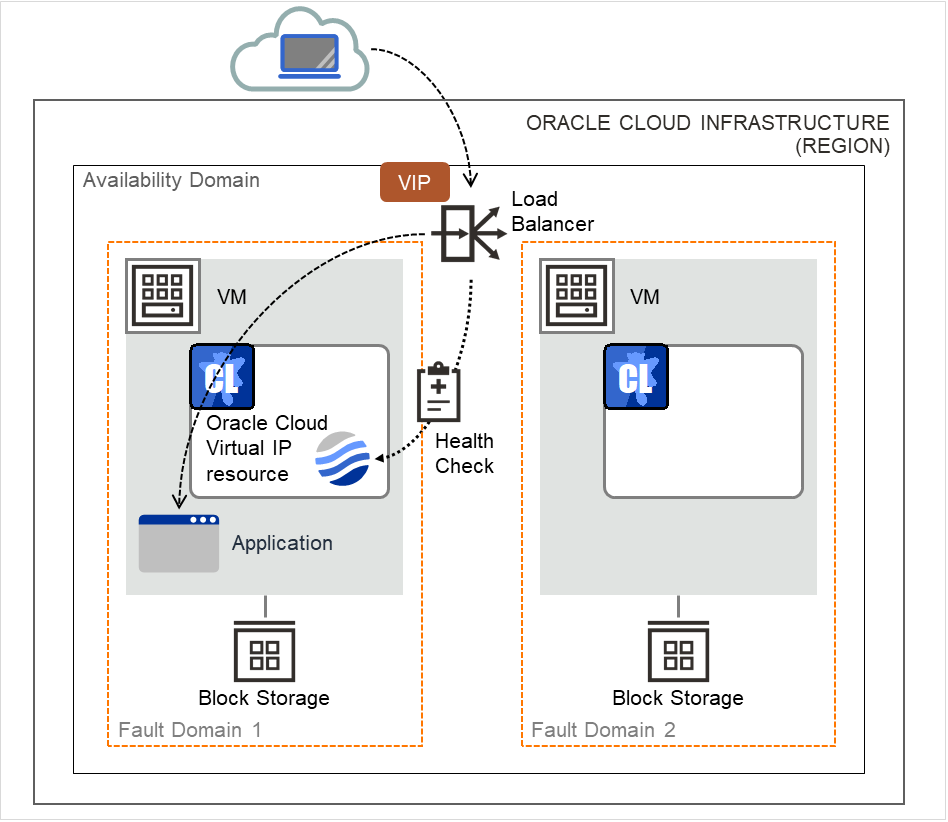
Fig. 3.117 Configuration with an Oracle Cloud Virtual IP resource
To access the cluster created in the Oracle Cloud Infrastructure environment as in the figure above, specify the port for communicating from the outside as well as the VIP (global IP) address or DNS name. The active and standby nodes of the cluster are switched by controlling the load balancer of Oracle Cloud Infrastructure (Load Balancer in the figure above) from EXPRESSCLUSTER. For this control, Health Check (in the figure above) is used.
At activation, start the control process for awaiting a health check from the load balancer of Oracle Cloud Infrastructure, and open the port specified in Port Number.
At deactivation, stop the control process for awaiting the health check, and close the port specified in Port Number.
Oracle Cloud virtual IP resources also support private load balancers of Oracle Cloud Infrastructure. For a private load balancer, the VIP address is the private IP address of Oracle Cloud Infrastructure.
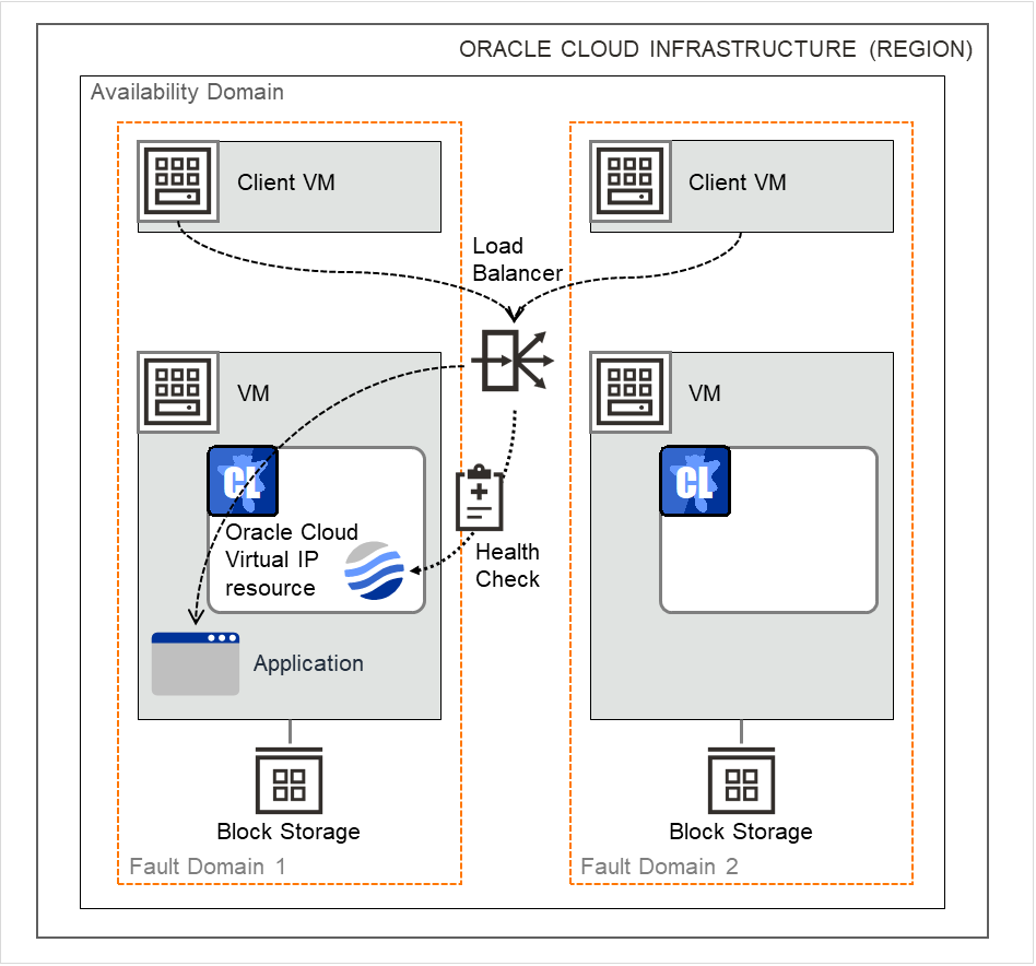
Fig. 3.118 Configuration with an Oracle Cloud Virtual IP resource (for a private load balancer)
3.28.3. Notes on Oracle Cloud virtual IP resources
If the private port is the same as the health-check port, you need not add Oracle Cloud virtual IP resources or Oracle Cloud virtual IP monitor resources.
Refer to "Getting Started Guide" -> "Notes and Restrictions" -> "Notes when creating the cluster configuration data" -> "Setting up Oracle Cloud Virtual IP resources".
3.28.4. Details tab
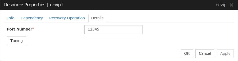
Port Number (1 to 65535)
Specify a port number to be used by the load balancer of Oracle Cloud Infrastructure for the health check of each node: the value specified as the port number in configuring the backend set for health checks. For the health check protocol, specify TCP.
Tuning
Displays the Oracle Cloud Virtual IP Resource Tuning Properties dialog box, where you can make advanced settings for the Oracle Cloud virtual IP resource.
Oracle Cloud Virtual IP Resource Tuning Properties

Health check timeout (5 to 999999999)
Specify a timeout value for awaiting a health check from the load balancer of Oracle Cloud Infrastructure, in order to check whether the load balancer periodically performs health checks.