1. Preface
1.1. Who Should Use This Guide
The EXPRESSCLUSTER X Hardware Feature Guide is intended for system administrators. Detailed information of the functions for linking with specific hardware is covered in this guide.
The guide provides supplemental information to the EXPRESSCLUSTER X Installation and Configuration Guide.
For information on the construction and the operation of clusters, refer to the guide.
1.2. How This Guide is Organized
2. Linkage with specific hardware: Provides information on linkage with specific hardware.
3. Linkage with Server Management Infrastructure: Provides information on linkage with Server Management Infrastructure.
1.3. EXPRESSCLUSTER X Documentation Set
The EXPRESSCLUSTER manuals consist of the following six guides. The title and purpose of each guide is described below.
EXPRESSCLUSTER X Getting Started Guide
This guide is intended for all users. The guide covers topics such as product overview, system requirements, and known problems.
EXPRESSCLUSTER X Installation and Configuration Guide
This guide is intended for system engineers and administrators who want to build, operate, and maintain a cluster system. Instructions for designing, installing, and configuring a cluster system with EXPRESSCLUSTER are covered in this guide.
EXPRESSCLUSTER X Reference Guide
This guide is intended for system administrators. The guide covers topics such as how to operate EXPRESSCLUSTER, function of each module,and troubleshooting. The guide is complement to the Installation and Configuration Guide.
EXPRESSCLUSTER X Maintenance Guide
This guide is intended for administrators and for system administrators who want to build, operate, and maintain EXPRESSCLUSTER-based cluster systems. The guide describes maintenance-related topics for EXPRESSCLUSTER.
EXPRESSCLUSTER X Hardware Feature Guide
This guide is intended for administrators and for system engineers who want to build EXPRESSCLUSTER-based cluster systems. The guide describes features to work with specific hardware, serving as a supplement to the Installation and Configuration Guide.
EXPRESSCLUSTER X Legacy Feature Guide
This guide is intended for administrators and for system engineers who want to build EXPRESSCLUSTER-based cluster systems. The guide describes EXPRESSCLUSTER X 4.0 WebManager, Builder, and EXPRESSCLUSTER Ver 8.0 compatible commands.
1.4. Conventions
In this guide, Note, Important, See also are used as follows:
Note
Used when the information given is important, but not related to the data loss and damage to the system and machine.
Important
Used when the information given is necessary to avoid the data loss and damage to the system and machine.
See also
Used to describe the location of the information given at the reference destination.
The following conventions are used in this guide.
Convention |
Usage |
Example |
|---|---|---|
Bold
|
Indicates graphical objects, such as fields, list boxes, menu selections, buttons, labels, icons, etc.
|
In User Name, type your name.
On the File menu, click Open Database.
|
Angled bracket within the command line |
Indicates that the value specified inside of the angled bracket can be omitted. |
clpstat -s[-h host_name] |
# |
Prompt to indicate that a Linux user has logged on as root user. |
# clpcl -s -a |
Monospace |
Indicates path names, commands, system output (message, prompt, etc.), directory, file names, functions and parameters. |
|
bold
|
Indicates the value that a user actually enters from a command line.
|
Enter the following:
# clpcl -s -a
|
italic |
Indicates that users should replace italicized part with values that they are actually working with. |
|
 In the figures of this guide, this icon represents EXPRESSCLUSTER.
1.5. Contacting NEC
For the latest product information, visit our website below:
2. Linkage with specific hardware
This chapter explains the settings for the linkage between specific hardware and EXPRESSCLUSTER.
This chapter covers:
2.2. Express5800/A1080a or Express5800/A1040a series linkage
2.2.1. Express5800/A1080a or Express5800/A1040a series linkage
Express5800/A1080a or Express5800/A1040a series linkage takes over operations by linking to EXPRESSCLUSTER if the BMC installed on a server detects an error.
This function uses BMC heartbeat resources and message receive monitor resources.
BMC heartbeat resources monitor whether the target servers are active by using the BMC network.
Setting a message receive monitor resource for Express5800/A1080a or Express5800/A1040a series linkage makes the BMC installed on the server report an error to execute a recovery operation.
2.2.2. Notes on Express5800/A1080a or Express5800/A1040a series linkage
To use this function, the following conditions must be satisfied. Hardware - The hardware and firmware of the BMC must support this function. For the available models, refer to "Servers supporting Express5800/A1080a or Express5800/A1040a series linkage" in "Installation requirements for EXPRESSCLUSTER" in the Getting Started Guide.
The ipmi service must be started in advance.
To use this function in the same environment as that for ESMPRO Agent, use the ESMPRO Agent control panel (ESMamsadm) to change the agent event operation after report from Shutdown to No Operation.
Source name: ESMCOMMONSERVICE, ID: C00001FD, C0000203, C0000454
[Starting the control panel (ESMamsadm)]
Log in as a root user.
Move to the directory containing ESMamsadm.
# cd /opt/nec/esmpro_sa/bin/
Start the control panel (ESMamsadm).
# ./ESMamsadm
[Specifying an operation after report for each monitor event]
Start the control panel (ESMamsadm) and select Agent Event Setting.
Select a source for Source Name. (Use the ↑ or ↓ key.)
Select an event ID for Event ID. (Use the ↑ or ↓ key.)
Click the Setting... button. The Monitor Event Setting window appears.
Change Operation after Report from Shutdown to No Operation.
For details, refer to the ESMPRO Agent User's Guide (Linux).
2.2.3. Creating configuration information for using Express5800/A1080a or Express5800/A1040a series linkage
The following describes, using an example, how to create the configuration information needed to use the Express5800/A1080a or Express5800/A1040a series linkage function.
Sample cluster environment
The creation of configuration information is explained below using an example for configuring a cluster environment with the following network configuration. In the figure below, disk configuration and other data are omitted because they are not directly related to the Express5800/A1080a or Express5800/A1040a series linkage function.
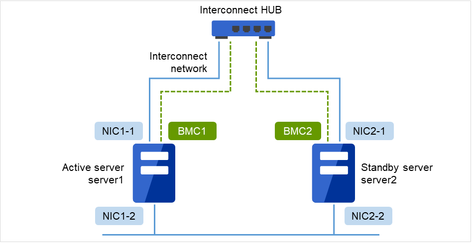
Fig. 2.1 Sample cluster environment
The following table lists sample values for the cluster configuration information that is used to configure the cluster system shown in the above figure. The following pages provide a step-by-step procedure for creating cluster configuration information for these conditions. When actually setting values, use the configuration information for the cluster to be configured.
Parameter to be set
Value
Cluster configuration
Cluster name
cluster
Number of servers
2
Number of failover groups
1
Number of monitor resources
2
Heartbeat resources
Number of LAN heartbeat resources
2
Number of COM heartbeat resources
0
Number of disk heartbeat resources
0
Number of BMC heartbeat resources
1
Server name
server1
BMC server Web console IP address
192.168.0.11 (BMC1)
Second server information
Server name
server2
BMC server Web console IP address
192.168.0.12 (BMC2)
First group
Type
Failover
Group name
failover1
Starting server
All servers
Number of group resources
-
Group resource (omitted)
-
-
-
-
-
-
Type
User-mode monitor
Monitor resource name
userw
Second monitor resource
Type
Message receive monitor
Category
BMCNOTICE
Keyword (common)
192.168.0.1 (NIC1-1)
Recovery operation
Executes the failover for the recovery target.
Recovery target
failover1
Procedure for creating cluster configuration information
The creation of cluster configuration information involves the following three basic steps: creating a cluster, creating groups, and creating monitor resources. The following shows the flow of the procedure for setting items specific to Express5800/A1080a or Express5800/A1040a series linkage. For other items, refer to "Creating cluster configuration information" in the Installation and Configuration Guide.
Note
An operation on cluster configuration information can be performed any number of times. Most settings can be modified later by using the rename function or the properties view function.
1 Creating a cluster
Create a cluster and add servers.
1-1 Adding a cluster
Add a cluster you want to construct and enter its name. This item contains no settings that are specific to Express5800/A1080a or Express5800/A1040a series linkage.
1-2 Adding servers
Add servers and set their server names, IP addresses, and other items. This item contains no settings that are specific to Express5800/A1080a or Express5800/A1040a series linkage.
1-3 Setting the network configuration
Set the network configuration between servers that constitute the cluster. Set BMC heartbeat resources as an item specific to Express5800/A1080a or Express5800/A1040a series linkage.
1-4 Setting network partition resolution resources
Set the network partition resolution resources. This item contains no settings that are specific to Express5800/A1080a or Express5800/A1040a series linkage.
2 Creating a failover group
Create a failover group that operates as a unit when failover occurs. This item contains no settings that are specific to Express5800/A1080a or Express5800/A1040a series linkage.
2-1 Adding a failover group
Add a group that operates as a unit when failover occurs. This item contains no settings that are specific to Express5800/A1080a or Express5800/A1040a series linkage.
2-2 Adding a group resource
Add a resource that constitutes a group. This item contains no settings that are specific to Express5800/A1080a or Express5800/A1040a series linkage.
3 Creating a monitor resource
Create a monitor resource that monitors the specified target in the cluster.
Adding a monitor resource (message receive monitor)
Add a monitor resource to use.
1 Procedure for creating a cluster
First, create a cluster. To the created cluster, add a server that is part of the cluster and determine the priorities of the server and heartbeat. Only steps 1 to 3 contain the settings that are specific to Express5800/A1080a or Express5800/A1040a series linkage.
1-1 Adding a cluster
This item contains no settings that are specific to Express5800/A1080a or Express5800/A1040a series linkage.
1-2 Adding servers
This item contains no settings that are specific to Express5800/A1080a or Express5800/A1040a series linkage.
1-3 Setting the network configuration
Set the network configuration between the servers that constitute the cluster.
For the communication route used for BMC heartbeat transmission (interconnect), click a cell in the Type column, and then select BMC. Click a cell in the column for each server, and then enter the BMC server Web console IP address.
1-4 Setting network partition resolution resources
This item contains no settings that are specific to Express5800/A1080a or Express5800/A1040a series linkage.

2 Creating a failover group
This step contains no settings that are specific to Express5800/A1080a or Express5800/A1040a series linkage.
3 Creating a monitor resource
Create a monitor resource that monitors the specified target in the cluster. For the Express5800/A1080a or Express5800/A1040a series linkage function, set a message receive monitor. For details on the monitor, see "2.2.4. Express5800/A1080a or Express5800/A1040a series linkage with message receive monitor resources".
3-1 Adding a monitor resource (Message receive monitor)
Add a monitor resource that monitors the reception of an error report from the server.
Click Next in Group.
The Monitor Resource List appears. Click Add.
The Monitor Resource Definition dialog box appears. Select the monitor resource type (Message receive monitor) from the Type box, and then enter the monitor resource name (mrw1) in the Name box. Click Next.
Enter the monitoring settings. Click Next without changing the default values.
Enter BMCNOTICE in the Category box and the IP address of the OS side of each server that can communicate with the BMC as the IP address of the destination of the error report in the Keyword box. Use the Monitor(special) tab because the IP addresses differ depending on the server. In this example, enter 192.168.0.1 for Common and server1 and 192.168.0.2 for server2.
Set Executing failover the recovery target for Recovery Action. For Express5800/A1080a or Express5800/A1040a series linkage, select this setting for Recovery Action.
Set a recovery target. Click Browse. In the displayed tree view, select failover1 and then click OK. failover1 is set for Recovery Target.
Click Complete.
This completes the creation of cluster configuration information that is specific to Express5800/A1080a or Express5800/A1040a series linkage.
2.2.4. Express5800/A1080a or Express5800/A1040a series linkage with message receive monitor resources
This function enables EXPRESSCLUSTER to immediately execute a recovery operation if the BMC installed on the Express5800/A1080a or Express5800/A1040a series detects an error.
When this function is not used, and the BMC detects an error, server reset and other operations are executed immediately. For this reason, required operations such as application termination are not executed.
When this function is used, even if the BMC detects an error, server reset and other operations are performed after EXPRESSCLUSTER executes recovery.
The following figure is an overview of the operation that is performed when Express5800/A1080a or Express5800/A1040a series linkage with message receive monitor resources is used.
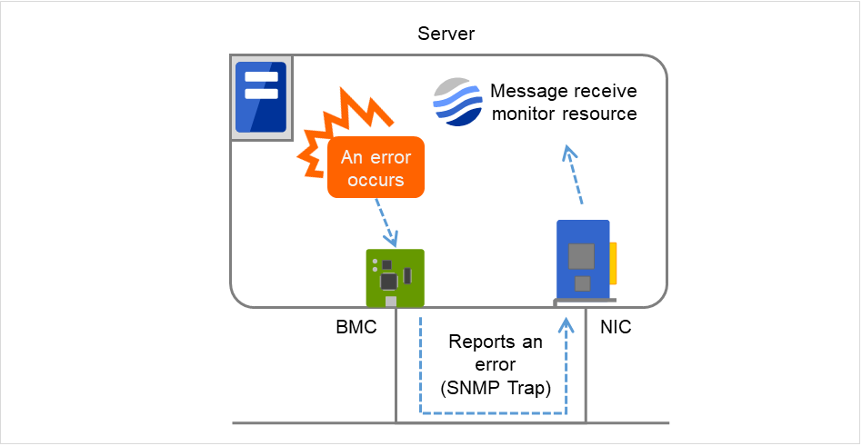
Fig. 2.2 Overview of the operation performed when Express5800/A1080a or Express5800/A1040a series linkage with message receive monitor resources is used
2.2.5. Notes on Express5800/A1080a or Express5800/A1040a series linkage with message receive monitor resources
In addition to the conditions listed in "2.2.2. Notes on Express5800/A1080a or Express5800/A1040a series linkage", the following condition must be satisfied.
Set BMCNOTICE for Category.
Unique values must be specified for Keyword on different servers. Specify the IP address and port number on the OS side connected to the BMC on each server as the destination of error reports.
2.2.6. Monitor(special) tab
For more information of other tabs, see "Monitor resource details" in the Reference Guide.

Category (within 32 bytes)
Specify a category.Specify BMCNOTICE.
Keyword (within 1023 bytes)
Specify an IP address that can communicate with the BMC on each server. In this case, specify the IP address and port number for receiving error reports.
Use individual server settings to specify the values for each server.
The port number can be omitted (default: 162). To set the port number, use the same value for all the message receive monitor resources for the same server.
The format is as follows:
<IP address> [:<Port number>]
3. Linkage with Server Management Infrastructure
This chapter provides an overview of the server management infrastructure included in Enterprise Linux with Dependable Support.
This chapter covers:
3.2. Overview of linkage between the server management infrastructure and EXPRESSCLUSTER
3.3. Setup of the function to link with the server management infrastructure
3.1. Overview of the server management infrastructure
This server management infrastructure is included in Enterprise Linux with Dependable Support. This software provides the following functions:
Recording information about failures detected by the expanded device driver
Linking with EXPRESSCLUSTER X to perform a failover when the expanded device driver detects a fatal system failure
For details, see the manual for Enterprise Linux with Dependable Support.
3.2. Overview of linkage between the server management infrastructure and EXPRESSCLUSTER
EXPRESSCLUSTER's function for linking with the server management infrastructure is not used for EXPRESSCLUSTER to perform monitoring itself. This linkage function is used for EXPRESSCLUSTER to receive messages spontaneously sent by the driver module and passively perform a failover or other processing.
The following shows an overview:
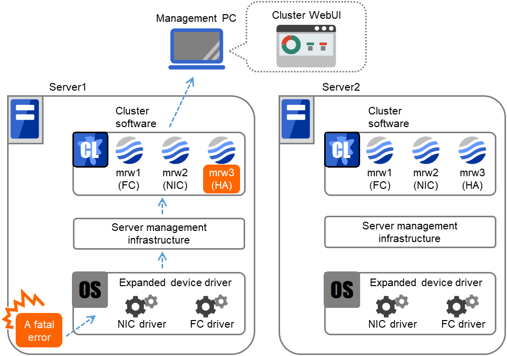
Fig. 3.1 Overview of the linkage between server management infrastructure and EXPRESSCLUSTER
If a fatal system error occurs, the expanded device driver included in Enterprise Linux with Dependable Support (hereafter referred to as the expanded driver) sends a message to EXPRESSCLUSTER through the server management infrastructure. After receiving such a message, EXPRESSCLUSTER performs the following operations.
EXPRESSCLUSTER makes the status of the corresponding message receive monitor (mrw) abnormal. The administrator can visually determine that an error was detected by checking the status using the Cluster WebUI or an EXPRESSCLUSTER command.
When a failure occurs, EXPRESSCLUSTER performs an operation failover or shuts down the OS according to the specified action.
3.3. Setup of the function to link with the server management infrastructure
For details about resources other than the message receive monitor resource, see the EXPRESSCLUSTER manuals below.
Installing EXPRESSCLUSTER
Creating EXPRESSCLUSTER configuration information
To use the function for linking with the server management infrastructure, the message receive monitor resources must be registered with the cluster . To create configuration information, register the necessary message receive monitor resources as described in the manual. For the message receive monitor resources, see "Message receive monitor resources".Uploading EXPRESSCLUSTER configuration information
3.4. Message receive monitor resources
The message receive monitor resources monitor error messages reported from outside. This section only covers the part associated with linkage with the server management infrastructure. For other cases, see "Monitor resource details" in the Reference Guide.
3.4.1. Notes on message receive monitor resources
3.4.2. Category by a message receive monitor resource
A message receive monitor resource receives the following message types when it is linked with the server management infrastructure.
3.4.3. Monitor(special) tab
For more information on the Info tab and the Monitor (common) tab, see "Monitor resource details" in the Reference Guide.

Category (within 32 bytes)
Specify a category.Be sure to select a default character string from the list box.
Keyword (within 1023 bytes)
Specify a monitor target.
3.4.4. Recovery Action tab
For more information on the Info tab and the Monitor (common) tab, see "Monitor resource details" in the Reference Guide.
Specify the recovery target and the action upon detecting an error. For message receive monitor resources, select "Restart the recovery target", " Executing failover to the recovery target", or " Execute the final action" as the action to take when an error is detected. However, if the recovery target is inactive, the recovery action is not performed.

Recovery Action
Select the action to take when a monitor error is detected.
Execute Failover to outside the Server Group
Configurable only for message receive monitor resources. Specify whether to fail over to a server group other than the active server group upon the reception of an error message.
Execute Script before Recovery Action
This setting is disabled when linking with the server management infrastructure. Execute the script before the operation to be performed upon error detection, as selected for the recovery action.
For details about the settings other than the above, see "Recovery Action tab" in "Monitor resource properties" in "Monitor resource details" in the Reference Guide.