3. Group resource details
This chapter provides information on group resources that constitute a failover group.
For overview of group resources, see " Configuring a cluster system" in the "Installation and Configuration Guide".
This chapter covers:
3.1. Group resources and supported EXPRESSCLUSTER versions
The following is the number of group resources that can be registered with a group:
Version |
Number of group resources(per group) |
|---|---|
4.0.0-1 or later |
256 |
Currently supported group resources are:
Group resource name |
Abbreviation |
Functional overview |
Supported version |
|---|---|---|---|
Exec resource |
exec |
4.0.0-1 or later |
|
Disk resource |
disk |
4.0.0-1 or later |
|
Floating IP resource |
fip |
4.0.0-1 or later |
|
Virtual IP resource |
vip |
4.0.0-1 or later |
|
Mirror disk resource |
md |
4.0.0-1 or later |
|
Hybrid disk resource |
hd |
4.0.0-1 or later |
|
Volume manager resource |
volmgr |
4.0.0-1 or later |
|
Dynamic DNS resource |
ddns |
4.0.0-1 or later |
|
AWS Elastic IP resource |
awseip |
4.0.0-1 or later |
|
AWS Virtual IP resource |
awsvip |
4.0.0-1 or later |
|
AWS Secondary IP resource |
awssip |
5.0.0-1 or later |
|
AWS DNS resource |
awsdns |
4.0.0-1 or later |
|
Azure probe port resource |
azurepp |
4.0.0-1 or later |
|
Azure DNS resource |
azuredns |
4.0.0-1 or later |
|
Google Cloud Virtual IP resource |
gcvip |
4.2.0-1 or later |
|
Google Cloud DNS resource |
gcdns |
4.3.0-1 or later |
|
Oracle Cloud Virtual IP resource |
ocvip |
4.2.0-1 or later |
|
Oracle Cloud DNS resource |
ocdns |
5.2.0-1 or later |
The group resources that currently support dynamic resource addition are as follows:
Group resource name |
Abbreviation |
Functional overview |
Supported version |
|---|---|---|---|
Exec resource |
exec |
4.0.0-1 or later |
|
Disk resource |
disk |
4.0.0-1 or later |
|
Floating IP resource |
fip |
4.0.0-1 or later |
|
Virtual IP resource |
vip |
4.0.0-1 or later |
|
Volume manager resource |
volmgr |
4.0.0-1 or later |
3.2. Attributes common to group resources
A group is a failover unit. Rules regarding the failover operations (failover policies) can be specified for a group.
3.2.1. Understanding the group type
The following type of groups exists.
- Failover groupsResources necessary to continue operations are grouped and failovers are performed on an operation basis. Up to 256 group resources can be registered with each group.
3.2.2. Understanding the group properties
The following properties can be specified for each group:
- Servers that can run the GroupSelect a server that can run the group from the servers in the cluster.Specify the order of servers that can run the group and the priority according to which the group is started.
- Startup AttributeSpecify automatic or manual startup as the group startup attribute.For automatic startup, the group is automatically started on the server that can run the group and has the highest priority when the cluster is started.For manual startup, the group is not started when the server is started. Manually start the group by using the Cluster WebUI or clpgrp command after the server is started. For details about the Cluster WebUI, see the online manual. For details about the clpgrp command, see "Operating groups (clpgrp command)" in "9. EXPRESSCLUSTER command reference" in this guide.
- Failover attributeThe failover attribute can be used to specify the failover mode. The following failover attributes can be specified.
Automatic failover
A heartbeat timeout or error detection by a group or monitor resource triggers an automatic failover.
For an automatic failover, the following options can be specified.
- Use the startup server settingsThe failover destination is determined according to the priority of the servers that can run the group.
- Fail over dynamicallyThe failover destination is determined by considering the statuses of each server's monitor resource or failover group, and then a failover is performed.
The failover destination is determined in the following way.
Determination factor
Condition
Result
Status of critical monitor resource
Error (all servers)
When there is no failover destination, proceed to failover judgment process while ignoring errors of critical monitor resources.
Normal (single server)
A normal server is used as the failover destination.
Normal (multiple servers)
Proceed to the process that compares error levels.
Perform a failover while ignoring errors of critical monitor resources
Set
Proceed to the process that ignores the status of the critical monitor resources and which compares error levels for all the activated servers.
Not set
Failover is not performed.
Number of servers with the lowest error level
1
The server that has the lowest error level is used as the failover destination.
Two or more
The operation levels are compared for those servers that have the lowest error level.
Prioritize failover policy in the server group
The server in the same server group is used as the failover destination.
Proceed to the smart failover judgment process.
Not set
Proceed to the smart failover judgment process.
Perform a smart failover
The server recommended by the smart failover is used as the failover destination.
Proceed to the running level judgment process.
Not set
Proceed to the running level judgment process.
Number of servers with the lowest running level
1
The server with the lowest running level is used as the failover destination.
Two or more
Of the activated servers, the server with the highest priority is used as the failover destination.
Note
Critical monitor resourceExclude the server that detected an error in a monitor resource from the failover destination.The monitor that is used can be set with the Cluster WebUI.Error levelNumber of monitor resources that detected errorsSmart failoverA function that assigns the server with the smallest load as the failover destination, based on the system resource information collected by the System Resource Agent. To enable this function, a System Resource Agent license must be registered on all the servers set as the failover destination and the system monitor resources must be set as the monitor resource. For detail about the system monitor resources, see "Understanding System monitor resources" in "4. Monitor resource details" in this guide.Running levelNumber of started failover groups or number of failover groups that are being started, excluding management groups
Manual failover
A failover is not automatically performed when a heartbeat timeout occurs. Manually start a failover by using the Cluster WebUI or clpgrp command. However, even when manual failover is specified, an automatic failover is performed if a group resource or monitor resource detects an error.
Note
If Execute Failover to outside the Server Group is set in eternal link monitor resource setting, dynamic failover setting and failover setting between server groups will be invalid. A failover is applied to the server that is in a server group other than the server group to which the failover source server belongs and which has the highest priority.
Failover attribute (Advanced)
Allows an advanced configuration of the automatic failover method specified in Failover Attribute.Available options are as follows:- Exclude server with error detected by specified monitor resource, from failover destinationA server with error detected by the specified monitor resources is excluded from the failover destination.This option can be enabled or disabled by selecting Use the startup server settings or Prioritize failover policy in the server group in Failover Attribute.This option is automatically enabled by selecting Fail over dynamically in Failover Attribute.
- Failover with error ignored if it is detected in all serversThis option is selectable only with the above Exclude server with error detected by specified monitor resource, from failover destination selected.The failover destination is determined regardless of errors detected in all servers (i.e., no failover destination) by the monitor resource.
Failback attribute
Specify automatic or manual failback. However, This cannot be specified when the following conditions match.
Mirror disk resource or hybrid disk resource is set to fail over group.
Failover attribute is Fail over dynamically.
For automatic failback, an automatic failback is performed when the server that has the highest priority is started after a failover.
For manual failback, no failback occurs even when the server is started.
3.2.3. Understanding failover policy
A failover policy is a priority that determines a server to be the failover destination from multiple servers. When you configure the failover policy, avoid making certain servers heavily loaded at a failover.
The following describes how servers behave differently depending on failover policies when a failover occurs using example of the server list that can fail over and failover priority in the list.
<Symbols and meaning>
Server status |
Description |
|
Normal (properly working as a cluster) |
|
Stopped (cluster is stopped) |
3-node configuration:
Group |
Priority order of servers |
||
|---|---|---|---|
1st priority server |
2nd priority server |
3rd priority server |
|
A |
Server 1 |
Server 3 |
Server 2 |
B |
Server 2 |
Server 3 |
Server 1 |
2-node configuration:
Group |
Priority order of servers |
|
|---|---|---|
1st priority server |
2nd priority server |
|
A |
Server 1 |
Server 2 |
B |
Server 2 |
Server 1 |
It is assumed that the group startup attributes are set to auto startup and the failback attributes are set to manual failback for both Group A and B.
For groups belonging to exclusion rules in which exclusive attributes are Normal or Absolute, the server which they start up or fail over is determined by the failover priority to the server. If a group has two or more servers of the same failover priority, it is determined by the order of numbers, the specific symbols and alphabets of the group name. For details on the failover exclusive attribute, refer to "Understanding Exclusive Control of Group".
When Group A and B do not belong to the exclusion rules:
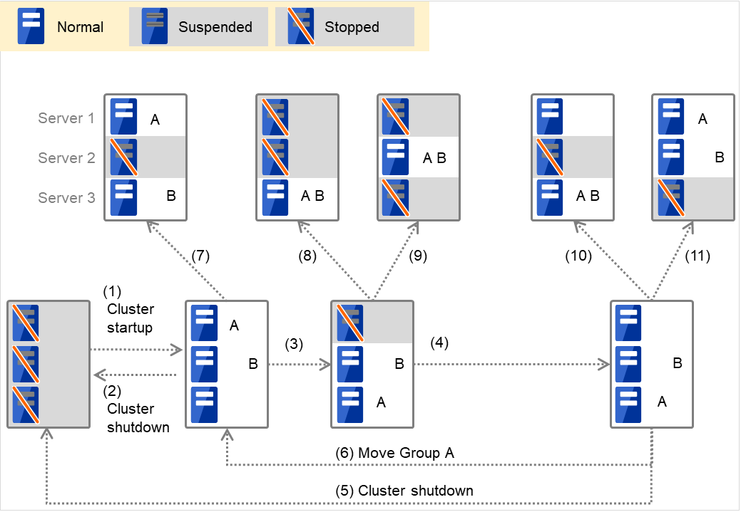
Fig. 3.1 The status of each server, and the startup status of Groups A and B
Cluster startup
Cluster shutdown
Failure of Server 1 Fails over to the next priority server.
Server 1 power on
Cluster shutdown
Move group A
Failure of Server 2: Fails over to the next priority server.
Failure of Server 2: Fails over to the next priority server.
Failure of Server 3: Fails over to the next priority server.
Failure of Server 2: Fails over to the next priority server.
Failure of Server 3: Fails over to the next priority server.
When Group A and B belong to the exclusion rules in which the exclusive attribute is set to Normal:
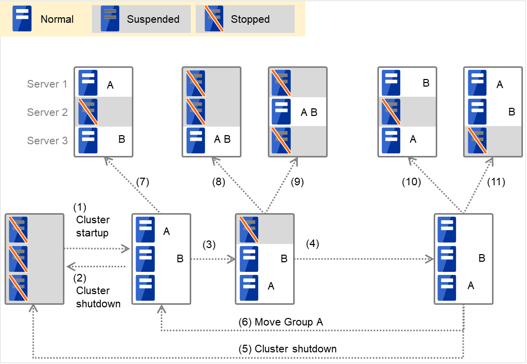
Fig. 3.2 The status of each server, and the startup status of Groups A and B (whose exclusive attributes are Normal)
Cluster startup
Cluster shutdown
Failure of Server 1: Fails over to a server where no normal exclusive group is active.
Server 1 power on
Cluster shutdown
Move Group A
Failure of Server 2: Fails over to a server where a normal exclusive group is not active.
Failure of Server 2: There is no server where a normal exclusive group is not active, but failover to the server because there is a server that can be started.
Failure of Server 3: There is no server where a normal exclusive group is not active, but failover to the server because there is a server that can be started.
Failure of Server 2: Fails over to a server where a normal exclusive group is not active.
Failure of Server 3: Fails over to a server where a normal exclusive group is not active.
When Group A and B belong to the exclusion rules in which the exclusive attribute is set to Absolute:
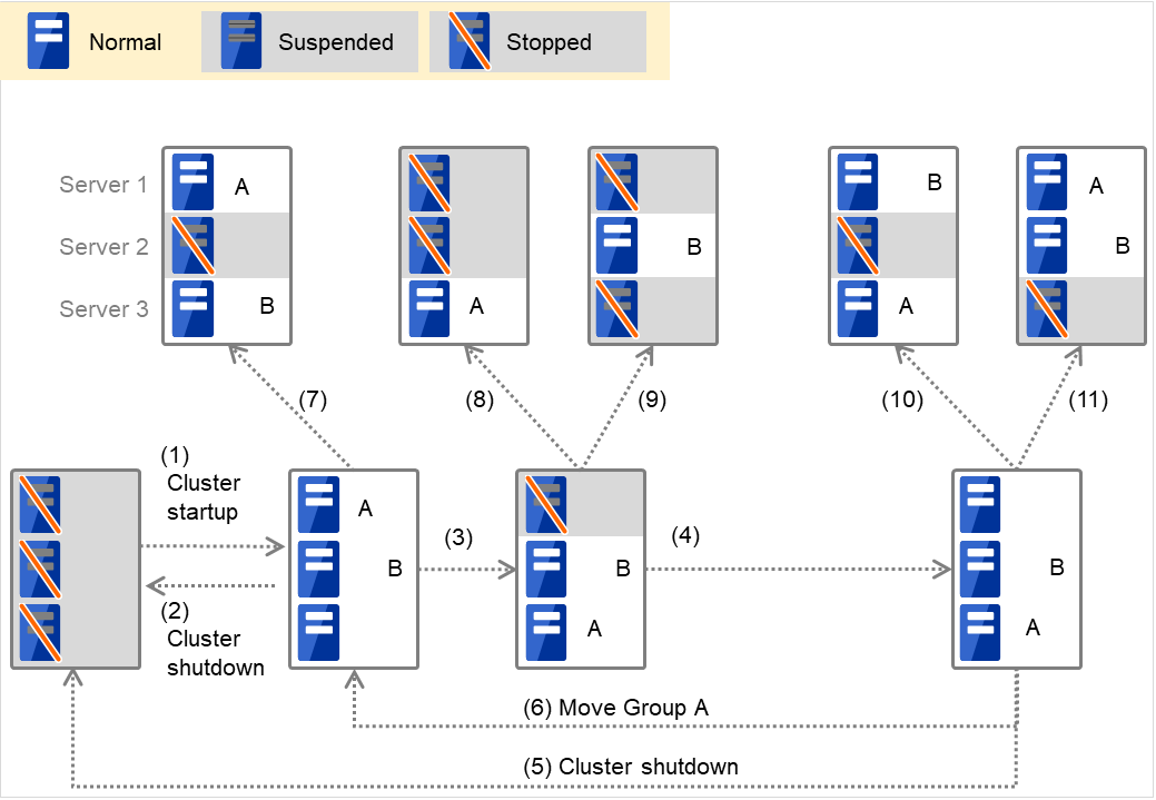
Fig. 3.3 The status of each server, and the startup status of Groups A and B (whose exclusive attributes are Absolute)
Cluster startup
Cluster shutdown
Failure of Server 1: Fails over to the next priority server.
Server 1 power on
Cluster shutdown
Move Group A
Failure of Server 2: Fails over to the next priority server.
Failure of Server 2: Does not failover (GroupB stops).
Failure of Server 3: Does not failover (GroupA stops).
Failure of Server 2: Fails over to the server where no absolute exclusive group is active.
Failure of Server 3: Fails over to the server where no absolute exclusive group is active.
For Replicator (two-server configuration) When Group A and B do not belong to the exclusion rules:
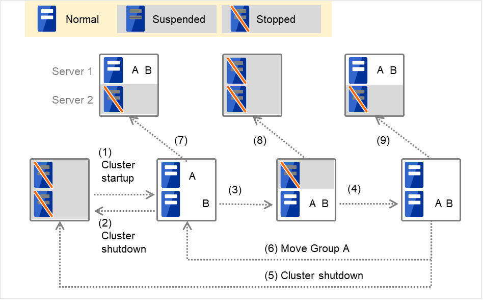
Fig. 3.4 The status of each server, and the startup status of Groups A and B (with Replicator)
Cluster startup
Cluster shutdown
Failure of Server 1: Fails over to the standby server of GroupA.
Server 1 power on
Cluster shutdown
Move Group A
Failure of Server 2: Fails over to the standby server of GroupB.
Failure of Server 2
Failure of Server 3: Fails over to the standby server.
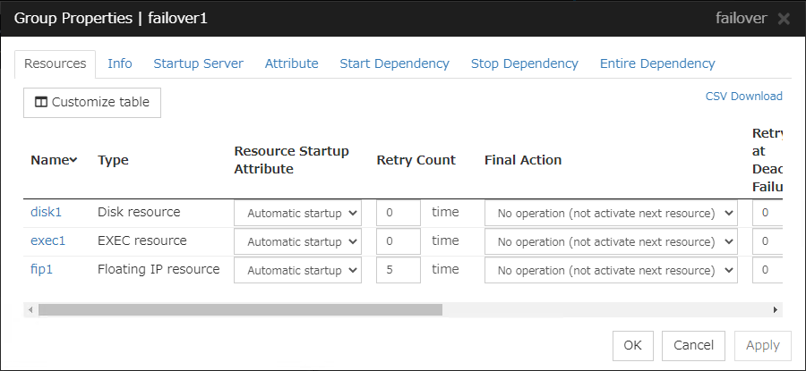
3.2.4. Operations at detection of activation and deactivation failure
When an activation or deactivation error is detected, the following operations are performed:
When an error in activation of group resources is detected:
When an error in activation of group resources is detected, activation is retried.
When activation retries fail as many times as the number set to Retry Count at Activation Failure, a failover takes place.
If the failover fails as many times as the number set to Failover Threshold, the final action is performed.
When an error in deactivation of group resources is detected:
When an error in deactivation of group resources is detected, deactivation is retried.
When deactivation retries fail as many times as the number set to Retry Count at Deactivation Failure, the final action is performed.
Note
The following describes how an error in activation of a group resource is detected:

Fig. 3.5 Flow of operation on detecting a group resource activation failure (1)
The activation of Disk resource 1 fails due to an fsck error, a mount error, or other causes.
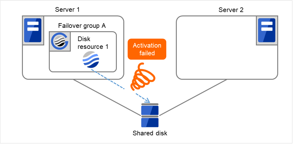
Fig. 3.6 Flow of operation on detecting a group resource activation failure (2)
The activation of Disk resource 1 is retried up to three times (activation retry count).
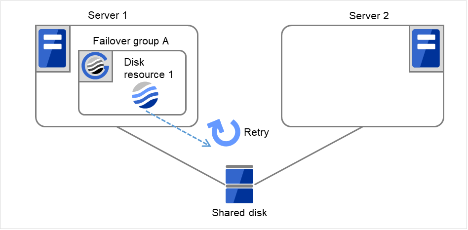
Fig. 3.7 Flow of operation on detecting a group resource activation failure (3)
- The failover of Failover group A is started.Failover Threshold represents how many times failover is performed on each server.So this is the first failover on Server 1.
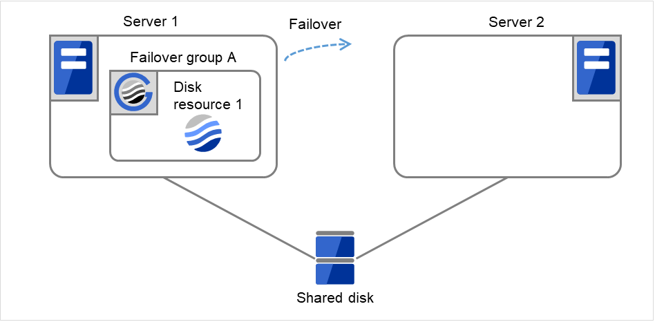
Fig. 3.8 Flow of operation on detecting a group resource activation failure (4)
- Disk resource 1 starts to be activated (e.g. for mounting the file system).If a failure occurs on the way, the activation is retried up to three times.
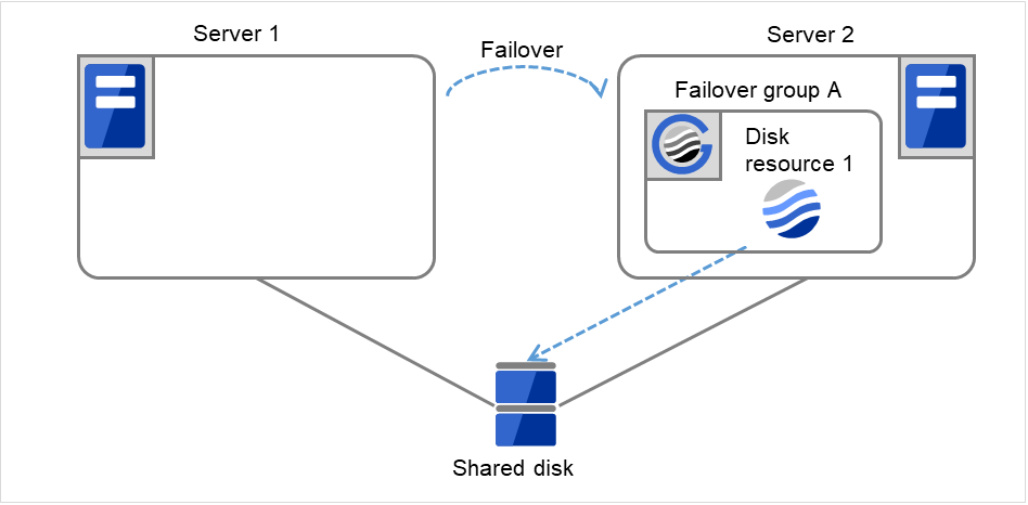
Fig. 3.9 Flow of operation on detecting a group resource activation failure (5)
- If the specified retry count is exceeded for the activation of Disk resource 1 on Server 2 as well, Failover group A starts to be failed over.This is the first failover on Server 2.
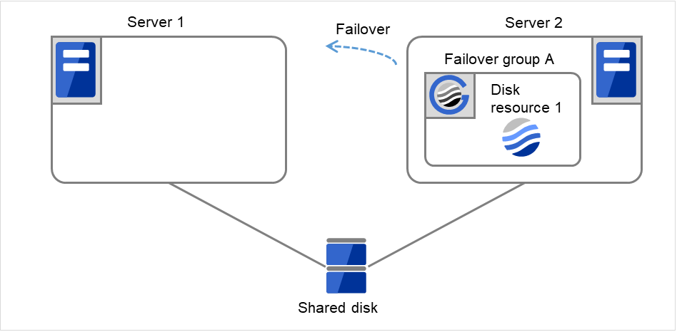
Fig. 3.10 Flow of operation on detecting a group resource activation failure (6)
On Server 1, the activation of Disk Resource 1 is started. If a failure occurs on the way, the activation is retried up to three times.

Fig. 3.11 Flow of operation on detecting a group resource activation failure (7)
- If the specified retry count is exceeded for the activation of Disk resource 1 on Server 1 as well, the specified Final Action is started. No failover is performed then, because Failover Threshold is set at 1.Final Action means the action to be taken after the specified failover retry count is exceeded.Here, Failover group A starts to be stopped.
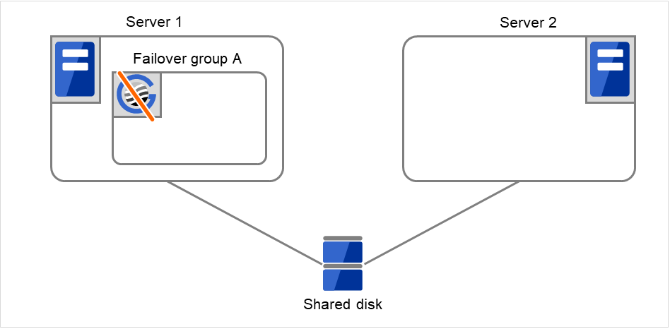
Fig. 3.12 Flow of operation on detecting a group resource activation failure (8)
3.2.5. Script before final action
When a group resource activation error is detected, a script before final action can be executed before the last action during detection of a deactivation error.
Environment variables used with a script before final action
When executing a script, EXPRESSCLUSTER sets information such as the state in which it is executed (when an activation error occurs, when a deactivation error occurs) in the environment variables.
In the script, processing that is appropriate for the system operation can be described using the environment variables listed below as branch conditions.
Environment variable |
Value |
Description |
|---|---|---|
CLP_TIMING
...Execution timing
|
START |
Executes a script before final action in the event of a group resource activation error. |
STOP |
Executes a script before final action in the event of a group resource deactivation error. |
|
CLP_GROUPNAME
...Group name
|
Group name |
Indicates the name of the group containing the group resource in which an error that causes the script before final action to be executed is detected. |
CLP_RESOURCENAME
...Group resource name
|
Group resource name |
Indicates the name of the group resource in which an error that causes the script before final action to be executed is detected. |
Flow used to describe a script before final action
The following explains the environment variables in the previous topic and an actual script, associating them with each other.
Example of a script before final action in the event of an activation error
#!/bin/sh

# ***************************************
# *           preactaction.sh
# ***************************************

ulimit -s unlimited
echo "START"

# Refer to the environment variable of the script execution factor to determine the subsequent process.
if [ "$CLP_TIMING" = "START" ]
then
    # Here, write a recovery process to be performed before the final action on an activation failure.
    #
else
    echo "NO_CLP"
fi

echo "EXIT"
exit 0
Tips for creating a script before final action
Note the following when creating a script:
If the script contains a command that will take some time to execute, always leave a trace that will indicate the completion of the execution of that command. If a problem occurs, you can use this information to isolate the failure. One way of leaving such a trace is to use clplogcmd.
- Method of describing in a script by using clplogcmdUsing clplogcmd, you can output messages to the Alert logs of Cluster WebUI or syslog of the OS. For details on the clplogcmd command, see "Outputting messages (clplogcmd command)" in "9. EXPRESSCLUSTER command reference" in this guide.
(Example: Script image)
clplogcmd -m "recoverystart.."
recoverystart
clplogcmd -m "OK"
Notes on script before final action
Stack size of the commands and application to be started from a script
A recovery script and a script before recovery action are executed with the stack size set to 2 MB. For this reason, if the commands and applications to be started from the script require a stack size of 2 MB or greater, a stack overflow will occur.If a stack overflow occurs, set the stack size before starting the commands and applications.Condition that a script before final action is executed
A script before final action is executed before the final action upon detection of a group resource activation or deactivation failure. Even if No operation (Next Resources Are Activated/Deactivated) or No operation (Next Resources Are Not Activated/Deactivated) is set as the final action, a script before final action is executed.If the final action is not executed because the maximum restart count has reached the upper limit or by the function to suppress the final action when all other servers are being stopped, a script before final action is not executed.
3.2.6. Script Before and After Activation/Deactivation
An arbitrary script can be executed before and after activation/deactivation of group resources.
Environment variables used with a script after activation/deactivation
When executing a script, EXPRESSCLUSTER sets information such as the state in which it is executed (before activation, after activation, before deactivation, or after deactivation) in the environment variables.
Environment variable |
Value |
Description |
|---|---|---|
CLP_TIMING
...Execution timing
|
PRESTART |
Executes a script before a group resource is activated. |
POSTSTART |
Executes a script after a group resource is activated. |
|
PRESTOP |
Executes a script before a group resource is deactivated. |
|
POSTSTOP |
Executes a script after a group resource is deactivated. |
|
CLP_GROUPNAME
...Group name
|
Group name |
Indicates the group name of the group resource containing the script. |
CLP_RESOURCENAME
...Group resource name
|
Group resource name |
Indicates the name of the group resource containing the script. |
Flow used to describe a script before and after activation/deactivation
The following explains the environment variables in the previous topic and an actual script, associating them with each other.
Example of a script before and after activation/deactivation
#!/bin/sh
#***********************************************
#                rscextent.sh                  *
#***********************************************
ulimit -s unlimited
echo "START"

if [ "$CLP_TIMING" = "PRESTART" ]
then
    echo "$CLP_GROUPNAME"
    echo "$CLP_RESOURCENAME"
    # Here, write any process to be performed before the resource activation.
    #

elif [ "$CLP_TIMING" = "POSTSTART" ]
then
    echo "$CLP_GROUPNAME"
    echo "$CLP_RESOURCENAME"
    # Here, write any process to be performed after the resource activation.
    #

elif [ "$CLP_TIMING" = "PRESTOP" ]
then
    echo "$CLP_GROUPNAME"
    echo "$CLP_RESOURCENAME"
    # Here, write any process to be performed before the resource deactivation.
    #

elif [ "$CLP_TIMING" = "POSTSTOP" ]
then
    echo "$CLP_GROUPNAME"
    echo "$CLP_RESOURCENAME"
    # Here, write any process to be performed after the resource deactivation.
    #

fi
echo "EXIT"
exit 0
Tips for creating a script before and after activation/deactivation
Note the following when creating a script:
If the script contains a command that will take some time to execute, always leave a trace that will indicate the completion of the execution of that command. If a problem occurs, you can use this information to isolate the failure. One way of leaving such a trace is to use clplogcmd.
- Method of describing in a script by using clplogcmdUsing clplogcmd, you can output messages to the Alert logs of Cluster WebUI or syslog of the OS. For details on the clplogcmd command, see "Outputting messages (clplogcmd command)" in "9. EXPRESSCLUSTER command reference" in this guide.
(Example: Script image)
clplogcmd -m "start.."
:
clplogcmd -m "OK"
Notes on script before and after activation/deactivation
- Stack size of the commands and application to be started from a scriptA script before and after activation/deactivation is executed with the stack size set to 2 MB. For this reason, if the commands and applications to be started from the script require a stack size of 2 MB or greater, a stack overflow will occur.If a stack overflow occurs, set the stack size before starting the commands and applications.
3.2.7. Reboot count limit
If the action which is accompanied by OS reboot is selected as the final action to be taken when any error in activation or deactivation is detected, you can limit the number of shutdowns or reboots caused by detection of activation or deactivation errors.
This maximum reboot count is the upper limit of reboot count of each server.
Note
The maximum reboot count is the upper limit of reboot count of a server because the number of reboots is recorded per server.
The number of reboots that are taken as a final action in detection of an error in group activation or deactivation and those by a monitor resource are recorded separately.
If the time to reset the maximum reboot count is set to zero (0), the number of reboots will not be reset. Run the clpregctrl command to reset this number. For details on the clpregctrl command, see "Controlling reboot count (clpregctrl command)" in "9. EXPRESSCLUSTER command reference".
The following describes the flow of operations when the limitation of reboot count is set as shown below:
As a final action, Stop cluster daemon and reboot OS is executed once because the maximum reboot count is set to one (1).
If group activation is successful at a reboot following the cluster shutdown, the reboot count is reset after 10 minutes because the time to reset maximum reboot count is set to 10 minutes.
- The following figure illustrates that Servers 1 and 2 are connected to the shared disk.With Failover group A on Server 1, Disk resource 1 will start to be activated (e.g. for mounting the file system).

Fig. 3.13 Process with the limited number of reboots (1)
Server 1
Server 2
Maximum reboot count
1
1
Reboot count
0
0
The activation of Disk resource 1 fails due to an fsck error, a mount error, or other causes.

Fig. 3.14 Process with the limited number of reboots (2)
Server 1
Server 2
Maximum reboot count
1
1
Reboot count
0
0
- Stop the cluster service, and then reboot the OS. Since both Retry Count at Activation Failure and Failover Threshold are set at zero (0), the final action is taken.On Server 1, the number of reboots is recorded as 1.
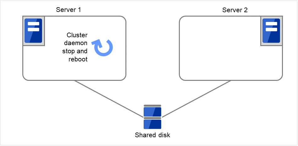
Fig. 3.15 Process with the limited number of reboots (3)
Server 1
Server 2
Maximum reboot count
1
1
Reboot count
1
0
The failover of Failover group A is started.
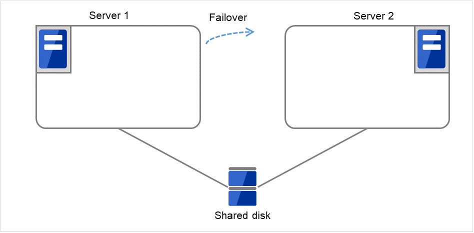
Fig. 3.16 Process with the limited number of reboots (4)
Server 1
Server 2
Maximum reboot count
1
1
Reboot count
1
0
- Disk resource 1 starts to be activated (e.g. for mounting the file system).The resource activation succeeds on Server 2, and the reboot is completed on Server 1.

Fig. 3.17 Process with the limited number of reboots (5)
Server 1
Server 2
Maximum reboot count
1
1
Reboot count
1
0
Start the failover of Failover group A by using the clpgrp command or Cluster WebUI.

Fig. 3.18 Process with the limited number of reboots (6)
Server 1
Server 2
Maximum reboot count
1
1
Reboot count
1
0
Disk resource 1 starts to be activated (e.g. for mounting the file system).
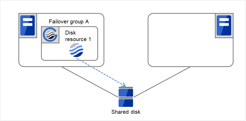
Fig. 3.19 Process with the limited number of reboots (7)
Server 1
Server 2
Maximum reboot count
1
1
Reboot count
1
0
- The activation of Disk resource 1 fails due to an fsck error, a mount error, or other causes.The final action is not taken, because the reboot count has reached its maximum.Even after 10 minutes pass, the reboot count is not reset.An activation failure occurs in Failover Group A.

Fig. 3.20 Process with the limited number of reboots (8)
Server 1
Server 2
Maximum reboot count
1
1
Reboot count
1
0
- Eliminate the disk error that caused the activation failure of Disk resource 1.After that, shut down the cluster by using the clpstdn command or Cluster WebUI. Then start the reboot.
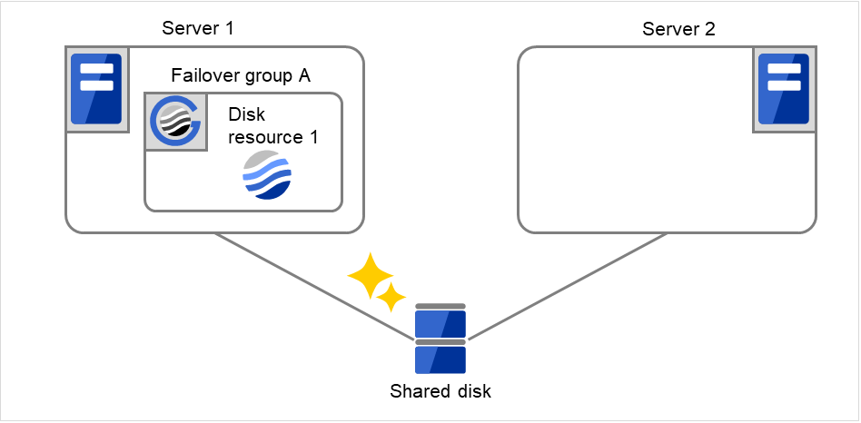
Fig. 3.21 Process with the limited number of reboots (9)
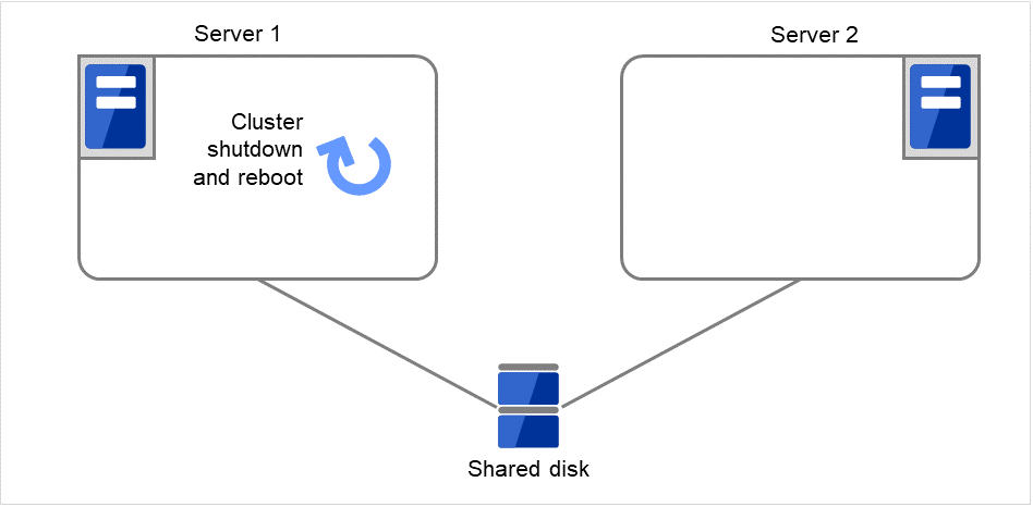
Fig. 3.22 Process with the limited number of reboots (10)
Server 1
Server 2
Maximum reboot count
1
1
Reboot count
1
0
- Starting up Failover group A succeeds.After 10 minutes pass, the reboot count is reset.Next time an activation failure occurs in Disk resource 1 during a startup of Failover group A, the final action will be taken.
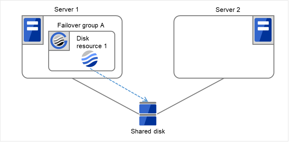
Fig. 3.23 Process with the limited number of reboots (11)
Server 1
Server 2
Maximum reboot count
1
1
Reboot count
1
0
3.2.8. Resetting the reboot count
Run the clpregctrl command to reset the reboot count. For details on the clpregctrl command, see "Controlling reboot count (clpregctrl command)" in "9. EXPRESSCLUSTER command reference" in this guide.
3.2.9. Checking a double activation
When a group is started, it is possible to check whether a double activation will occur or not.
- If a double activation is determined not to occur:A group startup begins.
- If a double activation is determined to occur (if a timeout occurs):A group startup does not begin. If the server attempts to start up the group, that group is stopped.
Note
If a single resource is started while its relevant group is stopped, a double activation check will be performed. However, if a single resource is started while any resource in the group is activated, a double activation check will not be performed.
If there are no floating IP resources for the group for which Execute Multi-Failover-Service Check is selected, a double activation is not executed and the group startup begins.
If a double activation is determined to occur, the statuses of groups and resources may not match among servers.
3.2.10. Understanding setting of group start dependence and group stop dependence
You can set the group start and stop order by setting group start dependence and group stop dependence.
When group start dependence is set:
For group start, start processing of this group is performed after start processing of the group subject to start dependence completes normally.
For group start, if a timeout occurs in the group for which start dependence is set, the group does not start.
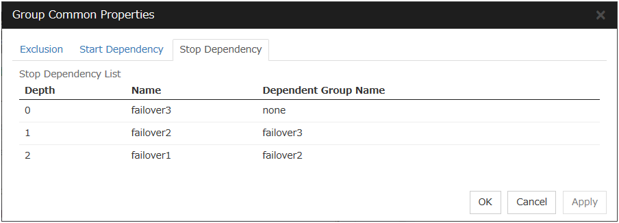
When group stop dependence is set:
For group stop, stop processing of this group is performed after stop processing of the group subject to stop dependence completes normally.
If a timeout occurs in the group for which stop dependence is set, the group stop processing continues.
Stop dependence is performed according to the conditions specified in Cluster WebUI.
To display the settings made for group start dependence and group stop dependence, click group properties in the config mode of Cluster WebUI and then click the Start Dependency tab and the Stop Dependency tab.
Depths for group start dependence are listed below as an example.


Fig. 3.24 Order of starting groups
The following explains group start execution using examples of simple status transition.
When two servers have three groups
Group failover policy
Group A Server 1Group B Server 2Group C Server 1 -> Server 2
Group start dependence setting
Group A Start dependence is not set.Group B Start dependence is not set.Group C Group A start dependence is set.Group C Start dependence is set when Group C is started by the server of Group B.
When Server 1 starts Group A and Group C
Server 1 starts Group C after Group A has been started normally.
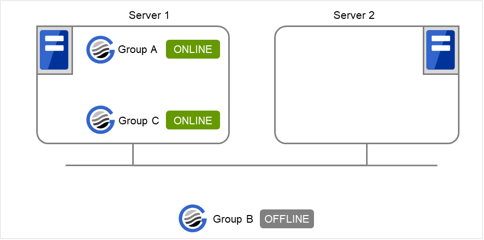
Fig. 3.25 Server 1 starts Group A and Group C
When Server 1 starts Group A and Server 2 starts Group C
Server 2 starts Group C after Server 1 has started Group A normally.
Wait Only when on the Same Server is not set, so Group A start dependence by another server is applied.
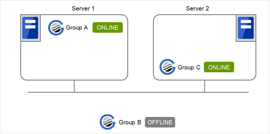
Fig. 3.26 Server 1 starts Group A and Server 2 starts Group C
When Server 1 starts Group C and Server 2 starts Group B
Server 1 starts Group C without waiting for the normal start of Group B. Group C is set to wait for Group B start only when it is started by the same server. However, start dependence is not applied to Group C because Group B is set such that it is not started by Server 1.
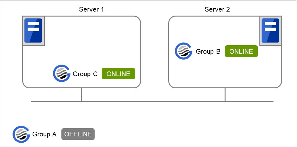
Fig. 3.27 Server 1 starts Group C and Server 2 starts Group B
When Server 1 starts Group A and Group C
If Server 1 fails in Group A start, Group C is not started.
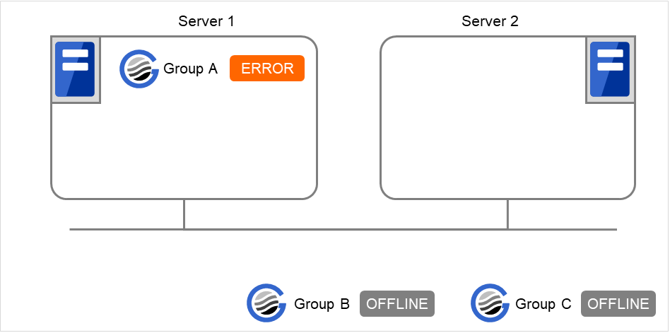
Fig. 3.28 Failing in starting Group A, Server 1 does not start Group C
When Server 1 starts Group A and Group C
If Server 1 fails in Group A start and a failover occurs in Server 2 due to Group A resource recovery, Server 2 starts Group A and then Server 1 starts Group C.
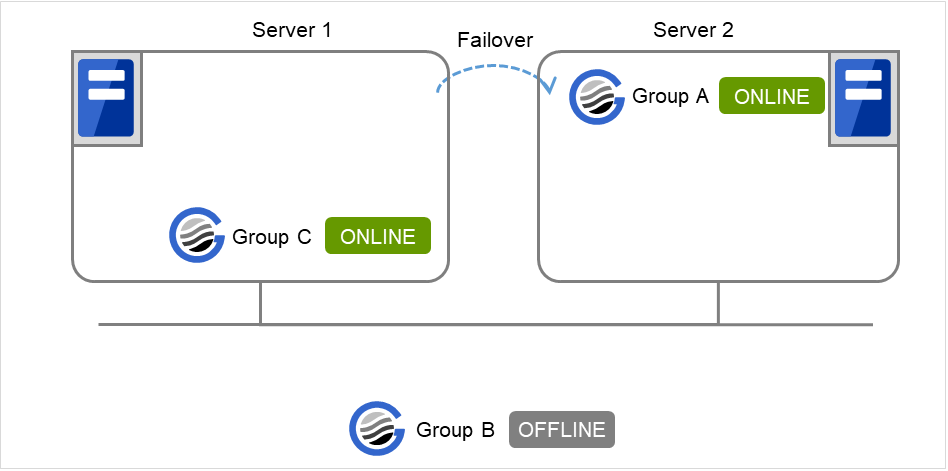
Fig. 3.29 GroupA fails over to Server 2, and Group C is started on Server 1
When Server 1 starts Group A and Group C
If a Group A start dependence timeout occurs on Server 1, Group C is not started.
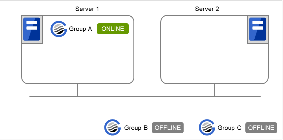
Fig. 3.30 Server 1 starts Group A
When Server 1 starts only Group C
Server 1 has not started Group A, so a start dependence timeout occurs. If this timeout occurs, Group C is not started.
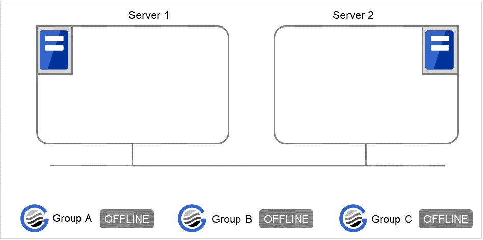
Fig. 3.31 Server 1 does not start Group A or Group C
Note
When a group is started, there is no function to automatically start the group for which start dependence is set.
The group is not started if a timeout occurs in the group for which start dependence is set.
The group is not started if the group for which start dependence is set fails to start.
If the group for which start dependence is set contains a normally started and a normally stopped resource, the group is judged to have started normally.
When a group is stopped, there is no function to automatically stop the group for which stop dependence is set.
The group stop processing continues if a timeout occurs in the group for which stop dependence is set.
The group stop processing continues if the group for which stop dependence is set fails to stop.
The group stop processing or resource stop processing by the Cluster WebUI or clpgrp command does not apply stop dependence. Stop dependence is applied according to the setting (when the cluster or a server stops) made with the Cluster WebUI.
If a start waiting timeout occurs at the time of a failover, the failover fails.
3.2.11. Understanding Exclusive Control of Group
The Failover exclusive attributes set exclusive attributes of the group at failover. However, they cannot set any attribute under the following conditions:
When failover attribute is one of Fail over dynamically, Prioritize failover policy in the server group or Enable only manual failover among the server groups.
The settable failover exclusive attributes are as follows:
Off
Exclusion is not performed at failover. Failover is performed on the server of the highest priority among the servers that can fail over.
Normal
Exclusion is performed at failover. Failover is performed on the server on which the other normal exclusion groups are not started and which is given the highest priority among the servers that can run the group.
However, if the other normal exclusion groups have already been started on all servers that the failover can be performed, exclusion is not performed. Failover is performed on the server that is given the highest priority among the servers on which failover can be performed.
Absolute
Exclusion is performed at failover. Failover is performed on the server on which the other absolute exclusion groups are not started and which is given the highest priority among the servers that can run the group.
However, failover is not performed if the other absolute exclusion groups have already been started on all servers on which failover can be performed.
Note
Exclusion is not performed to the groups with different exclusion rules. Exclusive control is performed only among the groups with the same exclusion rule, according to the set exclusion attribute. In either case, exclusion is not performed with the no-exclusion group. For details on the failover exclusive attribute, see "Understanding failover policy". Furthermore, For details on the settings of the exclusion rules, see "Group common properties".
3.2.12. Understanding server groups
This section explains about server groups.
Server groups are mainly groups of servers which are required when hybrid disk resources are used.
Upon using hybrid disk resources in a shared disk device, servers connected by the same shared disk device are configured as a server group.
Upon using hybrid disk resources in a disk which is not shared, a server is configured as a server group.
Of a server group, one (mirroring source/destination) server uses hybrid disk resources on a shared disk.
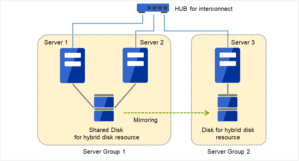
Fig. 3.32 Server groups
3.2.13. Understanding the settings of dependency among group resources
By specifying dependency among group resources, the order of activating them can be specified.
When the dependency among group resources is set:
When activating a failover group that a group resource belongs to, its activation starts after the activation of the Dependent Resources is completed.
When deactivating a group resource, the deactivation of the "Dependent Resources" starts after the deactivation of the group resource is completed.
Depths for group start dependence are listed below as an example.


Fig. 3.33 Example of a group resource activation order

Fig. 3.34 Example of a group resource deactivation order
3.2.14. Setting group resources for individual server
Some setting values of group resources can be configured for individual servers. On the properties of resources which can be set for individual servers, tabs for each server are displayed on the Details tab.
The following resources can be set for individual servers.
Group resource name |
Supported version |
|---|---|
Disk resource |
4.0.0-1 or later |
Floating IP resource |
4.0.0-1 or later |
Virtual IP resource |
4.0.0-1 or later |
Mirror disk resource |
4.0.0-1 or later |
Hybrid disk resource |
4.0.0-1 or later |
Dynamic DNS resource |
4.0.0-1 or later |
AWS Elastic IP resource |
4.0.0-1 or later |
AWS Virtual IP resource |
4.0.0-1 or later |
AWS Secondary IP resource |
5.0.0-1 or later |
AWS DNS resource |
4.0.0-1 or later |
Azure DNS resource |
4.0.0-1 or later |
Google Cloud DNS resource |
4.3.0-1 or later |
Oracle Cloud DNS resource |
5.2.0-1 or later |
Note
Some parameters of Virtual IP resources, AWS Elastic IP resources, AWS Virtual IP resources, AWS Secondary IP resources, Azure DNS resources, Google Cloud DNS resources and Oracle Cloud DNS resources should be configured for individual servers.
For parameters that can be set for individual servers, see the descriptions of parameters on each group resource. These parameters are marked with "Server Individual Setup".
In this example, the server individual setup for a Floating IP resource is explained.

Server Individual Setup
Parameters that can be set for individual servers on a Floating IP resource are displayed.
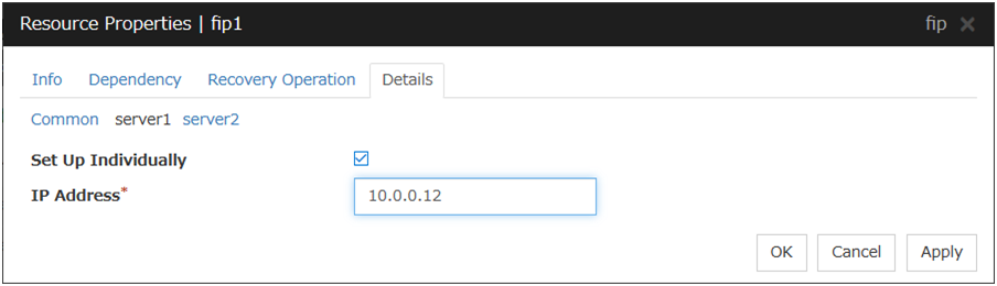
Set Up Individually
Click the tab of the server on which you want to configure the server individual setting, and select this check box. The boxes for parameters that can be configured for individual servers become active. Enter required parameters.
Note
When setting up a server individually, you cannot select Tuning.
3.3. Group common properties
3.3.1. Exclusion tab
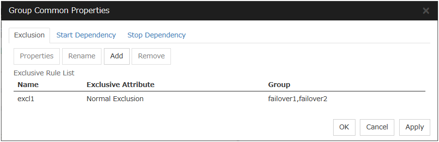
Add
Add exclusion rules. Select Add to display the Definition of Exclusion Rule dialog box.
Remove
The confirmation dialog box is displayed.
Rename
The change server group name dialog box of the selected exclusion rule is displayed.
There are the following naming rules.
Up to 31 characters (31 bytes).
Names cannot start or end with a hyphen (-) or a space.
A name consisting of only numbers is not allowed.
Names should be unique (case-insensitive) in the exclusion rule.

Properties
Display the properties of the selected exclusion rule.
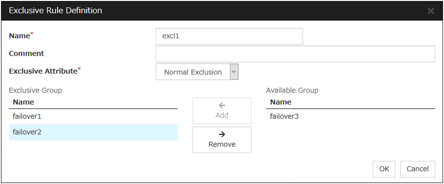
Definition of exclusion rule
The name of the exclusion rule and the exclusive attribute are set. Either Normal or Absolute can be set for an exclusive attribute. Normal can be set just one time, whereas Absolute can be set more than one time. If an exclusion rule in which Normal is set already exists, Normal cannot be set any more.
Name
Display the exclusion rule name.
Exclusive Attribute
Display the exclusive attribute set in the exclusion rule.
Group
Display the list of failover group names which belong to the exclusion rule.
After selecting a group which you want to register into the exclusion rule from Available Group, press Add. Exclusive Group displays groups registered into the exclusion rule. A failover group added in another exclusion rule is not displayed on Available Group.

3.4. Group properties
3.4.1. Resources tab
3.4.2. Info tab
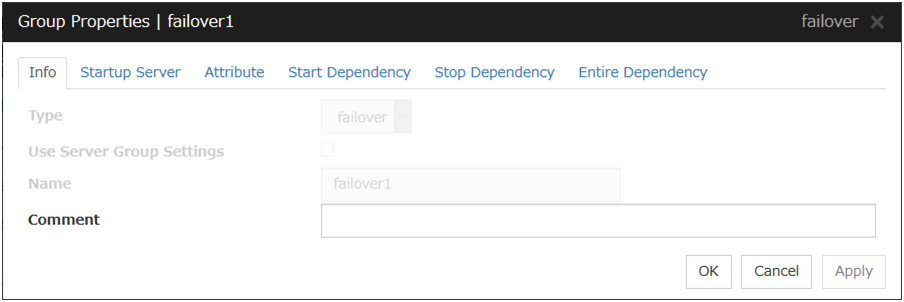
Type
The group type is displayed.
Use Server Group Settings
Name
The group name is displayed.
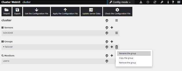
Changing the group name
click others, and then select Rename the group.
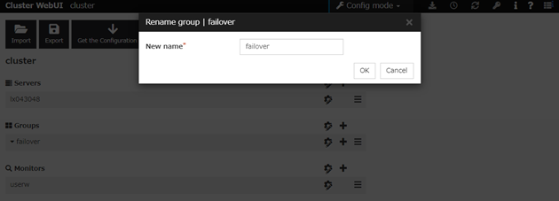
A dialog box to rename group is displayed.
Naming rules
Only alphanumeric characters, hyphen (-), underscore (_) and space are allowed for names.
Up to 31 characters (31 bytes)
Names cannot start or end with a hyphen (-) or space.
Comment (Within 127 bytes)
Enter a comment for group. Use only one-byte alphabets and numbers.
3.4.3. Startup Server tab
There are two types of settings for the server that starts up the group: starting up the group on all servers or on only the specified servers and server groups that can run the group.
If the setting on which the group is started up by all the servers is configured, all the servers in a cluster can start a group. The group startup priority of servers is same as the one of servers. For details on the server priority, see "Master server tab" in "Server Common Properties" in "2. Parameter details" in this guide.
When selecting servers and server groups that can run the group, you can select any server or server group from those registered to the cluster. You can also change the startup priority of servers and server groups that can run the group.
To set the server to start up the failover group:
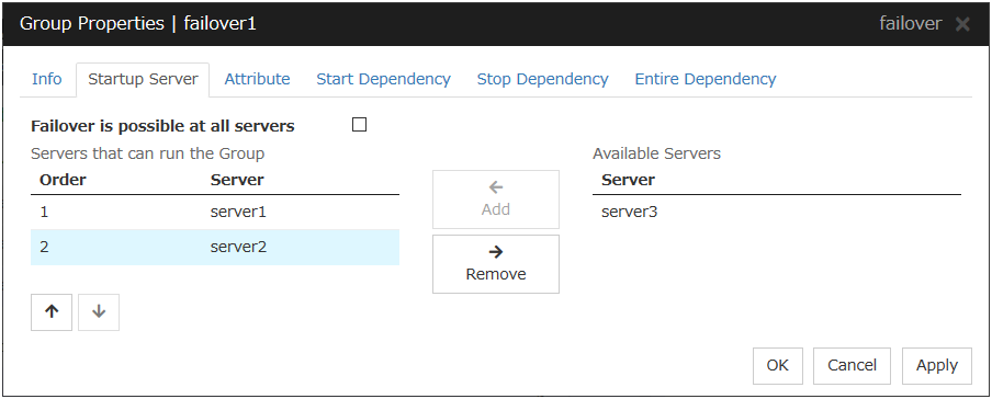
Failover is possible on all servers
Specify the server that starts a group.
Add
Use this button to add a server. Select a server that you want to add from Available Servers, and then click Add. The server is added to Servers that can run the Group.
Remove
Use this button to remove a server. Select a server that you want to remove from Servers that can run the Group, and then click Remove. The server is added to Available Servers.
Order
Use these buttons to change the priority of the servers that can be started. Select a server whose priority you want to change from Servers that can run the Group. Click the arrows to move the selected row upward or downward.
To use the server group settings:
It is necessary to configure a server group that starts up the failover group for the settings of a server that starts up a group including a hybrid disk resource.
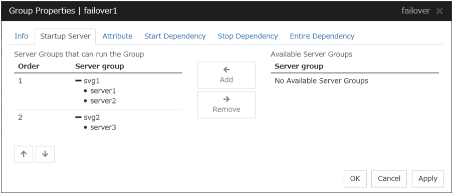
Add
Use Add to add a server group to Server Groups that can run the Group. Select a server group that you want to add from Available Server Groups, and then click Add. The selected server group is added to Server Groups that can run the Group.
Remove
Use Remove to remove a server group from Server Groups that can run the Group. Select a server group that you want to remove from Available Server Groups, and then click Remove. The server is added to Server Groups that can run the Group.
Order
Use these buttons to change the priority of a server group. Select a server group whose priority you want to change from Server Groups that can run the Group. Click the arrows to move the selected row upward or downward.
3.4.4. Attribute tab
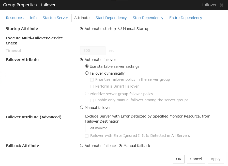
Startup Attribute
Select whether to automatically start the group from EXPRESSCLUSTER (auto startup), or to manually start from the Cluster WebUI or by using the clpgrp command (manual startup) at the cluster startup.
Execute Multi-Failover-Service Check
Check whether a double activation will occur or not before a group is started.
Timeout (1 to 9999)
Specify the maximum time to be taken to check a double activation. The default value is set as 300 seconds. Specify a larger value than the one set for Ping Timeout of Floating IP Resource Tuning Properties for the floating IP resource that belongs to the group.
Failover Attribute
Select if the failover is automatically performed when a server fails.
Failover Attribute (Advanced)
Allows an advanced configuration of the automatic failover method specified in Failover Attribute. Refer to "Understanding the group properties" for the details.
Failback Attribute
Select if the failback is executed automatically to the group when a server that has a higher priority than other server where the group is active is started. For groups that have mirror disk resources or hybrid disk resources, select manual failback.
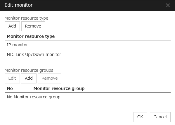
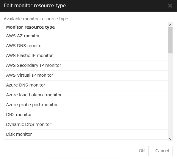
Edit Monitor
The failover process can exclude the server for which the specified monitor resource has detected an error, from the failover destinations. If Exclude server with error detected by specified monitor resource, from failover destination is selected in Failover attribute (Advanced), you can set the monitor resource that is used.
The monitor resource that is used can be set with the monitor resource type and monitor resource name.
Adds the selected monitor resource type.
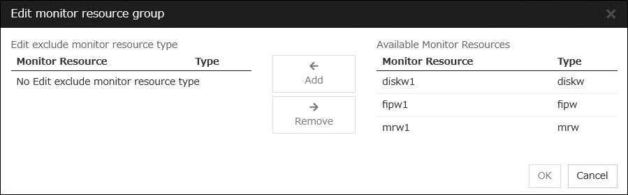
If multiple monitor resources are registered in a single monitor resource group, the server in which all the registered monitor resources are abnormal is excluded from the failover destinations.
Moreover, if multiple monitor resource groups are registered, a server that satisfies at least one of the conditions is excluded from the failover destinations.
Add
Adds the monitor resource selected from Available monitor resource list to Monitor resource list.
Remove
Removes the monitor resource selected with Monitor resource list, from the list.
Note
The following monitor resources cannot be registered for the monitor resource type. Moreover, a resource name of these resources cannot be registered for the monitor resource group.
User mode monitor
ARP monitor
Virtual IP monitor
Mirror disk connect monitor
Hybrid disk monitor
Hybrid disk connect monitor
Note
The monitor resource in the warning status is not handled as being abnormal. The exception to this is the mirror disk monitor resource.The monitor resource set for monitoring at activation does not enter the abnormal status because it does not perform monitoring for a server other than the group start server.The monitor resource stopped with the Cluster WebUI or clpmonctrl command enters the normal status.A server that has not been set to monitor a monitor resource does not enter the abnormal status because it does not perform monitoring.Note
In the case of the mirror disk monitor resource, a check is made as to whether the mirror disk resource can be activated. There is no dependence on the status of the mirror disk monitor resource.Even if the mirror disk monitor resource is in the error status, the server on which the mirror disk resource can be activated normally is not excluded from the failover destination.Even if the mirror disk monitor resource is in the normal or caution status, the server on which the mirror disk resource cannot be activated normally is excluded from the failover destination.
3.4.5. Start Dependency tab
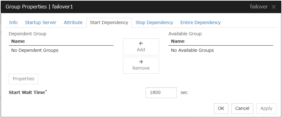
Add
Clicking Add adds the group selected from Available Group to Dependent Group.
Remove
Clicking Remove removes the group selected from Dependent Group.
Start Wait Time (0 to 9999)
Specify how many seconds you want to wait before a timeout in the target group start process. The default value is 1800 seconds.
Property
Clicking Property changes the properties of the group selected from Dependent Group.

Wait Only when on the Same Server
Specify whether you wait for start waiting only when the group which starts waiting and the target group start on the same server.
When Wait Only when on the Same Server is selected
When the server which starts the group that starts waiting isn't included in the Startup Server of a target group, you don't wait.
When a target group fails to start on a server other than the server which starts the group that starts waiting, you don't wait.
3.4.6. Stop Dependency tab
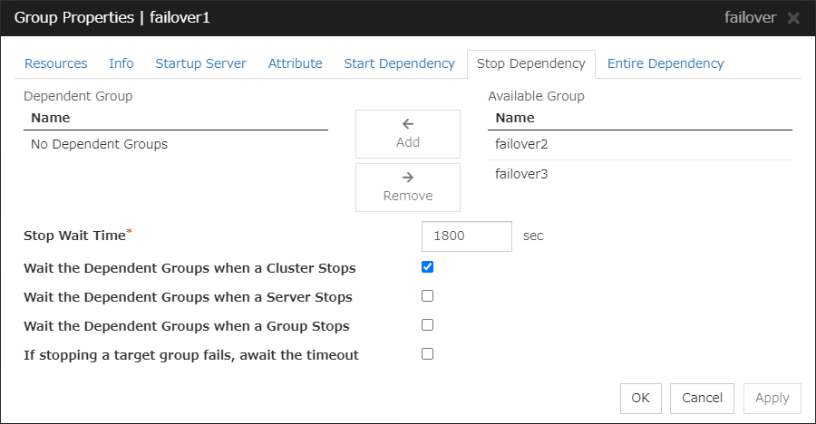
Add
Clicking Add adds the group selected from Available Group to Dependent Group.
Remove
Clicking Remove removes the group selected from Dependent Group.
Stop Wait Time (0 to 9999)
Specify how many seconds to wait before a timeout occurs in the target group stop processing. The default value is 1800 seconds.
Wait the Dependent Groups when a Cluster Stops
Specify whether to wait for the dependent groups to stop when the cluster stops.
Wait the Dependent Groups when a Server Stops
Specify whether to wait for the dependent groups to stop when a single server stops. This option waits for the stop of only those groups running on the same server, among all the dependent groups.
Wait the Dependent Groups when a Group Stops
Specify whether to wait for the dependent groups to stop when the groups are being stopped. This option waits for the stop of only those groups running on the same server, among all the dependent groups.
If stopping a target group fails, await the timeout
Specify whether to wait for the stop timeout following a stop failure of the target group.
If the checkbox is checked:
The timeout is awaited.
If the checkbox is not checked:
The timeout is not awaited; the currently selected group starts its own stop process.
3.4.7. Entire Dependency tab
Displays the settings of dependency among group resources.
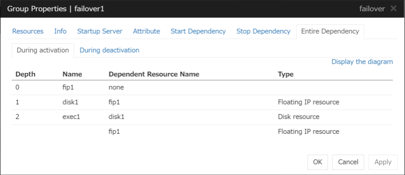
During Activation tab
Displays dependency among group resources for failover group activation.
During Deactivation tab
Displays dependency among group resources for failover group deactivation.
Display the diagram
Clicking the link displays the diagram of dependency among group resources.
3.5. Resource Properties
3.5.1. Info tab
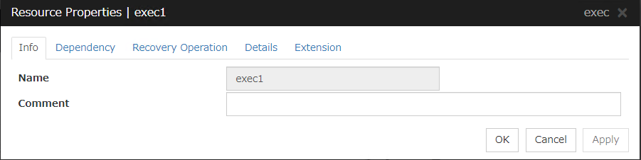
Name
The resource name is displayed.
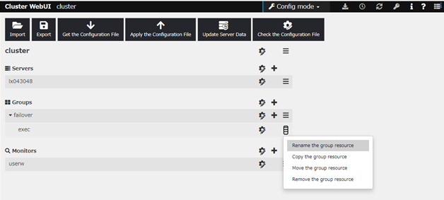
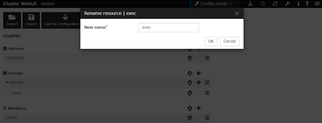
Changing the resource name
click others, and then select Rename the group resource.
A dialog box to rename resource is displayed.
Naming rules
Only alphanumeric characters, hyphen (-), underscore (_) and space are allowed for names.
Up to 31 characters (31 bytes)
Names cannot start or end with a hyphen (-) or space.
Comment (Within 127 bytes)
Enter a comment for the resource. Use only one-byte alphabets and numbers.
3.5.2. Dependency tab
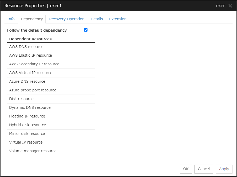
Follow the default dependence
Select if the selected group resource follows the default EXPRESSCLUSTER dependency.
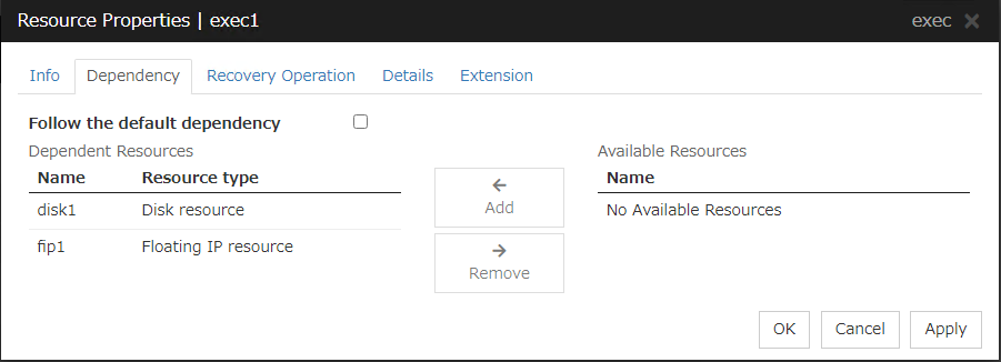
Add
It is used when adding the group resource selected in Available Resources to Dependent Resources.
Remove
It is used when removing the group resource selected in Dependent Resources from Dependent Resources.
3.5.3. Recovery Operation tab
When an error in activation of the group resource is detected
When an error is detected while activating the group resource, try activating it again.
When the activation retry count exceeds the number of times set in Retry Count at Activation Failure, failover is executed.
When the group resource cannot be activated even after executing a failover as many times as specified in Failover Threshold, the final action is taken.
When an error in deactivation of the group resource is detected
When an error is detected while deactivating the group resource, try deactivating it again.
When the deactivation retry count exceeds the number of times set in Retry Count at Deactivation Failure, the final action is taken.
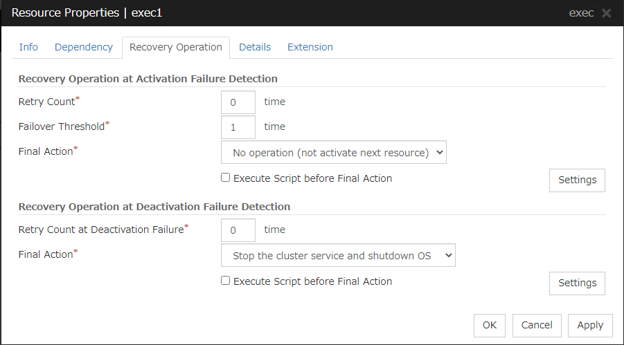
Recovery Operation at Activation Failure Detection
Retry Count at Activation Failure (0 to 99)
Enter how many times to retry activation when an activation error is detected. If this is set to zero (0), the activation will not be retried.
Failover Threshold (0 to 99)
Enter how many times to retry failover after activation retry fails as many times as the number of times set in Retry Count at Activation Failure when an error in activation is detected.If this is set to zero (0), failover will not be executed.
Final Action
Select an action to be taken when activation retry failed the number of times specified in Activation Retry Threshold and failover failed as many times as the number of times specified in Failover Threshold when an activation error is detected.
Select a final action from the following:
Note
If performing the sysrq panic fails, the OS is shut down.
Note
If resetting keepalive fails, the OS is shut down. Do not select this action on the OS and kernel where the clpkhb and clpka drivers are not supported
Note
If performing the keepalive panic fails, the OS is shut down. Do not select this action on the OS and kernel where the clpkhb and clpka drivers are not supported.
Note
If resetting BMC fails, the OS is shut down. Do not select this action on the server where OpenIPMI is not installed, or the ipmitool command does not run.
Note
If powering off BMC fails, the OS is shut down. Do not select this action on the server where OpenIPMI is not installed, or the ipmitool command does not run.
Note
If performing the power cycle of BMC fails, the OS is shut down. Do not select this action on the server where OpenIPMI is not installed, or the ipmitool command does not run.
Note
If BMC NMI fails, the OS shutdown is performed. Do not select this action on the server where OpenIPMI is not installed, or the ipmitool command does not run.
Execute Script before Final Action
Select whether script is run or not before executing final action when an activation failure is detected.
Recovery Operation at Deactivation Failure Detection
Retry Count at Deactivation Failure (0 to 99)
Enter how many times to retry deactivation when an error in deactivation is detected.
If you set this to zero (0), deactivation will not be retried.
Final Action
Select the action to be taken when deactivation retry failed the number of times specified in Retry Count at Deactivation Failure when an error in deactivation is detected.
Select the final action from the following:
Note
If No Operation is selected as the final action when a deactivation error is detected, group does not stop but remains in the deactivation error status.Make sure not to set No Operation in the production environment.Note
If No Operation is selected as the final action when a deactivation error is detected, group does not stop but remains in the deactivation error status.Make sure not to set No Operation in the production environment.Note
If performing the sysrq panic fails, the OS is shut down.
Note
If resetting keepalive fails, the OS is shut down. Do not select this action on the OS and kernel where the clpkhb and clpka drivers are not supported
Note
If performing the keepalive panic fails, the OS is shut down. Do not select this action on the OS and kernel where the clpkhb and clpka drivers are not supported.
Note
If resetting BMC fails, the OS is shut down. Do not select this action on the server where OpenIPMI is not installed, or the ipmitool command does not run.
Note
If powering off BMC fails, the OS is shut down. Do not select this action on the server where OpenIPMI is not installed, or the ipmitool command does not run.
Note
If performing the power cycle of BMC fails, the OS is shut down. Do not select this action on the server where OpenIPMI is not installed, or the ipmitool command does not run.
Note
If BMC NMI fails, the OS shutdown is shut down. Do not select this action on the server where OpenIPMI is not installed, or the ipmitool command does not run.
Execute Script before Final Action
Select whether script is run or not before executing final action when a deactivation failure is detected.
3.5.4. Details tab
The parameters specific to each resource are described in its explanation part.
3.5.5. Extension tab
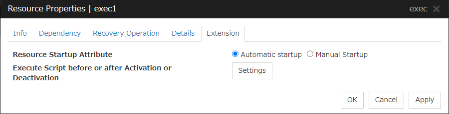
Resource Startup Attribute
Select whether to automatically start up the resource in starting up the group or manually (by using Cluster WebUI or the clprsc command).
Execute Script before or after Activation or Deactivation
Select whether script is running or not before and after activation/deactivation of group resources. To configure the script settings, click Script Settings.
The script can be run at the specified timing by selecting the checkbox.
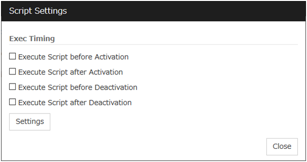
Exec Timing
Execute Script before Activation
Execute Script after Activation
Execute Script before Deactivation
Execute Script after Deactivation
To configure the script settings, click Script Settings.
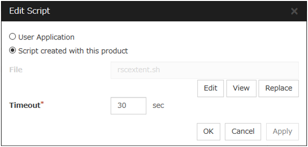
User Application
Use an executable file (executable shell script file or execution file) on the server as a script. For the file name, specify an absolute path of the local disk on the server. If there is any blank in the absolute path or the file name, put them in double quotation marks ("") as follows.
Example:
"/tmp/user application/script.sh"
Each executable files is not included in the cluster configuration information of the Cluster WebUI. They must be prepared on each server because they cannot be edited nor uploaded by the Cluster WebUI.
Script created with this product
Use a script file which is prepared by the Cluster WebUI as a script. You can edit the script file with the Cluster WebUI if you need. The script file is included in the cluster configuration information.
File (Within 1023 bytes)
Specify a script to be executed (executable shell script file or execution file) when you select User Application.
View
Click here to display the script file when you select Script created with this product.
Edit
Click here to edit the script file when you select Script created with this product. Click Save to apply the change. You cannot modify the name of the script file.
Replace
Click here to replace the contents of a script file with the contents of the script file which you selected in the file selection dialog box when you select Script created with this product. You cannot replace the script file if it is currently displayed or edited. Select a script file only. Do not select binary files (applications), and so on.
Timeout (1 to 9999)
Specify the maximum time to wait for completion of script to be executed.The default value of the time taken to execute script before and after activation/deactivation is 30 seconds.The default value of the timeout settable from Settings button of Execute Script before Final Action for Recovery Operation at Activation Failure Detection or Recovery Operation at Deactivation Failure Detection is 5 seconds.
3.6. Understanding EXEC resources
You can register applications and shell scripts that are managed by EXPRESSCLUSTER and to be run when starting, stopping, failing over or moving groups in EXPRESSCLUSTER. It is also possible to register your own programs and shell scripts in EXEC resources. You can write codes as required for respective application because shell scripts are in the same format as an sh shell script.
Note
The same version of the application to be run from EXEC resources must be installed on all servers in failover policy.
3.6.1. Dependency of EXEC resources
By default, exec resources depend on the following group resource types:
Group resource type |
|---|
Floating IP resource |
Virtual IP resource |
Disk resource |
Mirror disk resource |
Hybrid disk resource |
Volume manager resource |
Dynamic DNS resource |
AWS elastic ip resource |
AWS virtual ip resource |
AWS secondary ip resource |
AWS DNS resource |
Azure probe port resource |
Azure DNS resource |
3.6.2. Method of judging EXEC resource activation/deactivation results
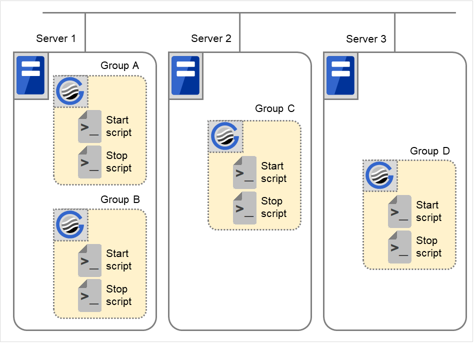
3.6.3. Scripts in EXEC resources
Types of scripts
Start script and stop script are provided in EXEC resources. EXPRESSCLUSTER runs a script for each EXEC resource when the cluster needs to change its status. You have to write procedures in these scripts about how you want applications to be started, stopped, and restored in your cluster environment.
3.6.4. Environment variables in EXEC resource script
When EXPRESSCLUSTER runs a script, it records information such as condition when the scrip was run (script starting factor) in environment variables.
You can use the environment variables in the table below as branching condition when you write codes for your system operation.
Stop script returns the contents of the previous start script in the environment variable as a value. Start script does not set environment variables of CLP_FACTOR and CLP_PID.
The environment variable CLP_LASTACTION is set only when the environment variable CLP_FACTOR is CLUSTERSHUTDOWN or SERVERSHUTDOWN.
Environment Variable |
Value of environment variable |
Meaning |
|---|---|---|
CLP_EVENT
...script starting factor
|
START |
The script was run:
|
FAILOVER |
The script was run on the failover target server:
|
|
CLP_FACTOR
...group stopping factor
|
CLUSTERSHUTDOWN |
The group was stopped by stopping the cluster. |
SERVERSHUTDOWN |
The group was stopped by stopping the server. |
|
GROUPSTOP |
The group was stopped by stopping the group. |
|
GROUPMOVE |
The group was moved by moving the group. |
|
GROUPFAILOVER |
The group failed over because an error was detected in monitor resource; or
the group failed over because of activation failure in group resources.
|
|
GROUPRESTART |
The group was restarted because an error was detected in monitor resource. |
|
RESOURCERESTART |
The group resource was restarted because an error was detected in monitor resource. |
|
CLP_LASTACTION
...process after cluster
shutdown
|
REBOOT |
In case of rebooting OS |
HALT |
In case of halting OS |
|
NONE |
No action was taken. |
|
CLP_SERVER
...server where the script was run
|
HOME |
The script was run on the primary server of the group. |
OTHER |
The script was run on a server other than the primary server of the group. |
|
SUCCESS |
There was no partition where connection had failed. |
|
FAILURE |
There was one or more partition where connection had failed. |
|
CLP_PRIORITY
... the order in failover
policy of the server
where the script is run
|
1 to the number of servers in the cluster |
Represents the priority of the server where the script is run. This number starts from 1 (The smaller the number, the higher the server's priority).
If CLP_PRIORITY is 1, it means that the script is run on the primary server.
|
CLP_GROUPNAME
...Group name
|
Group name |
Represents the name of the group to which the script belongs. |
CLP_RESOURCENAME
...Resource name
|
Resource name |
Represents the name of the resource to which the script belongs. |
CLP_PID
...Process ID
|
Process ID |
Represents the process ID of start script when the property of start script is set to asynchronous. This environment variable is null when the start script is set to synchronous. |
CLP_VERSION_FULL
...EXPRESSCLUSTER
full version
|
EXPRESSCLUSTER full version |
Represents the EXPRESSCLUSTER full version.
(Example) 5.2.1-1
|
CLP_VERSION_MAJOR
...EXPRESSCLUSTER
major version
|
EXPRESSCLUSTER major version |
Represents the EXPRESSCLUSTER major version.
(Example) 5
|
CLP_PATH
...EXPRESSCLUSTER
installation path
|
EXPRESSCLUSTER install path |
Represents the path where EXPRESSCLUSTER is installed.
(Example) /opt/nec/clusterpro
|
CLP_OSNAME
...Server OS name
|
Server OS name |
Represents the OS name of the server where the script was executed.
(Example)
1. When the OS name could be acquired:
Red Hat Enterprise Linux Server release 6.8 (Santiago)
2. When the OS name could not be acquired:
Linux
|
CLP_OSVER
...Server OS version
|
Server OS version |
Represents the OS version of the server where the script was executed.
(Example)
1. When the OS version could be acquired: 6.8
2. When the OS version could not be acquired: Blank
|
- 1
Applicable to disk resources, mirror disk resources, hybrid resources, and volume manager resources.
Environment variable |
Value of environment variable |
Meaning |
|---|---|---|
CLP_EVENT
...script starting factor
|
STANDBY |
The script was run on the standby server.
|
CLP_SERVER
...server where the script was run
|
HOME |
The script was run on the primary server of the group. |
OTHER |
The script was run on a server other than the primary server of the group. |
|
CLP_PRIORITY
... the order in failover
policy of the server
where the script is run
|
1 to the number of servers in the cluster |
Represents the priority of the server where the script is run. This number starts from 1 (The smaller the number, the higher the server's priority).
If CLP_PRIORITY is 1, it means that the script is run on the primary server.
|
CLP_GROUPNAME
...Group name
|
Group name |
Represents the name of the group to which the script belongs. |
CLP_RESOURCENAME
...Resource name
|
Resource name |
Represents the name of the resource to which the script belongs. |
CLP_VERSION_FULL
...Full version of EXPRESSCLUSTER
|
Full version of EXPRESSCLUSTER |
Represents the full version of EXPRESSCLUSTER (e.g. 5.2.1-1 ). |
CLP_VERSION_MAJOR
...Major version of EXPRESSCLUSTER
|
Major version of EXPRESSCLUSTER |
Represents the major version of EXPRESSCLUSTER (e.g. 5). |
CLP_PATH
...EXPRESSCLUSTER installation path
|
EXPRESSCLUSTER installation path |
Represents the EXPRESSCLUSTER installation path (e.g. /opt/nec/clusterpro). |
CLP_OSNAME
...Server OS name
|
Server OS name |
Represents the OS name of the server where the script was executed.
(Example)
1. When the OS name was acquired:
Red Hat Enterprise Linux Server release 6.8 (Santiago)
2. When the OS name was not acquired:
Linux
|
CLP_OSVER
...Server OS version
|
Server OS version |
Represents the OS version of the server where the script was executed.
(Example)
1. When the OS version was acquired: 6.8
2. When the OS version was not acquired: Blank
|
3.6.5. Execution timing of EXEC resource script
This section describes the relationships between the execution timings of start and stop scripts and environment variables according to cluster status transition diagram.
To simplify the explanations, 2-server cluster configuration is used as an example. See the supplements for the relations between possible execution timings and environment variables in 3 or more server configurations.
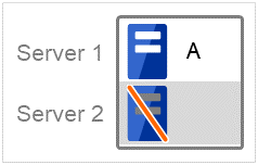
In the diagram, servers illustrates the following statuses:
Server
Server status

Normal (properly working as a cluster)

Stopped (cluster is stopped)
(Example) Group A is working on a normally running server.
Each group is started on the top priority server among active servers.
Three Group A, B and C are defined in the cluster, and they have their own failover policies as follows:
Group |
1st priority server |
2nd priority server |
|---|---|---|
A |
Server 1 |
Server 2 |
B |
Server 2 |
Server 1 |
C |
Server 1 |
Server 2 |
<Cluster status transition diagram>
This diagram illustrates a typical status transition of cluster.
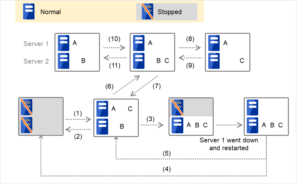
Fig. 3.36 Example of cluster status transition: overview
Numbers 1. to 11. in the diagram correspond to descriptions as follows.
Normal startup
Normal startup here means that the start script has been run properly on the primary server.
Each group is started on the server with the highest priority among the active servers.
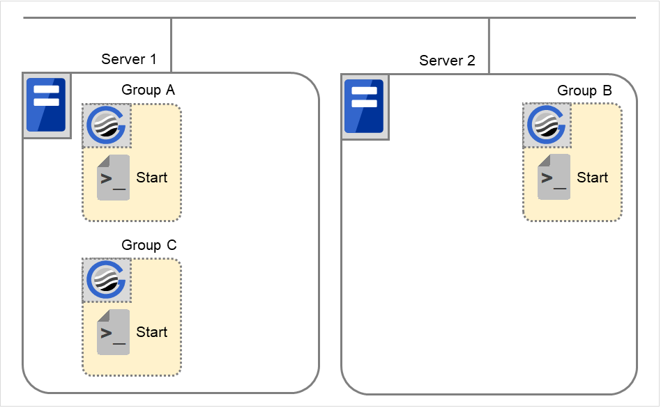
Fig. 3.37 Situation and script execution: normal startup
Environment variables for Start
Group A
Group B
Group C
CLP_EVENT
START
START
START
CLP_SERVER
HOME
HOME
HOME
Normal shutdown
Normal shutdown here means a cluster shutdown immediately after the start script corresponding to the stop script that was run by performing normal startup or by moving a group (online failback).
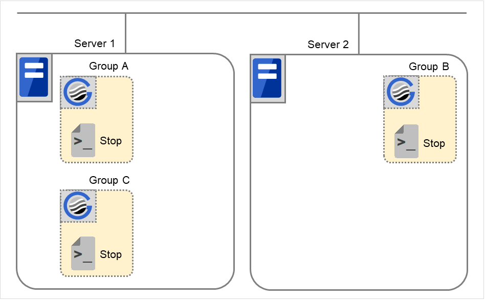
Fig. 3.38 Situation and script execution: normal shutdown
Environment variables for Stop
Group A
Group B
Group C
CLP_EVENT
START
START
START
CLP_SERVER
HOME
HOME
HOME
Failover at Server 1 down
When the start scrip of a group which has Server 1 as its primary server, it is run on a lower priority server (Server 2) when an error occurs. You need to write CLP_EVENT(=FAILOVER) as a branching condition for triggering application startup and recovery processes (such as database rollback process) in the start script in advance.
For the process to be performed only on a server other than the primary server, specify CLP_SERVER(=OTHER) as a branching condition and describe the process in the script.
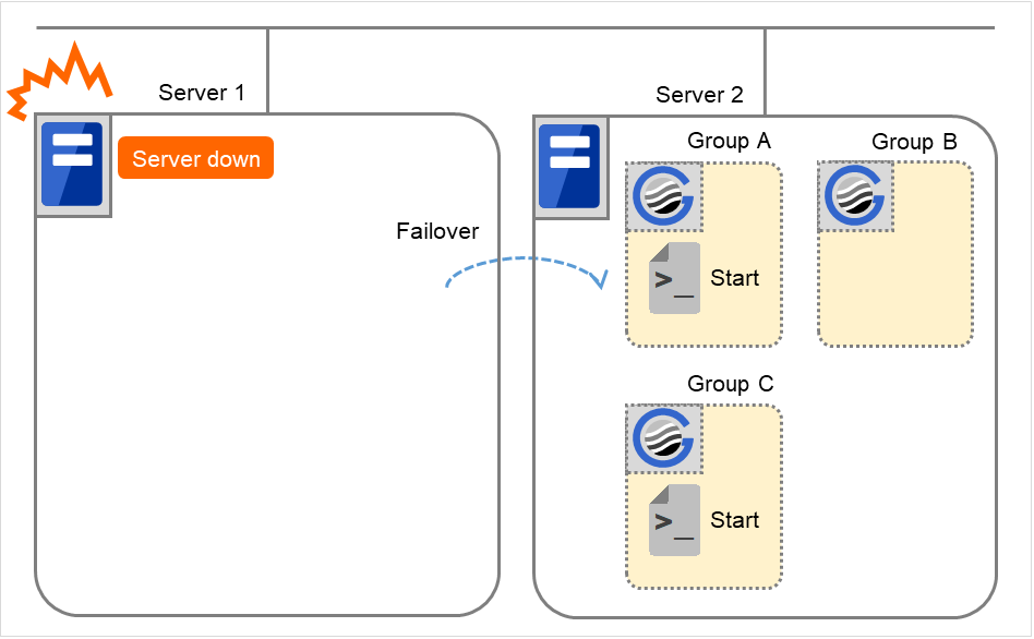
Fig. 3.39 Situation and script execution: failover due to server down
Environment variables for Start
Group A
Group C
CLP_EVENT
FAILOVER
FAILOVER
CLP_SERVER
OTHER
OTHER
Cluster shutdown after failover of Server 1
The stop scripts of the Group A and C are run on Server 2 where the groups fail over (the stop script of Group B is run by a normal shutdown).
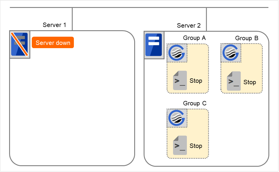
Fig. 3.40 Situation and script execution: cluster shutdown after failover
Environment variables for Stop
Group A
Group B
Group C
CLP_EVENT
FAILOVER
START
FAILOVER
CLP_SERVER
OTHER
HOME
OTHER
Moving of Group A and C
After the stop scripts of Group A and C are run on Server 2 where the groups fail over, their start scripts are run on Server 1.
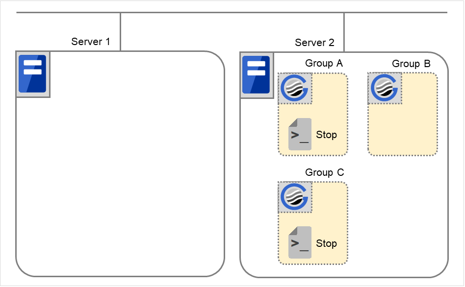
Fig. 3.41 Situation and script execution: moving Groups A and C (1)
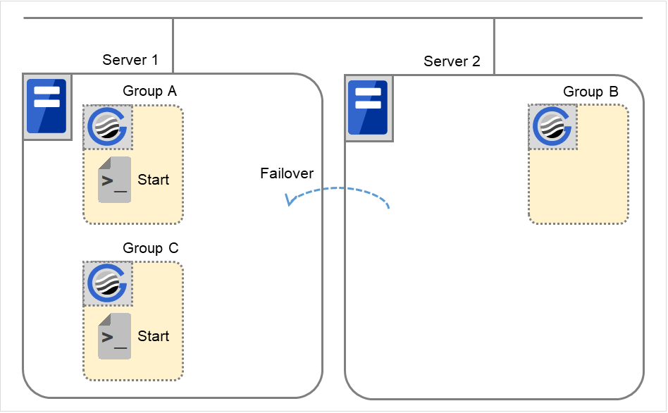
Fig. 3.42 Situation and script execution: moving Groups A and C (2)
Environment variables for Stop
Group A
Group C
CLP_EVENT
FAILOVER 2
FAILOVER
CLP_SERVER
OTHER
OTHER
Environment variables for Start
Group A
Group C
CLP_EVENT
START
START
CLP_SERVER
HOME
HOME
- 2
- Environment variables in a stop script take those in the previous start script.For moving in "5. Moving of Group A and C" because it is not preceded by a cluster shutdown, the environment variable used here is FAILOVER. However, if a cluster shutdown is executed before moving in "5. Moving of Group A and C," the environment variable is START.
Error in Group C and failover
When an error occurs in Group C, its stop script is run on Server 1 and start script is run on Server 2.
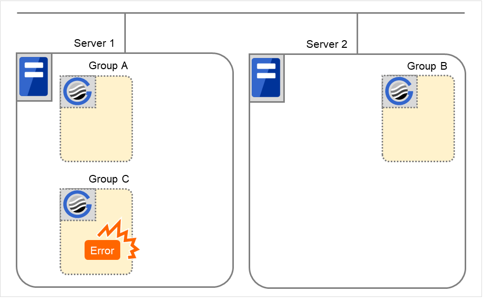
Fig. 3.43 Situation and script execution: error in Group C and failover (1)
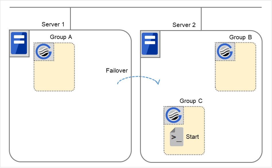
Fig. 3.44 Situation and script execution: error in Group C and failover (2)
Environment variables for Stop of Server 1
Group C
CLP_EVENT
START
CLP_SERVER
HOME
Environment variables for Start of Server 2
Group C
CLP_EVENT
FAILOVER
CLP_SERVER
OTHER
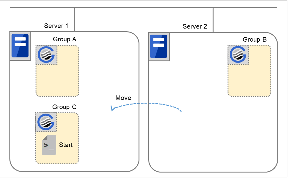
Moving of Group C
Move the Group C that is failed over to Server 2 in 6. from Server 2 to Server 1. Run the stop script on Server 2, and then run the start script on Server 1.
Stopping Group B
The stop script of Group B is run on Server 2.

Fig. 3.47 Situation and script execution: stopping Group B
Stop
Group B
CLP_EVENT
START
CLP_SERVER
HOME
Starting Group B
The start script of Group B is run on Server 2.
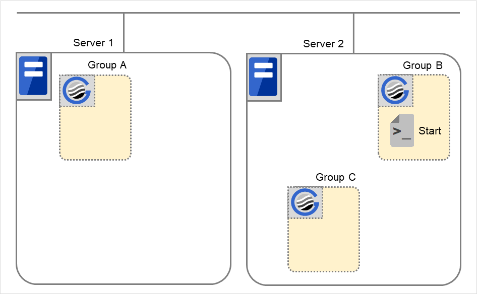
Fig. 3.48 Situation and script execution: starting Group B
Start
Group B
CLP_EVENT
START
CLP_SERVER
HOME
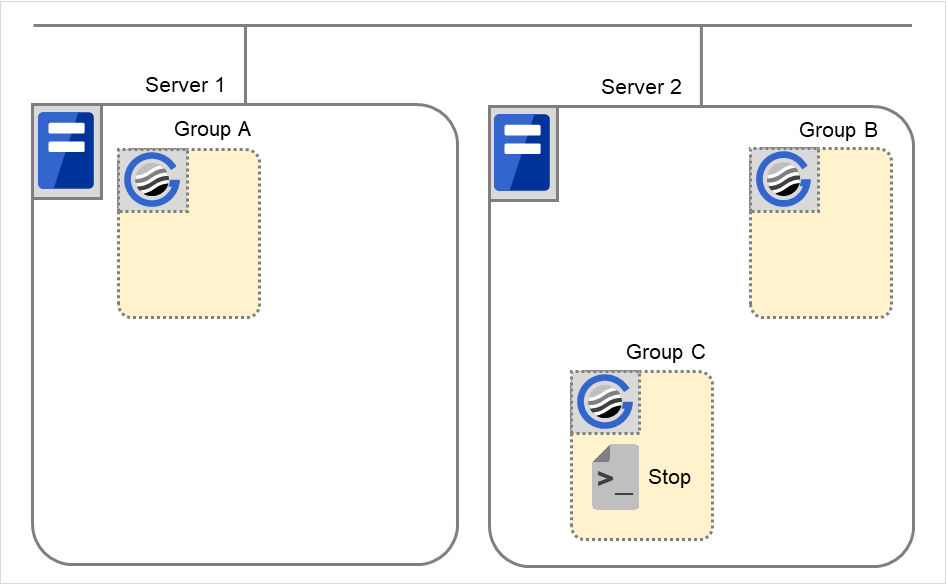
Stopping Group C
The stop script of Group C is run on Server 2.

Fig. 3.49 Situation and script execution: stopping Group C
Stop
Group C
CLP_EVENT
FAILOVER
CLP_SERVER
OTHER
Starting Group C
The start scrip of Group C is run on Server 2.

Fig. 3.50 Situation and script execution: starting Group C
Start
Group C
CLP_EVENT
START
CLP_SERVER
OTHER
Supplementary information 1
For a group that has three or more servers specified in the failover policy to behave differently on servers other than the primary server, use CLP_PRIORITY instead of CLP_SERVER(HOME/OTHER).
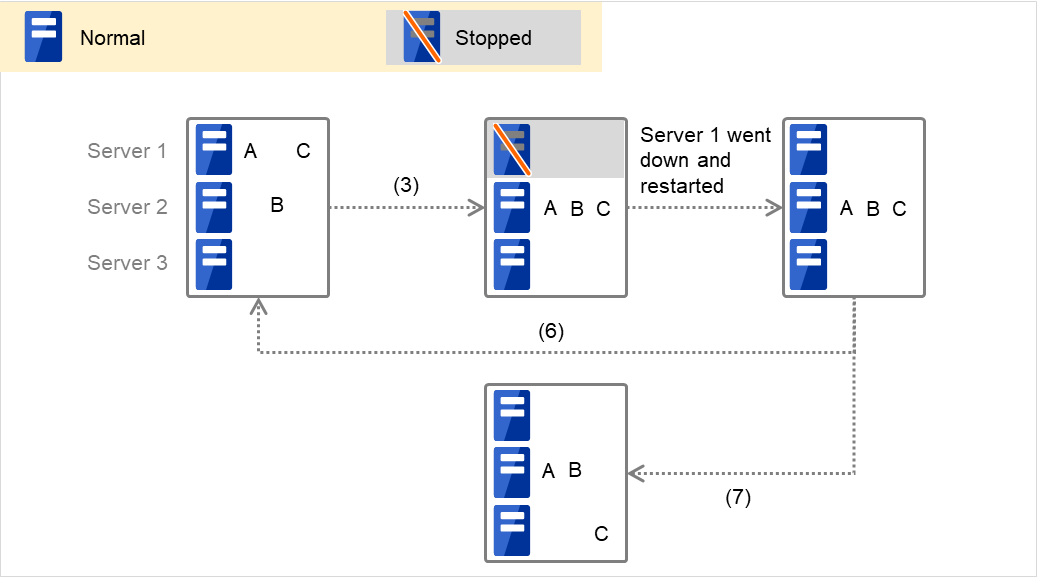
Fig. 3.51 Example of cluster status transition: failover due to server down
Example 1: "3. Failover at Server 1 down" in the cluster status transition diagram
A group has Server 1 as its primary server. If an error occurs on Server 1, its start script is run on Server 2 that has next highest priority failover policy. You need to write CLP_EVENT(=FAILOVER) as the branching condition for triggering applications' startup and recovery processes (such as database rollback process) in the start script in advance.
For a process to be performed only on the server that has the second highest priority failover policy, it is necessary to write CLP_PRIORITY(=2) as the branching condition.
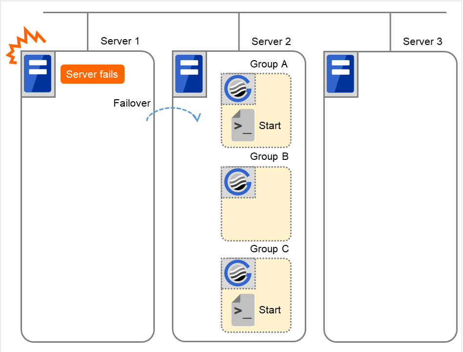
Fig. 3.52 Situation and script execution: starting Groups A and C
Environment variables for Start
Group A
Group C
CLP_EVENT
FAILOVER
FAILOVER
CLP_SERVER
OTHER
OTHER
CLP_PRIORITY
2
2
Example 2: "7. Moving of Group C" in the cluster status transition diagram

Fig. 3.53 Example of cluster status transition: moving Group C
After the stop script of Group C is run on Server 2 where the group failed over from, the start script is run on Server 3.
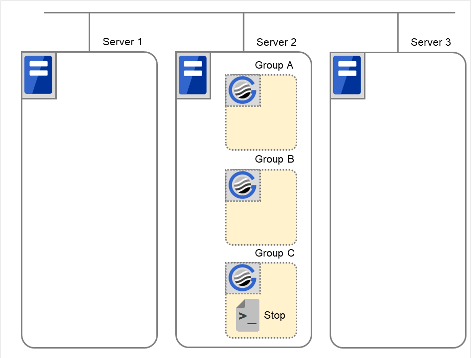
Fig. 3.54 Situation and script execution: moving Group C (1)
Environment variables for Stop
Group C
CLP_EVENT
FAILOVER
CLP_SERVER
OTHER
CLP_PRIORITY
2
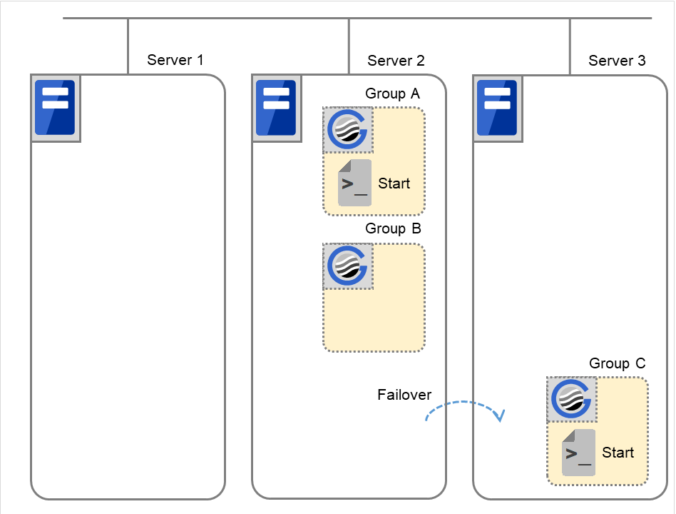
Fig. 3.55 Situation and script execution: moving Group C (2)
Environment variables for Start
Group C
CLP_EVENT
START
CLP_SERVER
OTHER
CLP_PRIORITY
3
Supplementary information 2
When monitor resource starts or restarts a script:
To run the start script when resource monitor detected an error in application, the environment variables should be as follows:
Example 1: Resource monitor detects abnormal termination of an application that was running on Server 1 and restarts Group A on the Server 1.

Fig. 3.56 Situation and script execution: restarting Group A (1)
Environment variable for Stop
Group A |
|
|---|---|
CLP_EVENT |
The same value as when the start script is run |
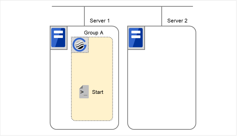
Fig. 3.57 Situation and script execution: restarting Group A (2)
Environment variable for Start
Group A
CLP_EVENT
START
Example2: Resource monitor detects abnormal termination of an application that was running on Server 1, fails over to Server 2 and restarts Group A on Server 2
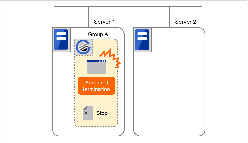
Fig. 3.58 Situation and script execution: failover of Group A (1)
Environment variable for Stop
Group A |
|
|---|---|
CLP_EVENT |
The same value as when the start script is run |
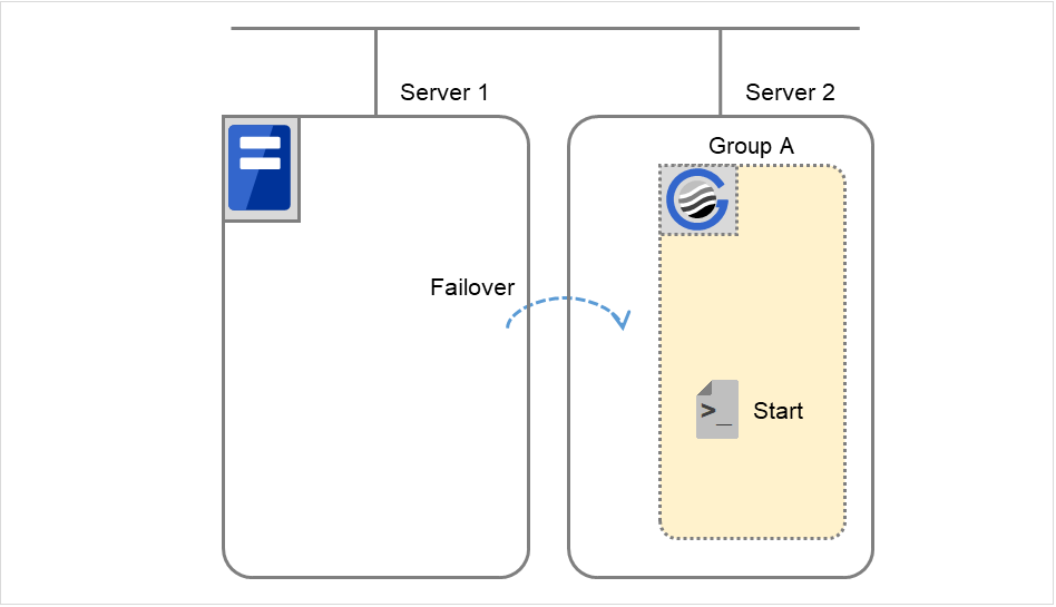
Fig. 3.59 Situation and script execution: failover of Group A (2)
Environment variable for Start
Group A |
|
|---|---|
CLP_EVENT |
FAILOVER |
Supplementary information 3
With Execute on standby server of Exec Resource Tuning Properties enabled, start and stop scripts can also be executed on another server (standby server) that does not start a group--in accordance with the timings of running these scripts on the active server that started a group.
Compared with the script execution on the active server, that on the standby server has the following characteristics:
The results (error codes) of executing the scripts do not affect the group-resource statuses.
No script before and after activation/deactivation is executed.
Monitor resources set for monitoring at activation are not started or stopped.
Different types and values of environment variables are set. (Refer to "Environment variables in EXEC resource script" as described above.)
No failover is performed for the cluster service stopped on the active server.
The following describes the relationships between the execution timings of scripts on the standby server and the environment variables--with cluster status transition diagrams.
<Cluster status transition diagram>
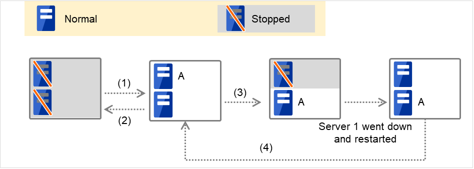
Fig. 3.60 Example of cluster status transition: failover due to server down
Numbers 1. to 4. in the diagram correspond to the following descriptions:
Normal startup
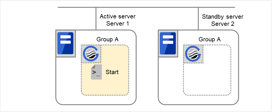
Fig. 3.61 Situation and script execution: normal startup of Group A (1)
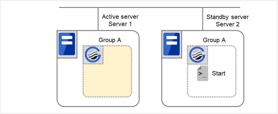
Fig. 3.62 Situation and script execution: normal startup of Group A (2)
Environment variables for Start
Server 1
Server 2
CLP_EVENT
START
STANDBY
CLP_SERVER
HOME
OTHER
Normal shutdown
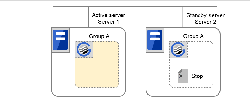
Fig. 3.63 Situation and script execution: normal shutdown of Group A (1)
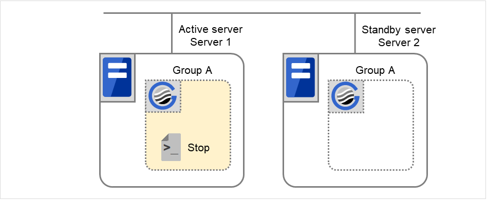
Fig. 3.64 Situation and script execution: normal shutdown of Group A (2)
Environment variables for Stop
Server 1
Server 2
CLP_EVENT
START
STANDBY
CLP_SERVER
HOME
OTHER
Failover at Server 1 down
With Server 1 crashed, the start script is not run on it as the standby server.
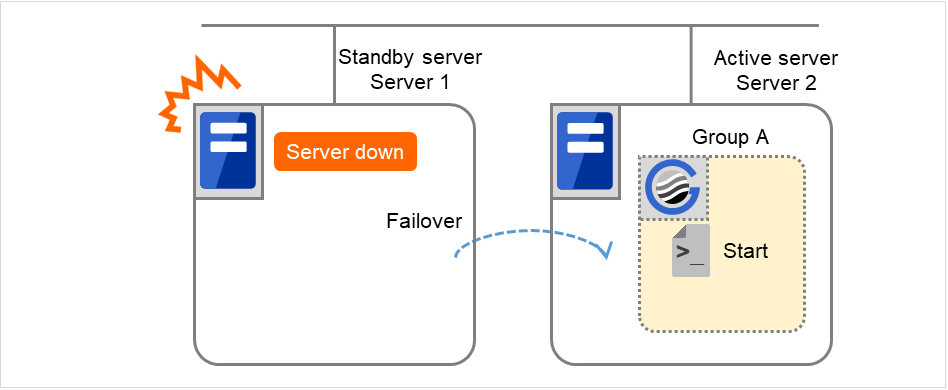
Fig. 3.65 Example of cluster status transition: failover due to server down
Environment variables for Start
Server 2
CLP_EVENT
FAILOVER
CLP_SERVER
OTHER
Moving of Group A
The stop script for Group A is executed on Server 1 (= standby server) and Server 2 (= active server). Then the start script is run on Server 1 (= active server) and Server 2 (= standby server).
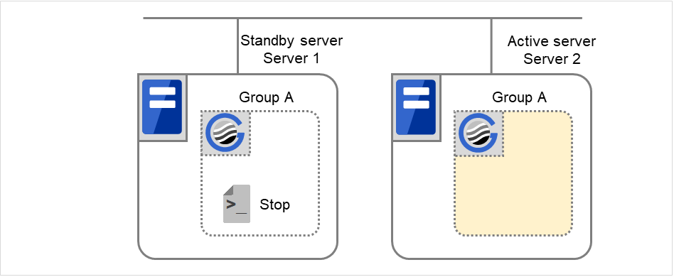
Fig. 3.66 Situation and script execution: moving Group A (1)
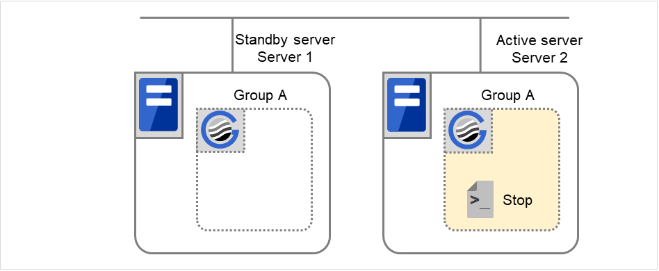
Fig. 3.67 Situation and script execution: moving Group A (2)
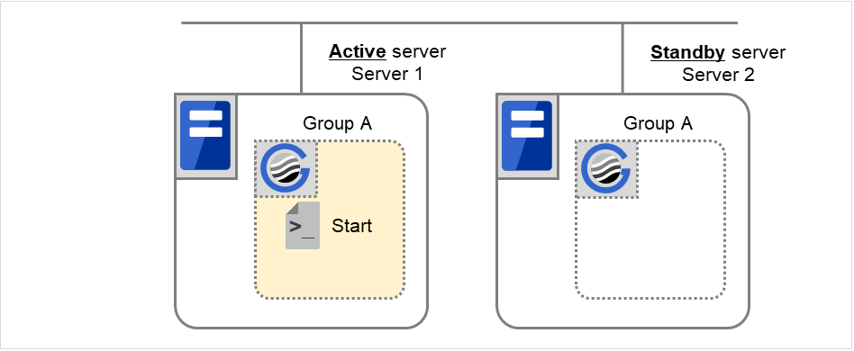
Fig. 3.68 Situation and script execution: moving Group A (3)
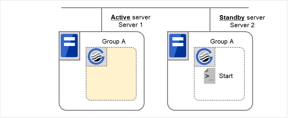
Fig. 3.69 Situation and script execution: moving Group A (4)
Environment variables for Stop
Server 1
Server 2
CLP_EVENT
STANDBY
FAILOVER 3
CLP_SERVER
HOME
OTHER
- 3
Environment variables for Start
Server 1
Server 2
CLP_EVENT
START
STANDBY
CLP_SERVER
HOME
OTHER
3.6.6. Writing EXEC resource scripts
This section explains timing script execution described in the preceding topic relating to the actual script codes.
Numbers in brackets "(number)" in the following example script code represent the actions described in " Execution timing of EXEC resource script ".
Group A start script: A sample of start.sh
#!/bin/sh
# ***************************************
# *              start.sh               *
# ***************************************

# Refer to the environment variable of the script execution factor to determine the subsequent process.
if [ "$CLP_EVENT" = "START" ]
then
    # Refer to the environment variable of DISK connection information to determine whether error handling is necessary.
    if [ "$CLP_DISK" = "SUCCESS" ]
    then
        # Here, write the normal startup process of the operation.
        # This process is to be performed at the timing of the following:
        #
        # (1) Normal startup
        # (5) Moving of Groups A and C
        #

        # Refer to the environment variable of the execution server to determine the subsequent process.
        if [ "$CLP_SERVER" = "HOME" ]
        then
            # Here, write a process to be performed only for the normal startup of the operation on the primary server.
            # This process is to be performed at the timing of the following:
            #
            # (1) Normal startup
            # (5) Moving of Groups A and C
            #

        else
            # Here, write a process to be performed only for the normal startup of the operation on a non-primary server.
            #
        fi
    else
        # Here, write a disk-related error-handling process.
        #

    fi
elif [ "$CLP_EVENT" = "FAILOVER" ]
then

    # Refer to the environment variable of DISK connection information to determine whether error handling is necessary.
    if [ "$CLP_DISK" = "SUCCESS" ]
    then
        # Here, write the normal startup process of the operation.
        # This process is to be performed at the timing of the following:
        #
        # (3) Failover at Server 1 down
        #

        # Refer to the environment variable of the execution server to determine the subsequent process.
        if [ "$CLP_SERVER" = "HOME" ]
        then
            # Here, write a process to be performed only for the startup of the operation on the primary server after the failover.
            #

        else
            # Here, write a process to be performed only for the startup of the operation on a non-primary server after the failover.
            # This process is to be performed at the timing of the following:
            #
            # (3) Failover at Server 1 down
            #

        fi
    else
        # Here, write a disk-related error-handling process.
        #

    fi
else
    # EXPRESSCLUSTER is not working.

fi

# If the end code  is zero (0), the EXEC resource activation is judged to be successful.
# Write to make a non-zero end code returned in response to an error in the script.
exit 0
Group A stop script: A sample of stop.sh
#!/bin/sh
# ***************************************
# *              stop.sh               *
# ***************************************

# Refer to the environment variable of the script execution factor to determine the subsequent process.
if [ "$CLP_EVENT" = "START" ]
then
    if [ "$CLP_DISK" = "SUCCESS" ]
    then
        # Here, write the normal end process of the operation. This process is to be performed at the timing of the following:
        #
        # (2) Normal shutdown
        #

        # Refer to the environment variable of the execution server to determine the subsequent process.
        if [ "$CLP_SERVER" = "HOME" ]
        then
            # Here, write a process to be performed only for the normal end of the operation on the primary server.
            # This process is to be performed at the timing of the following:
            #
            # (2) Normal shutdown
            #

        else
            # Here, write a process to be performed only for the normal end of the operation on a non-primary server.
            #

        fi
    else
        # Here, write a disk-related error-handling process.
        #

    fi
elif [ "$CLP_EVENT" = "FAILOVER" ]
then

    # Refer to the environment variable of DISK connection information to determine whether error handling is necessary.
    if [ "$CLP_DISK" = "SUCCESS" ]
    then
        # Here, write the normal end process to be performed after the failover.
        # This process is to be performed at the timing of the following:
        #
        # (4) Cluster shutdown after failover of Server 1
        # (5) Moving of Groups A and C
        #

        # Refer to the environment variable of the execution server to determine the subsequent process.
        if [ "$CLP_SERVER" = "HOME" ]
        then
            # Here, write a process to be performed only for the end of the operation on the primary server after the failover.
            #

        else
            # Here, write a process to be performed only for the end of the operation on a non-primary server after the failover.
            # This process is to be performed at the timing of the following:
            #
            # (4) Cluster shutdown after failover of Server 1
            # (5) Moving of Groups A and C
            #

        fi
    else
        # Here, write a disk-related error-handling process.
        #

    fi
else
    # EXPRESSCLUSTER is not working.
fi

# If the end code is zero (0), the EXEC resource deactivation is judged to be successful.
# Write to make a non-zero end code returned in response to an error in the script.
exit 0
3.6.7. Tips for creating EXEC resource script
If your script has a command that requires some time to complete, it is recommended to configure command completion messages to be always produced. This message can be used to determine the error when a problem occurs. There are two ways to produce the message:
- Specify the log output path of EXEC resource by writing the echo command in the script.The message can be produced with the echo command. Specify the log output path in the resource properties that contain the script.The message is not logged by default. For how to configure the settings for the log output path, see"Maintenance tab" in "Details tab - Tuning Properties" . If the Rotate Log check box is not selected, pay attention to the available disk space of a file system because messages are sent to the file specified as the log output destination file regardless of the size of available disk space.
(Example: sample script)
echo "appstart.."
appstart
echo "OK"
- Write the clplogcmd command in the script.The message can be produced to the Alert logs of the Cluster WebUI or syslog in OS with the clplogcmd command. For details on the clplogcmd command, see "Outputting messages (clplogcmd command)" in "9. EXPRESSCLUSTER command reference" in this guide.
(Example: sample script)
clplogcmd -m "appstart.."
appstart
clplogcmd -m "OK"
3.6.8. Notes on EXEC Resource
Script Log Rotate
When the Script Log Rotate function is enabled, a process is generated to mediate the log output. This intermediate process continues to work until the file descriptor is closed (i.e. until all the logs stop being output from the start and stop scripts and from a descendant process that takes over the standard output and/or the standard error output from the start and stop scripts). To exclude output from the descendant process from the log, redirect the standard output and/or the standard error output when the process is generated with the script.
The start script and the stop script are executed by the root user.
To start an application dependent on an environment variable, the script must set the environment variable as needed.
3.6.9. Details tab
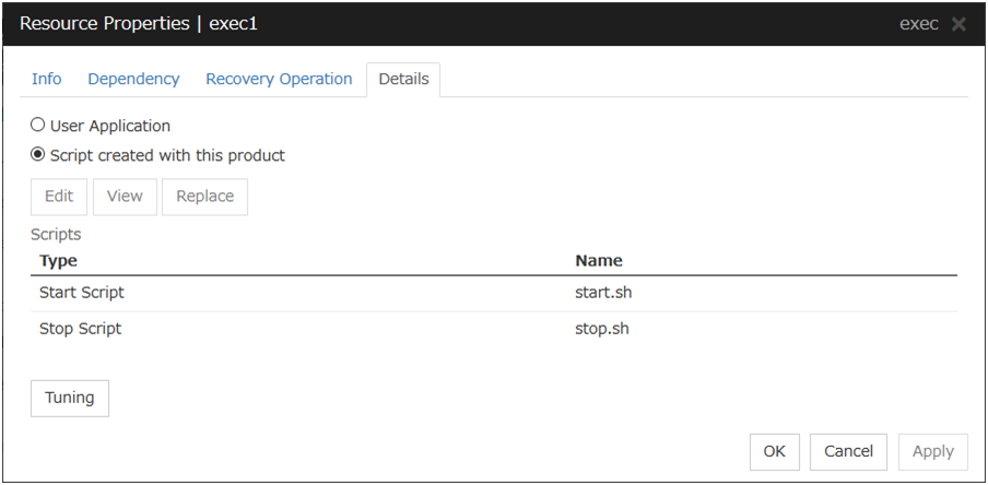
User Application
Select this option to use executable files (executable shell scripts and binary files) on your server as scripts. Specify the local disk path on the server for each executable file name.
The executable files will not be distributed to each server. They should be placed on each server in advance. The cluster configuration data created by the Cluster WebUI does not contain these files. You cannot edit the script files using the Cluster WebUI.
Script created with this product
Select this option to use script files created by the Cluster WebUI as scripts. You can edit them using the Cluster WebUI as necessary. The cluster configuration data contains these script files.
View
Click here to display the script file when you select Script created with this product.
Edit
Click here to edit the script file when you select Script created with this product. Click Save to apply changes. You cannot rename the script file
With the User Application option selected, the Enter application path dialog box appears.
Enter application path
Specify an exec resource executable file name.

Start (Within 1023 bytes)
Enter an executable file name to be run when the exec resource starts. The name should begin with "/." Arguments can also be specified.
Stop (Within 1023 bytes)
Enter an executable file name to be run when the exec resource exits. The name should begin with "/." The stop script is optional.
For the executable file name, specify a full path name starting with "/" to a file on your cluster server.
Arguments can also be specified.
Replace
Opens the Open dialog box with the Script created with this product option selected.
The contents of the script file selected in the Resource Properties are replaced with the one selected in the Open dialog box. If the selected script file is being viewed or edited, you cannot replace it. Select a script file, not a binary file such as an application program.
Tuning
Opens the EXEC resource tuning properties dialog box. You can make advanced settings for the EXEC resource. If you want the PID monitor resource to monitor the exec resources, you have to set the start script to asynchronous.
Exec Resource Tuning Properties
Parameter tab
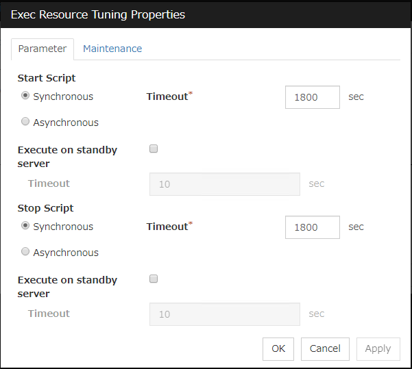
Common to all start scripts and stop scripts
Synchronous
Waits for the script to end when it is run. Select this option for executable files that are not resident (the process is returned immediately after the script completion).
Asynchronous
Does not wait for the script to end when it is run. Select this for resident executable files. The script can be monitored by PID monitor resource if Asynchronous is selected.
Timeout (1 to 9999)
When you want to wait for a script termination (when selecting Synchronous), specify how many seconds you want to wait before a timeout. This box is enabled when Synchronous is selected. Unless the script completes within the specified time, it is determined as an error.
Execute on standby server
Set whether the scripts are to be executed on the standby server. Enabling this parameter allows you to specify the timeout value (1 to 9999) for the execution.
Maintenance tab
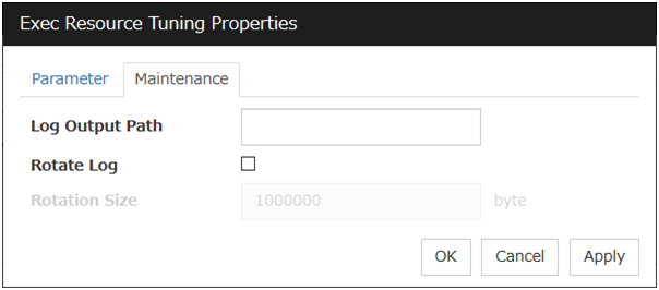
Log Output Path (Within 1023 bytes)
Specify the redirect destination path of standard output and standard error output for EXEC resource scripts and executable files. If this box is left blank, messages are directed to /dev/null. The name should begin with "/."If the Rotate Log check box is off, note the amount of available disk space in the file system because no limit is imposed on message output.If the Rotate Log check box is on, the log file to be output is rotated. Note the following items.
You must specify a log output path within 1009 bytes. If you specify a path of 1010 bytes or more, the log is not output.
You must specify a log file name within 31 bytes. If you specify a log file name of 32 bytes or more, the log is not output.
Rotate Log
Clicking Rotate Log when the Rotate Log check box is not checked outputs the execution logs of the EXEC resource script and the executable file without imposing any limit on the file size. Clicking Rotate Log when the Rotate Log check box is selected rotates and outputs messages.
Rotation Size (1 to 999999999)If the Rotate Log check box is selected, specify a rotation size.The structures of the log files to be rotated and output are as follows:
File name
Description
file_name for the Log Output Path specification
Newest log
file_name.pre for the Log Output Path specification
Previously rotated log
3.7. Understanding Disk resource
3.7.1. Dependencies of Disk resource
Disk resource is supported by the following versions of EXPRESSCLUSTER by default.
Group Resource Type |
|---|
Dynamic DNS resource |
Floating IP resource |
Virtual IP resource |
Volume manager resource |
AWS Elastic IP resource |
AWS Virtual IP resource |
AWS Secondary IP resource |
AWS DNS resource |
Azure DNS resource |
3.7.2. Switching partitions
Note
For "raw" disk type, EXPRESSCLUSTER maps (binds) the switching partition to the raw device of the OS. If Execute Unbind is selected on the Disk Resource Tuning Properties, the unbind process is performed to deactivate the disk resource.
If switching partitions are not accessible with the same device name on all the servers, configure the server individual setup.
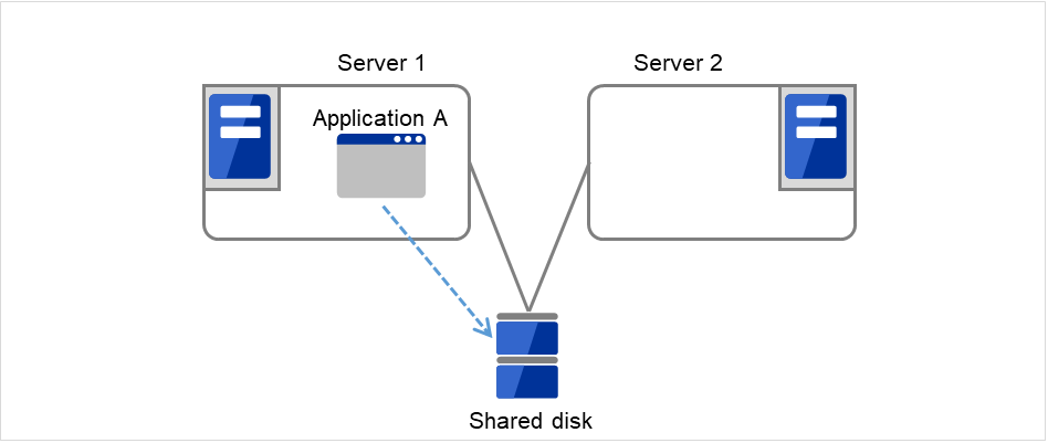
Fig. 3.70 Switching partitions (1)
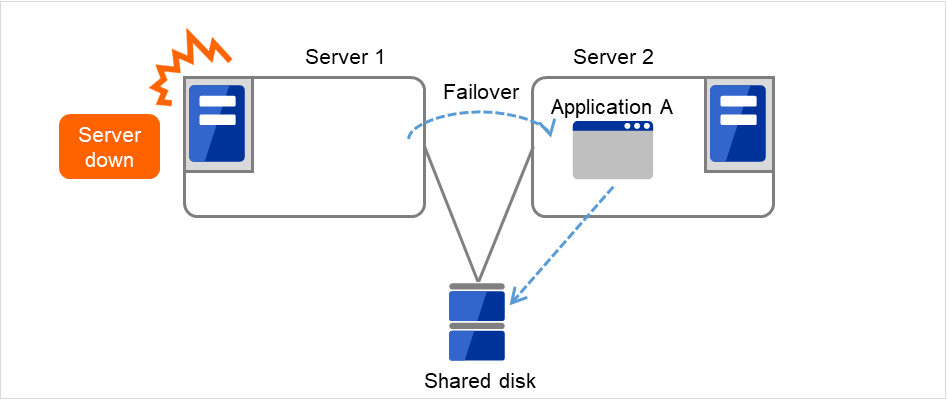
Fig. 3.71 Switching partitions (2)
3.7.3. Device region expansion on disk resources
Follow the steps below to execute region expansion of the device. Be sure to execute the following steps on the server where the disk resource in question has been activated.
Deactivate a group to which the disk resource in question belongs by using a command such as clpgrp.
Confirm that no disks have been mounted by using a command such as mount and df.
- Change the state of the disk from Read Only to Read Write by executing one of the following commands depending on the disk resource type.# clproset -w -d <device-name>
Execute region expansion of the device.
- Change the state of the disk from Read Write to Read Only by executing one of the following commands depending on the disk resource type.# clproset -o -d <device-name>
Activate a group to which the disk resource in question belongs by using a command such as clpgrp.
3.7.4. Notes on disk resources
- EXPRESSCLUSTER controls accesses to the file system (mount/umount). Thus, do not configure the settings about mount/umount on the OS.(If the entry to is required /etc/fstab, please use the noauto option is not used ignore option.)
The partition device name set to the disk resource is in the read-only mode on all servers in a cluster. Read-only status is released when the server is activated.
With Exclude Mount/Unmount Commands checked in the Extension tab of Cluster Properties, activating/deactivating a disk resource may take time. This is because the mounting/unmounting of a disk resource or mirror disk resource is performed exclusively in the same server.
- When specifying path including symbolic link for mount point, Force Operation cannot be done even if it is chosen as operation in Detecting Failure.Similarly, if a path containing "//" is specified, forced termination will also fail.
- If you want to prevent behalf of the device in OS startup, udev devices the Please set the device name.example: /dev/disk/by-label/<device-name>In starting the OS, if you want to prevent the device order from being switched, specify the udev device (e.g. /dev/disk/by-id/[device name]) for a device name.
When a change is made at the run level on the OS, some device files of a partition device set as a disk resource might be created again. This may reset the read-only setting for the partition device set as a disk resource.
<When using a resource that has the disk type LVM>
When using this setting, it is recommended to control a volume group by using a volume manager resource together. For details, see "Understanding Volume manager resources" of this guide.
The volume is not defined on the EXPRESSCLUSTER side.
Please do not select [zfs] for the File System.
3.7.5. Details tab
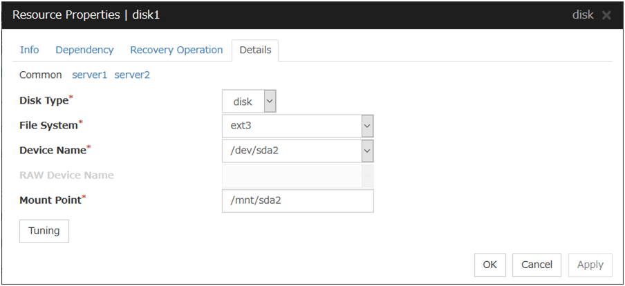
Disk Type Server Individual Setup
Select a disk type. You can only choose [disk].
Choose one of the types below.
DISK
RAW
LVM
File System Server Individual Setup
You select a file system type created on the disk device. Choose one from the types described below. You may also directly enter the type. This setting is necessary when the setting to Disk Type is other than raw.
ext3
ext4
xfs
zfs
Device Name (Within 1023 bytes) Server Individual Setup
Select the disk device name to be used for disk resources. Otherwise, you can enter the device name. When other than [zfs] is selected for File System, the name should begin with "/". If File System is [zfs], specify the ZFS data set name.
Raw Device Name (within 1,023 bytes) Server Individual Setup
Enter the raw disk device name to be used for disk resources. This setting is necessary when the setting to Disk Type is raw.
Mount Point (Within 1023 bytes) Server Individual Setup
Enter the directory to mount the disk device. The name should begin with "/." This setting is necessary when the setting to Disk Type is other than raw.
Tuning
Opens the Disk Resource Tuning Properties dialog box. Make detailed settings on the dialog box.
Disk Resource Tuning Properties(when the setting to Disk Type is other than raw)
Mount tab
The detailed settings related to mount are displayed.
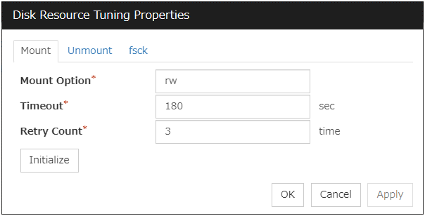
Mount Option
Enter options to give the mount command when mounting the file system on the disk device. More than one option is delimited with a comma ",".
A mount option sample
Setting item
Setting value
Device name
/dev/sdb5
Mount point
/mnt/sdb5
File system
ext3
Mount option
rw,data=journal
The mount command to be run with the above settings is:
mount -t ext3 -o rw,data=journal /dev/sdb5 /mnt/sdb5
Timeout (1 to 999)
Enter how many seconds you want to wait for the mount command completion before its timeout when you mount the file system on the disk device.If the file system has a large size of disk space, it may take some time for the command to complete. Make sure to specify the value that is enough for the mount command completion.
Retry Count (0 to 999)
Enter how many times you want to retry to mount the file system on the disk device when one fails.If you set this to zero (0), mount will not be retried.
Initialize
Clicking Initialize resets the values of all items to the default values.
Unmount tab
The detailed settings related to unmount are displayed.
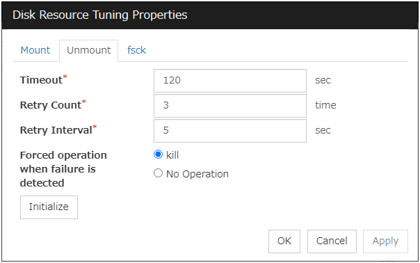
Timeout (1 to 999)
Enter how many seconds you want to wait for the umount command completion before its timeout when you unmount the file system on the disk device.
Retry Count (0 to 999)
Enter how many times you want to retry to unmount the file system on the disk device when one fails. If this is set to zero (0), unmount will not be retried.
Retry Interval (0 to 999)
Enter the interval in which you want to retry unmounting the file system on the disk device when unmounting fails.
Forced operation when failure is detected
Select an action to be taken at an unmount retry if unmount is failed.
Initialize
Clicking Initialize resets the values of all items to the default values.
fsck tab
The detailed settings related to fsck are displayed. The tab appears only if [xfs] is set for the file system. If [zfs] is selected for the file system, it will be invalid.
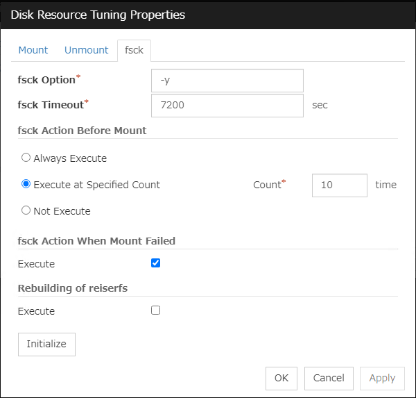
fsck Option (Within 1023 bytes)
fsck Timeout (1 to 9999)
Enter how many seconds you want to wait for the fsck command completion before its timeout when you check the file system on the disk device. If the file system has a large size of disk space, it may take some time for the command to complete. Make sure to specify the value that is enough for the mount command completion.
fsck action before mount
Select an fsck action before mounting file system on a disk device from the following choices:
Note
The number of times to execute fsck is not related to the check interval managed by a file system.
fsck Action When Mount Failed
Set an fsck action when detecting a mount failure on a disk device.This setting is enabled when the setting of Mount Retry Count is other than zero.
Note
It is not recommended to set "Not Execute" fsck action before performing mount. With this setting, disk resource does not execute fsck and disk resource cannot be failed over when there is an error that can be recovered by fsck in the switchable partition.
Rebuilding of reiserfs
Specify the action when reiserfsck fails with a recoverable error.
Initialize
Clicking Initialize resets the values of all items to the default values.
xfs_repair tab
The detailed settings related to [xfs_repair] are displayed. The tab appears only if [xfs] is set for the file system.
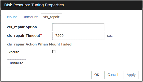
xfs_repair Option (Within 1023 bytes)
Enter the option to give to the [xfs_repair] command when checking the file system on the disk device. To enter multiple options, delimit each with a space.
xfs_repair Timeout (1 to 9999)
Enter how many seconds you want to wait for the [xfs_repair] command completion before its timeout when you check the file system on the disk device. If the file system has a large size of disk space, it may take some time for the command to complete. Make sure that the value to set is not too small.
xfs_repair Action When Mount Failed
Set the [xfs_repair] action when mounting the file system on the disk device fails. This setting is enabled when the setting of Mount Retry Count is other than zero.
Initialize
Clicking Initialize resets the values of all items to the default values.
Disk Resource Tuning Properties (when the setting to Disk Type is raw)
Unbind tab
The detailed settings related to unbind are displayed.
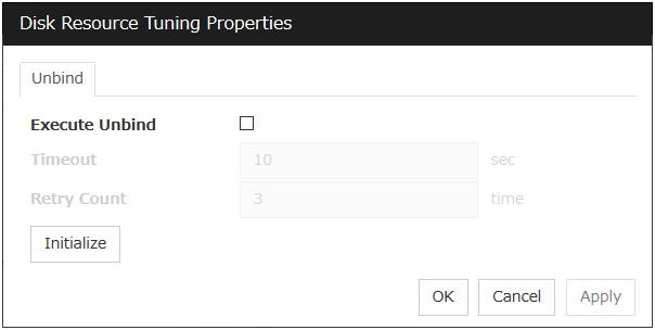
Execute Unbind
Specify whether to execute unbind a raw disk device.
Timeout (1 to 999)
When the Execute Unbind check box is selected, Set the time-out for the unbind completion of the raw disk device.
Retry Count (1 to 999)
When the Execute Unbind check box is selected, Specify the retry count to unbind the raw disk device when one fails.
Initialize
Clicking Initialize resets the values of all items to the default values.
3.8. Understanding Floating IP resource
3.8.1. Dependencies of Floating IP resource
By default, this function does not depend on any group resource type.
3.8.2. Floating IP
Client applications can use floating IP addresses to access cluster servers. By using floating IP addresses, clients do not need to be aware of switching access destination server when a failover occurs or moving a group migration.
Floating IP addresses can be used on the same LAN and over the remote LAN.
Execute the [ifconfig] command or the API to assign an IP address to the OS. The floating IP resource automatically determines whether to execute the [ifconfig] command or the API.
When [ifconfig] command has a format other than the following, execute API.
eth0    Link encap:Ethernet HWaddr 00:50:56:B7:1B:C0
        inet addr:192.168.1.113 Bcast:192.168.1.255 Mask:255.255.255.0
        inet6 addr: fe80::250:56ff:feb7:1bc0/64 Scope:Link

(The following is omitted.)
Clients access Server 1 at its floating IP (FIP) address .
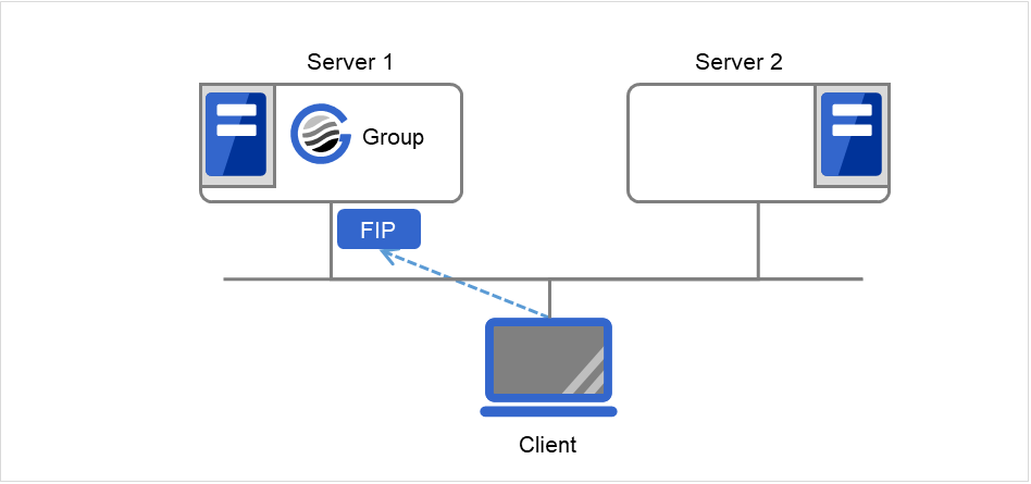
Fig. 3.72 Access to the floating IP address (1)
Even if a failover occurs from Server 1 to Server 2, clients access the FIP address without being aware of the actual, changed destination.
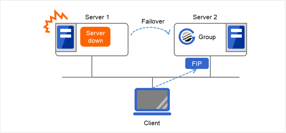
Fig. 3.73 Access to the floating IP address (2)
Address assignment
An IP address to assign for floating IP address needs to meet the condition described below:
Available host address which is in the same network address as the LAN that the cluster server belongs
Allocate as many IP addresses that meet the above condition as required (generally as many as failover groups). These IP addresses are the same as general host addresses, therefore, global IP addresses can be assigned such as Internet.
Switching method
For IPv4, MAC addresses on the ARP table are switched by sending ARP broadcasting packets from the server on which FIP resources are activated.
For IPv6, ARP broadcasting packets are not sent.
The table below shows the information of ARP broadcasting packets sent by EXPRESSCLUSTER:
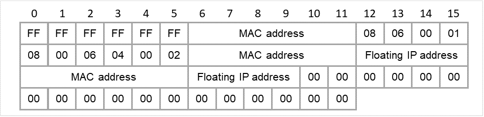
Fig. 3.74 ARP broadcasting packets sent by EXPRESSCLUSTER
Routing
You do not need to configure the settings for the routing table.
Conditions to use
Floating IP addresses are accessible to the following machines:
Cluster server itself
Other servers in the same cluster and the servers in other clusters
Clients on the same LAN as the cluster server and clients on remote LANs
If the following conditions are satisfied, machines other than the above can also access floating IP addresses. However, connection is not guaranteed for all models or architectures of machines. Test the connection thoroughly by yourself before using those machines.
TCP/IP is used for the communication protocol.
ARP protocol is supported.
Even over LANs configured with switching hubs, floating IP address mechanism works properly. When a server goes down, the TCP/IP connection the server is accessing will be disconnected.
3.8.3. Notes on Floating IP resource
Do not execute a network restart on a server on which floating IP resources are active. If the network is restarted, any IP addresses that have been added as floating IP resources are deleted.
IP address overlaps due to time-lag of the [ifconfig] command
If the following is set to the floating IP resource, the failover of resources may fail:
When a value smaller than the default is set to Retry Count at Activation Failure.
When Ping Retry Count and Ping Interval are not set.
This problem occurs due to the following causes:
Releasing IP address may take time depending on the specification of the [ifconfig] command after deactivating the floating IP address on the server from which the resource is failed over.
On the activation of the floating IP address on the server to which the resource is failed over, if the ping command is run to the IP address to be activated in order to prevent dual activation, ping reaches the IP address because of the reason above, and the resource activation error occurs.
Make the following settings to avoid this problem:
Set a greater value to Retry Count at Activation Failure of the resource (default: 5 times).
Set greater values to Ping Retry Count and Ping Interval.
Clients access Server 1 at its floating IP (FIP) address.
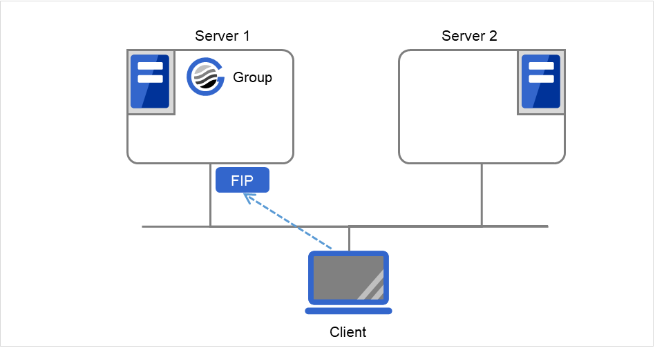
Fig. 3.75 Configuration with a floating IP address (1): in a normal case
Server 1 crashes and a failover occurs.However, while Server 1 cannot immediately release the FIP address, a ping reaches the address from Server 2. Then the FIP address is considered to have been duplicated, which leads to failure in activation on Server 2 (and failure in access from clients to the FIP address).
Fig. 3.76 Configuration with a floating IP address (2): when the failover fails
IP address overlaps when OS is stalled
If OS stalls with the floating IP address activated, the resource failover may fail when the following settings are made:
A value other than 0 is set to Ping Timeout.
Forced FIP Activation is off.
This problem occurs due to the following causes:
A part of OS stalls (as examples below) with the floating IP address activated.
Network modules are running and respond to ping from other nodes
A stall cannot be detected in the user-mode monitor resource
When activating the floating IP address on the server to which the resource is failed over, if the ping command is executed to the IP address to be activated in order to prevent redundant activation, ping reaches the IP address because of the reason above, and the resource activation error occurs.
In the machine environment where this problem often occurs, this can be prevented by the settings below. However, both groups may be activated depending on the status of a stall, and server shutdown may occur depending on the timing of the activation of both groups. For details on activation of both groups, see "What causes servers to shut down" - "Recovery from network partition" in "The system maintenance information" in the "Maintenance Guide".
- Specify 0 to Ping TimeoutOverlap check is not performed to the floating IP address.
- Specify "On" to Forced FIP ActivationThe floating IP address is activated forcibly even when the address is used on a different server.
With Ping Timeout not set at zero (0) and Forced FIP Activation set at off
Due to the stalled OS on Server 1, a failover occurs with the FIP address activated. Immediately after that, however, there is a response to the ping command performed before the FIP address activation on Server 2. This activation fails for preventing dual activation.
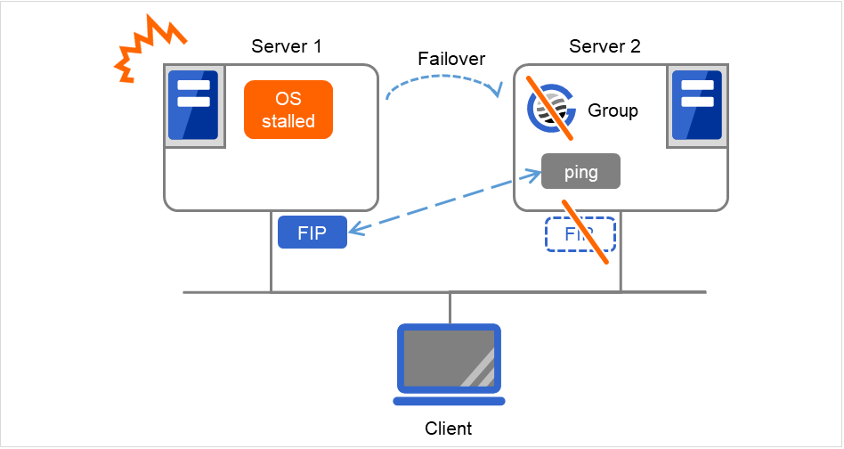
Fig. 3.77 With Ping Timeout not set at zero (0) and Forced FIP Activation set at "Off"
With Ping Timeout set at zero (0)
Due to the stalled OS on Server 1, a failover occurs with the FIP address activated. The FIP address activation succeeds on Server 2, where the ping command to the FIP address is not performed.
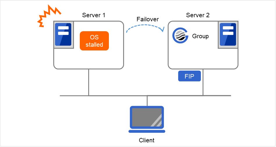
Fig. 3.78 With Ping Timeout set at zero (0)
With Ping Timeout not set at zero (0) and Forced FIP Activation set at on
Due to the stalled OS on Server 1, a failover occurs with the FIP address activated. The FIP address activation forcibly succeeds on Server 2, regardless of the result of the ping command to the FIP address performed by Server 2.
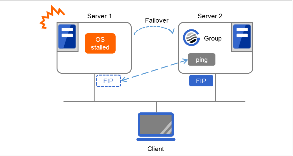
Fig. 3.79 With Ping Timeout not set at zero (0) and Forced FIP Activation set at on
- MAC address of virtual NIC to which floating IP is allocated.When the floating IP resource fails over, the corresponding MAC address is changed because the MAC address of virtual NIC to which the floating IP is allocated is the MAC address of real NIC.
- Source address of IP communication from the running server when the resource activation.The source address from the server is basically the real IP of the server even though the floating IP resource has activated. When you want to change the source address to the floating IP, the settings are necessary on the application.
When Forced FIP Activation is set to ON, if a floating IP address is activated, and then a machine in the same network segment connects to a floating IP address, the connection may be established with a machine that previously used that IP address.
floating IP resource does not supported by the environment that OpenVPN has started.
The NIC name (the name of a network interface card, such as eth0) is up to 15 characters long. If the length of the name exceeds 15 characters, the activation failure occurs. Modify the NIC name in such a case.
Before activating a floating IP resource, [ping] is issued to check whether there is a duplicated IP address. Therefore, if rejection of ICMP reception via a firewall is set to a network device that uses a duplicated IP address, a floating IP address might be duplicated because the existence of duplicated IP addresses cannot be checked by using a [ping] command.
Use only one FIP resource per network address to enable transmission source settings. If there is already an FIP address with which transmission source settings are enabled for the same network address, the activation fails.
For a floating IP resource to enable transmission source settings, specify an IP address in a subnet different from that of a mirror disk connect.
The transmission source change feature changes the existing path information.
The transmission source change feature cannot be used for any IPv6 IP address.
3.8.4. Waiting process for Floating IP resource deactivation
The following process takes place after deactivating of floating IP address.
Waiting process
Execute the [ifconfig] command or the API to acquire a list of IP addresses assigned to the OS. The floating IP resource automatically determines whether to execute the [ifconfig] command or the API. If no floating IP address exists in the IP address list, it is regarded as deactive.
If a floating IP address exists in the IP addresses, one-second waiting takes place. This setting cannot be changed with the Cluster WebUI.
The operation mentioned above is repeated for up to four times at maximum. This number of times cannot be changed by the Cluster WebUI.
When it results in an error, whether the floating IP resource is regarded as having a deactivation error can be changed with Status at Failure under Confirm I/F Deletion on the Deactivity Check tab of the floating IP resource.
Confirming process by the ping command
The ping command is executed to check if there is a response from the floating IP address. If there is no response, it is regarded as deactive.
When there is a response from the floating IP address, one-second waiting takes place. This setting cannot be changed with the Cluster WebUI.
The operation mentioned above is repeated for up to four times at maximum. This number of times cannot be changed by the Cluster WebUI.
The ping command is executed with one-second timeout. This timeout cannot be changed by the Cluster WebUI.
When it results in an error, the status of floating IP resource can be changed in Status at Failure under Confirm I/F Response on the Deactivity Check on the Deactivity Check tab of the floating IP resource.
Note
3.8.5. Details tab
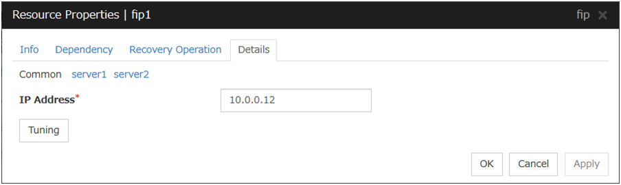
IP Address Server Individual Setup
Enter the floating IP address to be used.Regardless of whether bonding or a tagged VLAN is used or not, specify the value as follows:Example: 10.0.0.12
For more information on environments with bonding, see this guide: "8. Information on other settings" -> "Bonding".The floating IP resource searches for the address on a local computer having the same subnet mask, assuming there to be, by default, 24 mask bits for IPv4 or 128 bits for IPv6. Then, it assigns an alias to the relevant network interface to add a floating IP address.
To specify a number of mask bits explicitly, specify the address followed by /number_of_mask_bits. (For an IPv6 address, be sure to specify /number_of_mask_bits.)
Example: 10.0.0.12/8, fe80::1/8
To specify a network interface explicitly, specify the address followed by %interface_name.
Example: 10.0.0.12%eth1, fe80::1/8%eth1
In the above example, a floating IP address with eight mask bits is added to network interface eth1.
In an environment in which an IPv6 address and the [ifconfig] command can be used, be sure to match the output format of the [ifconfig] command and the IP address notation of the floating IP because the environment is case sensitive.
Tuning
Opens the Floating IP Resource Tuning Properties dialog box where the detailed settings for the floating IP resource can be configured.
Floating IP Resource Tuning Properties
Parameter tab
Detailed settings on parameters for floating IP resource are displayed.
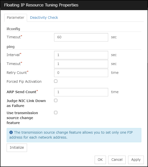
ifconfig
The following is the detailed settings on getting IP addresses and on the [ifconfig] command executed for the activation and/or deactivation of the floating IP resource.
ping
These are the detailed settings of the ping command is used to check if there is any overlapped IP address before activating floating IP resource.
ARP Send Count (0 to 999)
Specify how many times you want to send ARP packets when activating floating IP resources.
If this is set to zero (0), ARP packets will not be sent.
Judge NIC Link Down as Failure
Specify whether to check for an NIC Link Down before the floating IP resource is activated. In some NIC boards and drivers, the required ioctl( ) may not be supported. To check the availability of the NIC Link Up/Down monitor, use the [ethtool] command provided by the distributor. For the check method using the [ethtool] command, see "Note on NIC Link Up/Down monitor resources" in "Understanding NIC Link Up/Down monitor resources" in this guide.
For bonding devices, it is judged as a failure when all the NIC composing the bonding are in the state of Link Down at activation.
Use transmission source change feature
Choose whether to specify a floating IP address as the transmission source.
Initialize
Clicking Initialize resets the values of all items to the default values.
Deactivity Check tab
Detailed settings on deactivity check of floating IP resource are displayed.
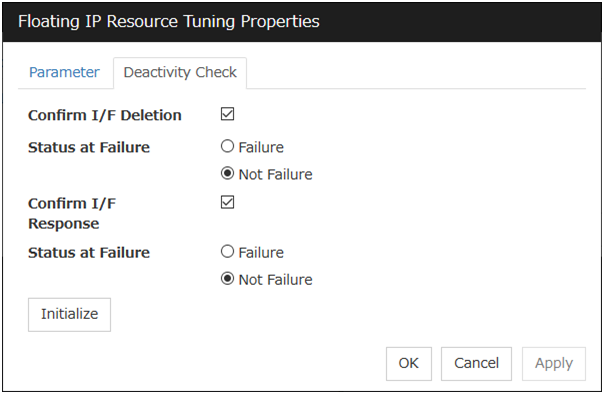
Confirm I/F Deletion
Confirm I/F Response
3.9. Understanding Virtual IP resources
3.9.1. Dependencies of Virtual IP resources
By default, this function does not depend on any group resource type.
3.9.2. Virtual IP resources
Client applications can be connected to a cluster server by using a virtual IP address. The servers can be connected to each other by using a virtual IP address. By using a virtual IP address, switching from one server to the other to which a client is connecting remains transparent even if failover or moving of a failover group occurs. The graphic in the next page shows how virtual IP resources work in the cluster system.
Execute the [ifconfig] command or the API to assign an IP address to the OS. The floating IP resource automatically determines whether to execute the [ifconfig] command or the API. The following shows an example:
For an environment such as RHEL 7 or later (including RHEL compatible operating systems) on which the [ifconfig] command cannot be used, the API is executed.
For an environment such as RHEL 7 or later (including RHEL compatible operating systems) on which the net-tools package enables execution of the [ifconfig] command, the API is executed because the output format of the [ifconfig] command is not compatible with that of RHEL 6 or earlier.
For an environment such as RHEL 6 on which the [ifconfig] command can be used, the [ifconfig] command is executed.
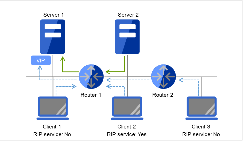
Fig. 3.80 Configuration with a virtual IP address (1)
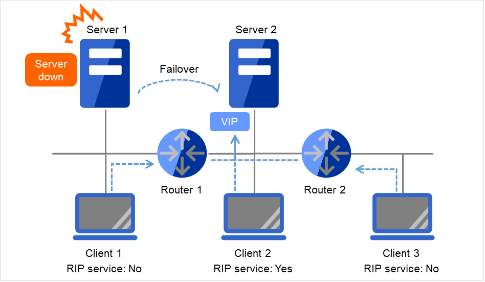
Fig. 3.81 Configuration with a virtual IP address (2)
- Note on setting servers (1)Each cluster server on the same LAN requires being able to change the path by receiving RIP packets, or to resolve path information on the virtual IP address by accessing a router.
- Note on setting servers (2)Each cluster server in a separate segment requires being able to resolve path information on the virtual IP address by accessing a router.
- Note on setting virtual IP resources (1)Specify an IP address outside the LAN to which the cluster servers belong, and free from a collision with existing IP addresses.
- Note on setting routers (1)Each router requires being able to perform dynamic routing by interpreting RIP packets, or to resolve path information on the virtual IP address as static path information.
- Note on setting virtual IP resources (2)Be sure to specify a sender's IP address for each of the servers in order for RIP packets to be correctly sent.
- Note on setting routers (2)Set the flush timer of each router at a value within the heartbeat timeout value.
- Note on setting clients (1)Each client on the same LAN requires being able to change the path by receiving RIP packets, or to resolve path information on the virtual IP address by accessing a router.
- Note on setting clients (2)Each client in a separate segment requires being able to resolve path information on the virtual IP address by accessing a router.
3.9.3. Determining virtual IP address
An IP address used as a virtual IP address should satisfy the following conditions:
The IP address should not be within the network address of the LAN to which the cluster belongs.
The IP address should not conflict with existing network addresses.
Select one of the following allocation methods to meet the requirements above:
Obtain a new network IP address for virtual IP address and allocate virtual IP address.
Determine a network IP address from private IP address space and allocate virtual IP address. The following procedures are given as an example.
Select one network address from 192.168.0 to 192.168.255 for virtual IP address.
Allocate up to 64 host IP addresses for virtual IP address from the network address you have selected. (For example, select the network address 192.168.10 and allocate two host IP addresses: 192.168.10.1 and 192.168.10.254)
Specify 255.255.255.0 to net mask of the virtual IP address.
When you configure multiple virtual IP addresses, dummy virtual IP addresses may be required. For details, see "Preparing for using Virtual IP resources".
Private IP addresses are addresses for a closed network and they cannot be accessed using virtual IP address from outside of the network through internet providers.
Do not disclose path information of private IP addresses outside the organization.
Adjust the private IP addresses to avoid conflict with other address.
3.9.4. Preparing for using Virtual IP resources
If your cluster configuration satisfies the following conditions, you need to set a dummy virtual IP address which has same network address as a virtual IP address on each server.
When multiple virtual IP resources exist in a cluster.
Virtual IP resources whose network address and NIC alias name are same exist in a cluster.
Note
If a dummy virtual IP address cannot be configured, other virtual IP addresses assigned to the same NIC alias might be deleted by the OS when any virtual IP resource is deactivated.
A dummy virtual IP address should satisfy the following conditions:
The IP address has a same network address as of a virtual IP resource, and is unique.
The IP address can be prepared for each server constructing a cluster.
The IP address is prepared for each NIC alias.
In the following settings, a dummy virtual IP address should be configured on each server.
- Virtual IP resource 1IP address 10.0.1.11/24NIC alias name eth1
- Virtual IP resource 2IP address 10.0.1.12/24NIC alias name eth1
For example, set a dummy virtual IP address as follows:
- Dummy virtual IP address of Server 1IP address 10.0.1.100/24NIC alias name eth1:0
- Dummy virtual IP address of Server 2IP address 10.0.1.101/24NIC alias name eth1:0
Configure the OS by the following procedure so that dummy virtual IP addresses are enabled at OS startup.
In the following procedure, eth1 of server 1 is set to 10.0.1.100/24 as an example.
Perform one of the following procedures according to your distribution.
- For SUSE LINUX Enterprise Server:Edit the file on the following path. Add the italic parts on the setting information.
Path
/etc/sysconfig/network/ifcfg-eth1-"MAC_address_of_eth1"
Setting information
BOOTPROTO='static'
BROADCAST='10.0.0.255'
IPADDR='10.0.0.1'
MTU=''
NETMASK='255.255.255.0'
NETWORK='10.0.0.0'
IPADDR_1='10.0.1.100'
NETMASK_1='255.255.255.0'
NETWORK_1='10.0.1.0'
LABEL_1=1
REMOTE_IPADDR=''
STARTMODE='onboot'
UNIQUE='xxxx'
_nm_name='xxxx'
- For other than SUSE LINUX Enterprise Server:Create a file on the following path, and add the setting information.
Path
/etc/sysconfig/network-scripts/ifcfg-eth1:0
Setting information
DEVICE=eth1:0
BOOTPROTO=static
BROADCAST=10.0.1.255
HWADDR=MAC_address_of_eth1
IPADDR=10.0.1.100
NETMASK_1=255.255.255.0
NETWORK=10.0.1.0
ONBOOT=yes
TYPE=Ethernet
Restart the OS.
Dummy virtual IP addresses are enabled after the OS restart. Configure server 2 in the same manner.
Follow the procedure below when the settings above is required due to the cluster configuration change.
Stop a cluster. For the procedure, see "Suspending EXPRESSCLUSTER Stopping the EXPRESSCLUSTER daemon" in "Preparing to operate a cluster system" in the "Installation and Configuration Guide".
Disable the cluster daemon. For the procedure, see "Suspending EXPRESSCLUSTER Disabling the EXPRESSCLUSTER daemon" in "Preparing to operate a cluster system" in the "Installation and Configuration Guide".
Change the settings above.
Restart the OS, and check that the settings are applied.
Enable the cluster daemon. For the procedure, see "Suspending EXPRESSCLUSTER Enabling the disabled EXPRESSCLUSTER daemon" in "Preparing to operate a cluster system" in the "Installation and Configuration Guide".
Modify the cluster configuration. For the procedure, see "Modifying the cluster configuration data" in the "Installation and Configuration Guide".
3.9.5. Controlling path
To access to a virtual IP address from a remote LAN, path information of the virtual IP address must be effective to all routers on the path from the remote LAN to the LAN for cluster server. To be specific, the following condition must be satisfied:
Routers on the cluster servers LAN interpret host RIP.
Routers on the path from a cluster server to the remote server have the dynamic routing settings or information on the virtual IP address routes has configured as static routing settings.
3.9.6. Requirement to use virtual IP address
Environments where virtual IP address can be used
Virtual IP addresses can be accessed from the machines listed below. Virtual IP address mechanism functions properly even in a LAN where switching hubs are used. However, when a server goes down, TCP/IP that has been connected will be disconnected.
When using virtual IP addresses with a switching HUB that cannot be configured to create a host routing table by receiving host RIP, you need to reserve one new network address and configure virtual IP addresses so that the IP address of each server belongs to a different network address.
Cluster servers that belong to the same LAN which the server the virtual IP activates belongs to
Virtual IP addresses can be used if the following conditions are satisfied:
Machines that can change the path by receiving RIP packets.
Machines that can resolve the path information of a virtual IP address by accessing a router.
Cluster servers that belongs to the different LAN from which the server the virtual IP activates belongs to
Virtual IP addresses can be used if the following condition is satisfied:
Machines that can resolve path information of the virtual IP address by accessing a router.
Clients that belongs to the same LAN which cluster servers belong to
Virtual IP addresses can be used if the following conditions are satisfied:
Machines that can change the path by receiving RIP packets.
Machines that can resolve the path information of a virtual IP address by accessing a router.
Clients on remote LAN
Virtual IP addresses can be used if the following condition is satisfied:
Machines that can resolve path information of the virtual IP address by accessing a router.
3.9.7. Notes on Virtual IP resources
Do not execute a network restart on a server on which virtual IP resources are active. If the network is restarted, any IP addresses that have been added as virtual IP resources are deleted.
The following rule applies to virtual IP addresses.
- If virtual IP resources are not inactivated properly (e.g. when a server goes down), the path information of virtual IP resources is not deleted. If virtual IP resources are activated with their path information not deleted, the virtual IP addresses cannot be accessed until their path information is reset by a router or a routing daemon.Thus, you need to configure the settings of a flush timer of a router or a routing daemon. For a flush timer, specify the value within the heartbeat timeout value. For details on the heartbeat timeout, see "Cluster properties" in "2. Parameter details" in this guide.
MAC address of virtual NIC to which virtual IP is allocated.
When the virtual IP resource fails over, the corresponding MAC address is changed because the MAC address of virtual NIC to which the virtual IP is allocated is the MAC address of real NIC.
Source address of IP communication from the running server when the resource activation.
The source address from the server is basically the real IP of the server even though the virtual IP resource has activated. When you want to change the source address to the virtual IP, the settings are necessary on the application.
Routing protocol used
If the routing protocol is set to "RIPver2," the subnet mask for transmitted RIP packets is "255.255.255.255" .
3.9.8. Details tab
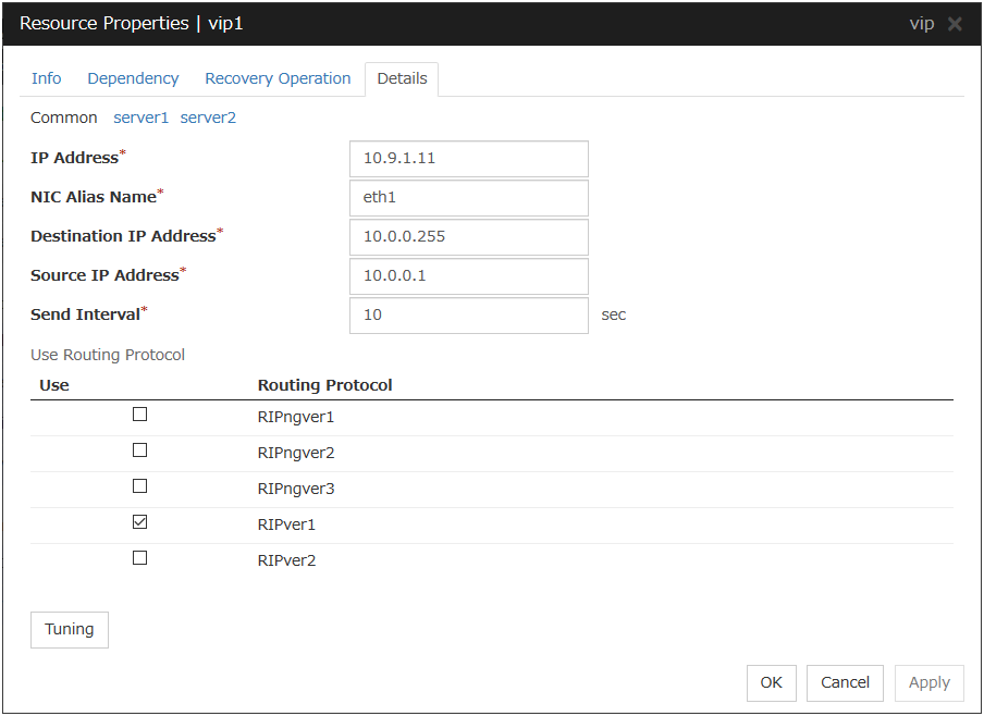
IP Address Server Individual Setup
Enter the virtual IP address to use. To specify a number of mask bits explicitly, specify the address followed by /number_of_mask_bits. (For an IPv6 address, be sure to specify /number_of_mask_bits.)
NIC Alias Name Server Individual Setup
Enter the NIC interface name that activates the virtual IP address to be used.
Destination IP Address Server Individual Setup
Enter the destination IP address of RIP packets. IPv4 specifies the broadcast address and IPv6 specifies the router IPv6 address.
Source IP Address Server Individual Setup
Enter the IP address to bind when sending RIP packets. Specify the actual IP address activated on NIC which activates the virtual IP address.
To use an IPv6 address, specify a link local address as the source IP address.
Note
The source IP address should be set for individual servers, and set the actual IP address of each server. Virtual IP resources do not operate properly if a source address is invalid. In the Common tab, describes the source IP address of any server, other servers, please to perform the individual setting.
Send Interval (1 to 30) Server Individual Setup
Specify the send interval of RIP packets.
Use Routing Protocol Server Individual Setup
Specify the RIP version to use. For IPv4 environment, select RIPver1 or RIPver2. For IPv6 environment, select RIPngver1 or RIPngver2 or RIPngver3. You can select more than one routing protocols.
Tuning
Opens Virtual IP resource Tuning Properties. You can make the advanced settings for the virtual IP resources.
Virtual IP Resource Tuning Properties
Parameter tab
Detailed setting for virtual IP parameter is displayed.
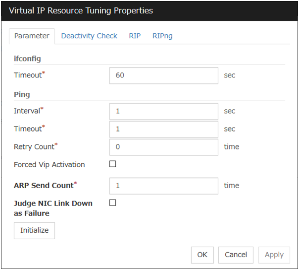
ifconfig
The following is the detailed settings on getting IP addresses and on the ifconfig command executed for the activation and/or deactivation of the virtual IP resource.
Ping
In this box, make detailed settings of the ping command used to check for any overlapped IP address before activating the virtual IP resource.
ARP Send Count (0 to 999)
Specify how many times you want to send ARP packets when activating virtual IP resources.
If this is set to zero (0), ARP packets will not be sent.
Judge NIC Link Down as Failure
Specify whether to check for an NIC Link Down before the virtual IP resource is activated. In some NIC boards and drivers, the required ioctl( ) may not be supported. To check the availability of the NIC Link Up/Down monitor, use the [ethtool] command provided by the distributor. For the check method using the [ethtool] command, see "Note on NIC Link Up/Down monitor resources" in "Understanding NIC Link Up/Down monitor resources" in this guide.
Initialize
Click Initialize to reset the values of all items to their default values.
Deactivity Check tab
Detailed settings on deactivity check of virtual IP resource are displayed.
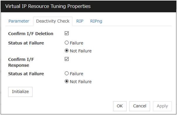
Confirm I/F Deletion
After deactivating the virtual IP, the cluster makes sure that the given virtual IP address disappeared successfully. Configure if failure is treated as the IP resource deactivity failure.
Confirm I/F Response
After deactivating a virtual IP, a cluster makes sure that the given virtual IP address cannot be accessed by the ping command. Configure reaching the virtual IP address by the ping command is treated as deactivity failure.
RIP tab
Detailed settings on RIP of virtual IP resource are displayed.
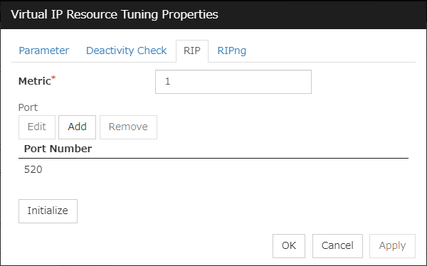
Metric (1 to 15)
Enter a metric value of RIP. A metric is a hop count to reach the destination address.
Port
On Port Number, a list of communication ports used for sending RIP is displayed.
Add
Add a port number used for sending RIP. Clicking this button displays the dialog box to enter a port number.

Port No.
Enter a port number to be used for sending RIP, and click OK.
Edit
A dialog box to enter a port number is displayed. The port selected in the Port Number is displayed. Edit it and click OK.
Remove
Click Remove to remove the selected port on the Port Number.
RIPng tab
Detailed settings on RIPng of virtual IP resource are displayed.
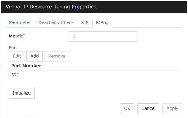
Metric (1 to 15)
Enter a metric value of RIPng. A metric is a hop count to reach the destination address.
Port
On Port Number, a list of ports used for sending RIPng is displayed.
Add
Add a port number used for sending RIPng. Clicking this button displays the dialog box to enter a port number.

Port No.
Enter a port number to be used for sending RIPng, and click OK.
Edit
A dialog box to enter a port number is displayed. The port selected in the Port Number is displayed. Edit it and click OK.
Remove
Click Remove to remove the selected port on the Port Number.
3.10. Understanding Mirror disk resources
3.10.1. Dependencies of Mirror disk resource
By default, this function depends on the following group resource type.
Group resource type |
|---|
Floating IP resource |
Virtual IP resource |
AWS Elastic IP resource |
AWS Virtual IP resource |
AWS Secondary IP resource |
3.10.2. Mirror disk
Mirror disk
Mirror disks are a pair of disks that mirror disk data between two servers in a cluster.
The following figure illustrates mirroring disk data by a pair of Mirror disk 1 with Server 1 and Mirror disk 2 with Server 2:
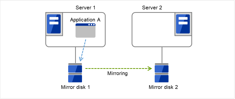
Fig. 3.82 Mirror disk configuration (1)
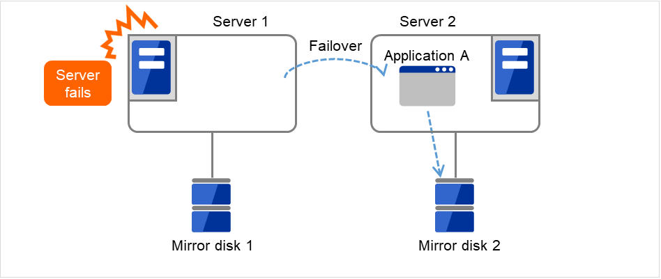
Fig. 3.83 Mirror disk configuration (2)
Data partition
Partitions where data to be mirrored (such as application data) is stored are referred to as data partitions. Allocate data partitions as follows:
- Data partition sizeThe size of data partition should be 1GB or larger but smaller than 1TB.(Less than 1TB size is recommended from the viewpoint of the construction time and the restoration time of data.)
- Partition ID83(Linux)
- If Execute initial mkfs is selected in the cluster configuration information, a file system is automatically created when a cluster is generated.
- EXPRESSCLUSTER is responsible for the access control (mount/umount) of file system. Do not configure the settings that allow the OS to mount or unmount a data partition.
Cluster partition
Dedicated partitions used in EXPRESSCLUSTER for mirror partition controlling are referred to as cluster partition.
Allocate cluster partitions as follows:
- Cluster partition size1024MiB or more. Depending on the geometry, the size may be larger than 1024MB, but that is not a problem.
- Partition ID83(Linux)
- A cluster partition and data partition for data mirroring should be allocated in a pair.
- Do not make the file system on cluster partitions.
- EXPRESSCLUSTER performs the access control of the file system (mount/umount) as a device to mount the mirror partition device. Thus, do not configure the settings to mount or unmount the cluster partition on the OS side.
Mirror Partition Device (/dev/NMPx)
One mirror disk resource provides the file system of the OS with one mirror partition. If a mirror disk resource is registered to the failover group, it can be accessed from only one server (it is generally the primary server of the resource group).
Typically, the mirror partition device (dev/NMPx) remains invisible to users (AP) because they perform I/O via a file system. The device name is assigned so that the name does not overlap with others when the information is created by the Cluster WebUI.
- EXPRESSCLUSTER is responsible for the access control (mount/umount) of file system. Do not configure the settings that allow the OS to mount or unmount a data partition.Mirror partition's (mirror disk resource's) accessibility to applications is the same as switching partition (disk resources) that uses shared disks.
Mirror partition switching is done for each failover group according to the failover policy.
Mirror disk connect
Maximum of two mirror disk connects can be registered per mirror disk resource.
When two mirror disk connects are registered, operations such as switching etc. are as follows:
The paths used to synchronize mirror data can be duplicated. By setting this, mirror data can be synchronized even when one of the mirror disk connects becomes unavailable due to such as disconnection.
The speed of mirroring does not change.
When mirror disk connects switch during data writing, mirror break may occur temporarily. After switching mirror disk connects completes, differential mirror recovery may be performed.
When mirror disk connects switch during mirror recovery, mirror recovery may suspended. If the setting is configured so that the automatic mirror recovery is performed, mirror recovery automatically resumes after switching mirror disk connects completes. If the setting is configured so that the automatic mirror recovery is not performed, you need to perform mirror recovery again after switching mirror disk connects completes.
For the mirror disk connect settings, see "Cluster properties""Interconnect tab" in "2. Parameter details" in this guide.
Disk partition
It is possible to allocate a mirror disk partition (cluster partition, data partition) on a disk, such as root partition or partition, where the OS is located
- When maintainability at a failure is important:It is recommended to allocate a disk for mirror which is not used by the OS (such as root partition, swap partition).
- If LUN cannot be added due to H/W RAID specifications:If you are using hardware/RAID preinstall model where the LUN configuration cannot be changed, you can allocate a mirror partition (cluster partition, data partition) in the disk where the OS (root partition, swap partition) is located.
Example: Adding a SCSI disk to each server to create a pair of mirroring disks.
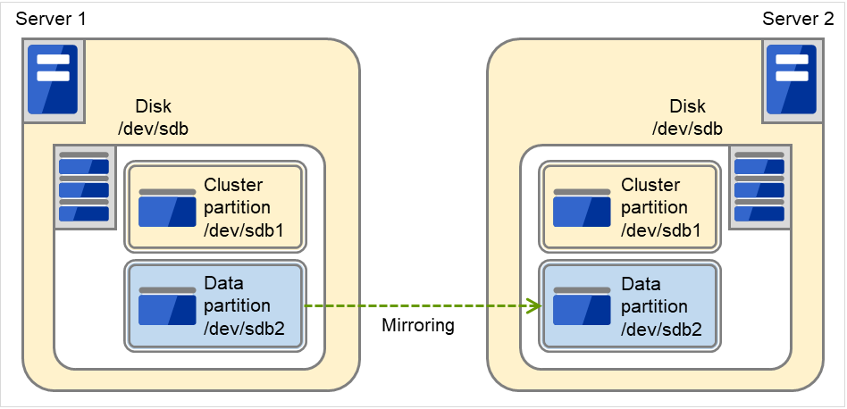
Fig. 3.84 Adding a disk for a mirror partition
Example: Using available area of the IDE disks of each server on which OS of is stored to create a pair of mirroring disks.
The following figure illustrates using the free space of each disk as a mirror partition device (cluster partition and data partition):
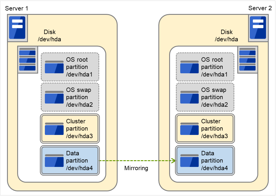
Fig. 3.85 Using the free space of each disk for a mirror partition
- Disk allocationYou may use more than one disk for mirror disk. You may also allocate multiple mirror partition devices to a single disk.
Example: Adding two SCSI disks to each server to create two pairs of mirroring disks.
The following figure illustrates using mirror partitions prepared from two pairs of disks on which partitions of the same size are created:
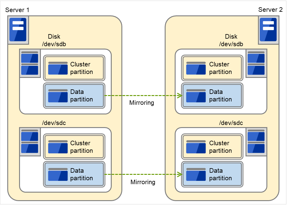
Fig. 3.86 Using two pairs of disks as mirror partitions
Example: Adding a SCSI disk for each server to create two mirroring partitions.
The following figure illustrates each disk on which two pairs of a cluster partition and a data partition are created:
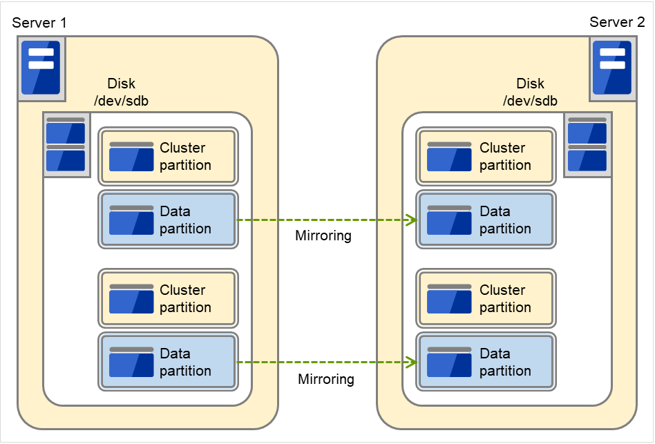
Fig. 3.87 Using multiple areas of each disk for two mirror partitions
3.10.3. Understanding mirror parameters
Mirror Data Port Number
Set the TCP port number used for sending and receiving mirror data between servers. It needs to be configured for individual mirror disk resources.
The default value is displayed when a mirror disk resource is added in Cluster WebUI based on the following condition:
A port number of 29051 or later which is unused and the smallest
Heartbeat Port Number
Set the port number that a mirror driver uses to communicate control data between servers. It needs to be configured for individual mirror disk resources.
The default value is displayed when a mirror disk resource is added in Cluster WebUI based on the following condition:
A port number of 29031 or later which is unused and the smallest
ACK2 Port Number
Set the port number that a mirror driver uses to communicate control data between servers. It needs to be configured for individual mirror disk resources.
The default value is displayed when a mirror disk resource is added in Cluster WebUI based on the following condition:
A port number of 29071 or later which is unused and the smallest
The maximum number of request queues
Configure the number of queues for I/O requests (write requests) from the higher layer of the OS to the mirror disk driver. If a larger value is selected, the write performance will improve but more physical memory will be required.
Note the following when setting the number of queues:
The improvement in the performance is expected when a larger value is set under the following conditions:
Large amount of physical memory is installed on the server and there is plenty of available memory.
Connection Timeout
This timeout is used for the time passed waiting for a successful connection between servers when recovering mirror or synchronizing data.
Send timeout
This timeout is used:
For the time passed waiting for the write data to be completely sent from the active server to the standby server from the beginning of the transmission at mirror return or data synchronization.
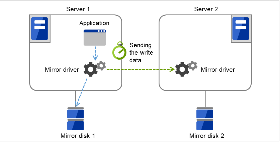
Fig. 3.88 Send timeout (for the write data)
In detail, this timeout is to wait for write data to be completely stored in the send buffer of a network (TCP) once data storing begins. If the TCP buffer is full and there is no free space, a timeout occurs.
For the time interval for checking if the ACK send (in which the active server notifies the standby server of write completion) is necessary.
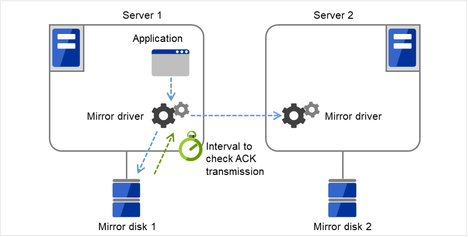
Fig. 3.89 Send timeout (for checking for the ACK send)
Receiving timeout
This timeout is used for the time passed waiting for the standby server to completely receive the write data from the active server from the beginning of the transmission.
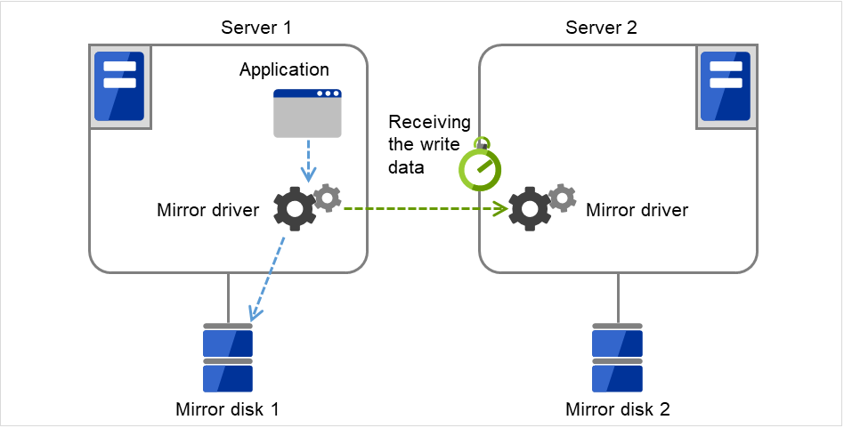
Fig. 3.90 Receiving timeout
Ack timeout
- This timeout is used for the time passed waiting for the active server to receive the ACK notifying the completion of write once the active server begins sending write data to the standby server.If the ACK is not received within the specified timeout time, the difference information is accumulated to the bitmap for difference on the active server.
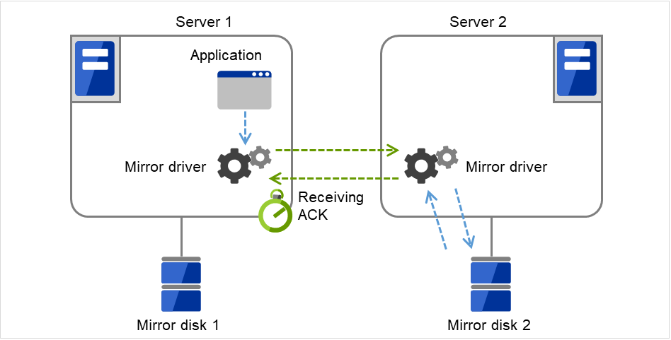
Fig. 3.91 ACK timeout (for the ACK to be received from the standby server)
If you use the synchronous mode, a response to an application might wait until receiving the ACK or until it's timeout.If you use the asynchronous mode, a response to an application is returned after writing to the active server's disk. (This response does not wait for ACK). - This timeout is used for the time passed waiting for the standby server to receive the ACK from the active server after the standby server completely sent the ACK notifying the completion of write.If the ACK for the active server is not received within the specified timeout time, the difference information is accumulated to the bitmap for difference on the standby server.
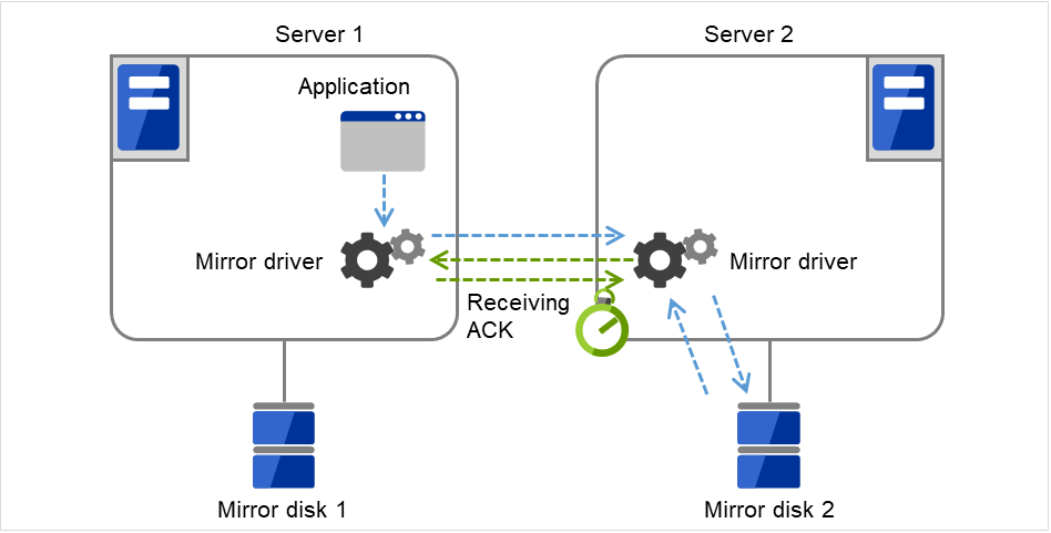
Fig. 3.92 ACK timeout (for the ACK to be received from the active server)
This timeout is used for the time passed waiting for the copy source server to receive the ACK notifying completion from the copy destination server after it began the data transmission when recovering mirror.
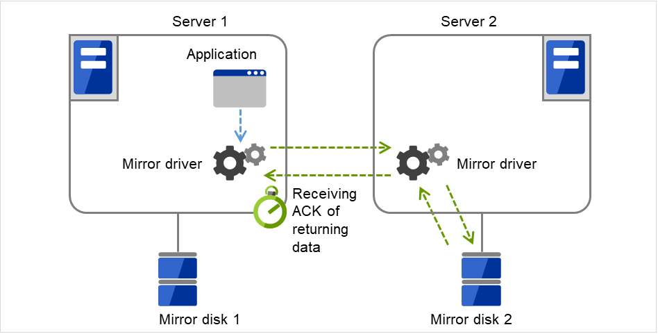
Fig. 3.93 ACK timeout (for the ACK to be received for recovery data)
When the sending amount of the recovery data reaches the Recovery Data Size, 1 ACK is returned (Recovery Data Size is described below.)Therefore when the Recovery Data Size becomes larger, sending becomes more efficient. But if an ACK timeout occurred, re-send data size also becomes larger.
Heartbeat Interval (1 to 600)
Heartbeat interval (sec) for checking the soundness of the mirror disk connect between the mirror drivers of two servers. Use the default whenever possible.
ICMP Echo Reply Receive Timeout (1 to 100)
Value used for heartbeat that is performed to check the soundness of the mirror disk connect between the mirror drivers of two servers. The maximum wait time from when ICMP Echo Request is sent until ICMP Echo Reply is received from the destination server. If ICMP Echo Reply is not received even if this timeout elapses, the reception is repeated for up to the ICMP Echo Request retry count, explained later. Use the default whenever possible.
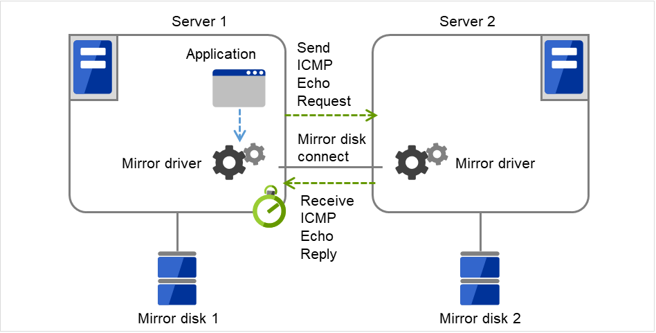
Fig. 3.94 ICMP echo reply receive timeout
ICMP Echo Request Retry Count (1 to 50)
Enter how many times you want to retry at the maximum to send ICMP Echo Request if ICMP Echo Reply from the destination server to ICMP Echo Request cannot be received before the ICMP Echo Reply receive timeout. Use the default whenever possible.
Adjustment between the ICMP Echo Reply receive timeout and ICMP Echo Request retry count.
You can adjust the sensitivity that determines mirror disk connect disconnection by adjusting the ICMP Echo Reply receive timeout and ICMP Echo Request retry count.
Increasing the value
Case in which a network delay occurs in a remote location
Case in which a temporary failure occurs in a network
Decreasing the value
Case in which the time for detecting a network failure is to be reduced
Difference Bitmap Update Interval
Information to be written to the bit map for difference is temporarily accumulated in memory, and is written to the cluster partition at regular intervals. This interval is used for the standby server to check whether this is information to write to the bit map as well as to perform a write.
Difference Bitmap Size
Users can set the difference bitmap size.
If the data partition size is large, there are times efficiency of differential copy can be better by enlarging the size of difference bitmap.
However, memory efficiency could be deteriorated. Please use the default value under normal conditions.
This setting is needed to be set before establishing a mirror disk resource and/or a hybrid disk resource in the cluster. If the mirror disk resource and/or the hybrid disk resource already exist in the cluster, the setting cannot be changed.
Initial Mirror Construction
Specify if configure initial mirroring 4 when activating cluster for the first time after the cluster is created.
- Execute the initial mirror constructionAn initial mirroring is configured when activating cluster for the first time after the cluster is created.The time that takes to construct the initial mirror is different from ext3/ext4/xfs and other file systems.
- Do not execute initial mirror constructionDoes not configure initial mirroring after constructing a cluster.Before constructing a cluster, it is necessary to make the content of mirror disks identical without using EXPRESSCLUSTER.
- 4
Regardless of the existence of the FastSync Option, the entire data partition is copied.
Initial mkfs
Specify if initial file creation in the data partition of the mirror disk is configured when activating cluster for the first time after the cluster is created.
- Execute initial mkfsThe first file system is created when activating cluster for the first time immediately after the cluster is created.
- Do not execute initial mkfsDoes not create a first file system to the data partition in the mirror disk when activating cluster for the first time immediately after the cluster is created.You can configure the settings so that the initial mkfs setting is not executed when a file system has been set up in the data partition of the mirror disk and contains data to be duplicated, which does not require file system construction or initialization by mkfs.The mirror disk partition 5 configuration should fulfill mirror disk resource requirements.
- 5
There must be a cluster partition in a mirror disk. If you cannot allocate a cluster partition when the single server disk is the mirroring target, take a backup and allocate the partition.
If Does not execute initial mirror construction is selected, Execute initial mkfs cannot be chosen. (Should mkfs be performed for the active and standby data partitions, even immediately after mkfs is performed, differences will arise between the active data partition and standby data partition for which mkfs has been executed. Therefore, when initially executing mkfs, initial mirror construction (copying of the active data partition and the standby data partition) is also required. If [Execute initial mirror construction] is selected, [Execute initial mkfs] can be chosen.)
Mode
Switch the synchronization mode of mirroring.
Mode |
Overview |
Explanation |
|---|---|---|
Synchronous |
Complete match of the data in the active and standby servers is guaranteed. |
Writing the data to the mirrored disk is finished when writing the data to both local and remote disks is finished. |
Asynchronous |
The order to write in the updated data is guaranteed. However, the latest updated data may be lost, if a failover is performed in the state that a mirror disk resource cannot be deactivated as servers are down.
The data is transferred to the remote disk after writing request is queued and performed on the background.
|
Writing the data to the mirrored disk is finished when writing the data to the local disk is finished.
After queuing is kept in the kernel space memory, it is transferred to the user space memory. When the volume of data reaches a limit that the user space memory can keep, the data is sent out to a temporary file and kept there.
|
Number of Queues
Rate limitation of Mirror Connect
Note
This function imposes a limit on the communication band by having a maximum one-second pause when the total amount of data to be transferred per second exceeds the configured value. If the amount of data to be written to the disk at one time exceeds the configured value, the expected level of performance may not be achieved. For example, when the amount of data to be transferred to a copy of a mirror disk at one time is 64 KB, even if you set a communication band limit of 64 KB or less per second, the actual amount of communication during copy can be greater than the configured value.
History File Store Directory
Size Limitation of History File
Specify the maximum accumulation in the history file in the Asynchronous mode. When the accumulation reaches the maximum, a mirror break occurs.
Mirroring will also stop when the size of the area for managing the number of cases where data is yet to be sent reaches the upper limit of History Recording Area Size in Asynchronous Mode. This applies even if the total amount of the temporary files does not reach its upper limit. For more information, see "Cluster properties" -> "Mirror driver tab ~ For Replicator/Replicator DR ~" -> "History Recording Area Size in Asynchronous Mode".
Compress Data
Specify whether to compress mirror synchronous data (in the case of Asynchronous mode) or mirror recovery data before transmission. If a slow network is used, compressing transmission data can reduce the amount of data to be transmitted.
Note
Compression may increase the CPU load at data transmission.
In a slow network, compression reduces the amount of data transmitted, so a reduction in time can be expected compared to uncompressed data. Conversely, in a fast network, increases in compression processing time as well as load are more noticeable than a reduction in transfer time, so a reduction in time might not be expected.
If most of data has a high compression efficiency, compression reduces the amount of data transmitted, so a reduction in time can be expected compared to uncompressed data. Conversely, if most of data has a low compression efficiency, not only the amount of data transmitted is not reduced, but also the compression processing time and load increase, in which case a reduction in time might not be expected.
Mirror agent send time-out
Time-out for the mirror agent waiting to complete processing data after sending a request to the other server.

Fig. 3.95 Mirror agent send time-out
Mirror agent receiving time-out
Time-out for the mirror agent waiting to start receiving data after the mirror agent creates a communication socket with the other server.
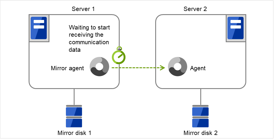
Fig. 3.96 Mirror agent receiving time-out
Recovery Data Size (64 to 32768)
Specify the size of data in mirror recovery between two servers in one processing. The default size is used in general.
Specify a larger size
It takes less time to completely process mirror recovery because the number of data exchanges between two servers decreases.
- During mirror recovery, disk performance may degrade.(This is because, if the disk read range for mirror recovery data and the disk write range for a file system overlap, access is excluded and a wait occurs until the first processing is complete.In a slow network environment, if there is a large amount of recovery data, a single data transfer for mirror recovery will take more time. If a normal disk access for mirror data and this data transfer range for mirror recovery overlap, disk access is awaited until the transfer is complete. This may lead to degraded disk performance.Therefore, specify a smaller size, especially for a slow network environment.)
Specify a smaller size
Sending/receiving data between two servers gets segmented and the possibility for a timeout to occur is decreased with a slow network speed or a high server load.
Because the number of exchanges between two servers increases, mirror recovery takes more time, especially in a network where delay occurs easily.
Encrypt mirror communication
3.10.4. Examples of mirror disk construction
If you are using a disk that has been used as a mirror disk in the past, you must format the disk because old data exists in its cluster partition. For the initialization of a cluster partition, refer to the " Installation and Configuration Guide".
- Execute the initial mirror constructionExecuting initial mkfs
First, install EXPRESSCLUSTER. Next, execute the initial mkfs to the disk connected to Server 1 and that to Server 2.
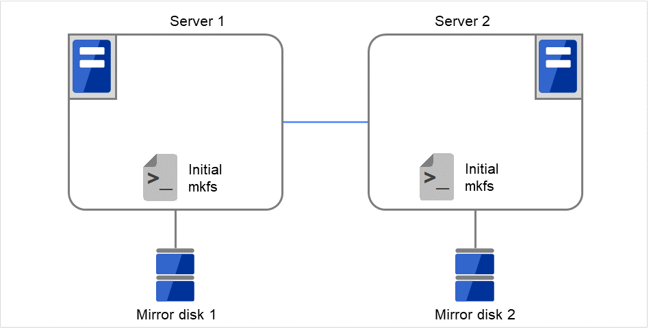
Fig. 3.97 Example of mirror disk construction: executing both initial mkfs and initial mirror construction (1)
Then start the initial mirror construction. Completely copy the content of Mirror disk 1 on Server 1 to Mirror disk 2 on Server 2.

Fig. 3.98 Example of mirror disk construction: executing both initial mkfs and initial mirror construction (2)
- Execute the initial mirror constructionNot executing initial mkfs
First, create application data to be duplicated (if available before the cluster construction) in the data partition (e.g. initial database) of Mirror disk 1 on the active server in advance. For information on the partition configuration, refer to "3.10.2. Mirror disk". Next, install EXPRESSCLUSTER on each of Server 1 and Server 2.
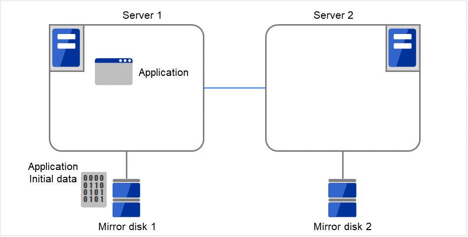
Fig. 3.99 Example of mirror disk construction: executing only initial mirror construction (1)
Then start the initial mirror construction. Completely copy the content of Mirror disk 1 on Server 1 to Mirror disk 2 on Server 2.
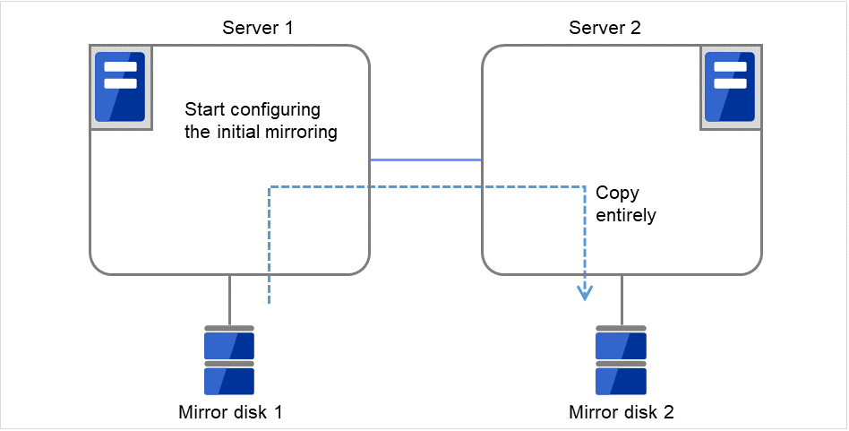
Fig. 3.100 Example of mirror disk construction: executing only initial mirror construction (2)
- Do not execute initial mirror constructionNot executing initial mkfs
The following is an example of making the mirror disks of both servers identical. (This cannot be done after constructing the cluster. Be sure to perform this before the cluster construction.)
Example 1
Copying partition images of a disk
First, create application data to be duplicated (if available before the cluster construction) in the data partitions (e.g. initial databases) of Mirror disk 1 on the active server in advance. For information on the partition configuration, refer to "3.10.2. Mirror disk".

Fig. 3.101 Example of mirror disk construction: copying partition images (1)
Remove Mirror disk 2 from the standby server (Server 2), and connect the disk to the active server (Server 1).
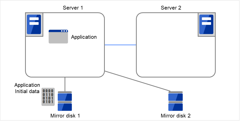
Fig. 3.102 Example of mirror disk construction: copying partition images (2)
With Mirror disk 1 (for the active server) unmounted, copy the full content of the data partitions on Mirror disk 1 to those on Mirror disk 2 (e.g. by using the dd command).Note that copying via the file system brings different partition images.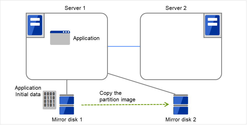
Fig. 3.103 Example of mirror disk construction: copying partition images (3)
Remove Mirror disk 2 from the active server (Server 1), and return the disk to the standby server (Server 2).Then install EXPRESSCLUSTER.After that, construct the cluster as described in "Do not execute initial mirror construction. Not executing initial mkfs" .The initial construction/synchronization of the mirror partition is not to be performed.
Fig. 3.104 Example of mirror disk construction: copying partition images (4)
Example 2
Copying by a backup device
First, create application data to be duplicated (if available before the cluster construction) in the data partitions (e.g. initial databases) of Mirror disk 1 on the active server in advance.For information on the partition configuration, refer to "3.10.2. Mirror disk".
Fig. 3.105 Example of mirror disk construction: using a backup device (1)
Connect a backup device to the active server (Server 1).Back up data in the data partitions on Mirror disk 1, by using a command (e.g. dd command) for partition image backup.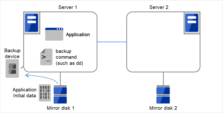
Fig. 3.106 Example of mirror disk construction: using a backup device (2)
Connect the backup device to the standby server (Server 2). Then, to a backup device on Server 2, move the medium used for backing up the data on the active server (Server 1).
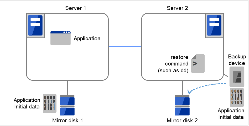
Fig. 3.107 Example of mirror disk construction: using a backup device (3)
Install EXPRESSCLUSTER.After that, construct the cluster as described in "Do not execute initial mirror construction. Not executing initial mkfs". The initial construction/synchronization of the mirror partition is not to be performed.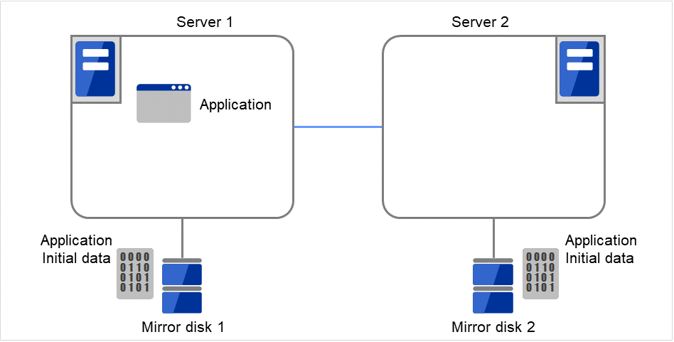
Fig. 3.108 Example of mirror disk construction: using a backup device (4)
3.10.5. Notes on mirror disk resources
If both servers cannot access the identical partitions under the identical device name, configure the server individual setting.
With Exclude Mount/Unmount Commands checked in the Extension tab of Cluster Properties, activating/deactivating a mirror disk resource may take time. This is because the mounting/unmounting of a disk resource or mirror disk resource is performed exclusively in the same server.
- When specifying path including symbolic link for mount point, Force Operation cannot be done even if it is chosen as operation in Detecting Failure.Similarly, if a path containing "//" is specified, forced termination will also fail.
Disks using stripe set, volume set, mirroring, stripe set with parity by Linux md cannot be specified for the cluster partition and data partition.
- Volumes by Linux LVM can be specified for the cluster partition and data partition.For SuSE Linux, volumes by LVM or MultiPath cannot be used for the cluster partition or data partition.
Mirror disk resources (mirror partition devices) cannot be the targets of stripe set, volume set, mirroring, stripe set with parity by Linux md or LVM.
When the geometries of the disks used as mirror disks differ between the servers:
The size of a partition allocated by the fdisk command is aligned by the number of blocks (units) per cylinder.
Allocate data partitions to achieve the following data partition size and direction of the initial mirror construction.
Source server <= Destination server
"Source server" refers to the server with the higher failover policy in the failover group to which a mirror resource belongs."Destination server" refers to the server with the lower failover policy in the failover group to which a mirror resource belongs.If the data partition sizes differ significantly between the copy source and the copy destination, initial mirror construction may fail. Be careful, therefore, to secure data partitions of similar sizes.Make sure that the data partition sizes do not cross over 32GiB, 64GiB, 96GiB, and so on (multiples of 32GiB) on the source server and the destination server. For sizes that cross over multiples of 32GiB, initial mirror construction may fail.Examples)
Combination
Data partition size
Description
On server 1
On server 2
OK
30GiB
31GiB
OK because both are in the range of 0 to 32GiB.
OK
50GiB
60GiB
OK because both are in the range of 32GiB to 64GiB.
NG
30GiB
39GiB
Error because they are crossing over 32GiB.
NG
60GiB
70GiB
Error because they are crossing over 64GiB.
- Do not use the O_DIRECT flag of the open() system call for a file used in a mirror disk resource.Examples include the Oracle parameter filesystemio_options = setall.
Do not specify a mirror partition device (such as /dev/NMP1) as the monitor target in the READ (O_DIRECT) disk monitoring mode.
For the data partition and the cluster partition of mirror disk resources, use disk devices with the same logical sector size on all servers. If you use devices with different logical sector sizes, they do not operate normally. They can operate even if they have different sizes for the data partition and the cluster partition.
Examples)
Combination
Logical sector size of the partition
Description
Server 1
Server 1
Server 2
Server 2
OK
512B
512B
512B
512B
The logical sector sizes are uniform.
OK
4KB
512B
4KB
512B
NG
4KB
512B
512B
512B
The logical sector sizes for the data partitions are not uniform.
NG
4KB
4KB
4KB
512B
The logical sector sizes for the cluster partitions are not uniform.
Do not use HDDs and SSDs in combination for the disks used for the data partition and the cluster partition of mirror disk resources. If you used them in combination, optimum performance cannot be obtained. Even if disks with different disk types are used for the data partition and the cluster partition, they can operate.
Examples)
Combination
Logical sector size of the partition
Description
Server 1
Server 1
Server 2
Server 2
DatapartitionClusterpartitionDatapartitionClusterpartitionOK
HDD
HDD
HDD
HDD
The disk types are uniform.
OK
SSD
HDD
SSD
HDD
The data partitions are of the uniform disk type of SSD,and the cluster partitions are of the uniform type of HDD.NG
SSD
HDD
HDD
HDD
As the data partitions, both HDD and SSD are used.
NG
SSD
SSD
SSD
HDD
As the cluster partitions, both HDD and SSD are used.
3.10.6. mount processing flow
The mount processing needed to activate the mirror disk resource is performed as follows:
With none specified for the file system, the mount processing does not occur.
Is the device already mounted?
When already mounted -> To X
Is fsck set to be run before mounting?
Timing at which to run fsck -> Run fsck for the device.
Mount the device.
Mounted successfully -> To O
Is mounting set to be retried?
When retry is not set -> To X
When fsck(xfs_repair) is set to be run if mounting fails:
When fsck has run successfully in 2. -> Go to 6.
When mounting fails due to a timeout in 3. -> Go to 6.
Other than the above -> Run fsck(xfs_repair) for the device.
Retry mounting of the device.
Mounted successfully -> To O
Has the retry count for mounting been exceeded?
Within the retry count -> Go to 6.
The retry count has been exceeded -> To X
O The resource is activated (mounted successfully).
X The resource activation has failed (not mounted).
3.10.7. umount processing flow
The umount processing to deactivate the mirror disk resource is performed as follows:
With none specified for the file system, the umount processing does not occur.
Is the device already unmounted?
When already unmounted -> To X
Unmount the device.
Unmounted successfully -> To O
Is unmount set to be retried?
When retry is not set -> To X
Is the device still mounted? (Is the mount point removed from the mount list and is the mirror device in the unused status?)
No longer mounted -> To O
Try KILL for the process using the mount point.
Retry unmount of the device.
Unmounted successfully -> To O
Is the result other than the unmount timeout and is the mount point removed from the mount list?
The mount point has already been removed.
-> Wait until the mirror device is no longer used.
(Wait no more than a length of time equal to the unmount timeout.)
Has the retry count for unmount been exceeded?
Within the retry count -> Go to 4.
The retry count is exceeded -> To X
O The resource is stopped (unmounted successfully).
X The resource stop has failed (still mounted, or already unmounted).
3.10.8. Conditions under which the mirror status becomes abnormal
The following lists the most common situations in which the status of a mirror disk resource changes from normal (GREEN) to abnormal (RED).
- Due to the disconnection of communication (mirror disconnect), stoppage of the standby server, etc., mirror synchronization between the active and standby servers fails, leading to differences between the servers.The standby server does not retain the latest data, so enters the abnormal (RED) state.
- Settings are made so that mirror data is not synchronized, causing differences between the active and standby servers.The standby server does not retain the latest data, so enters the abnormal (RED) state.
- A mirror disk disconnection (mirroring interruption) operation is performed.The standby server enters the abnormal (RED) state.
- Mirror recovery is interrupted during mirror recovery (during mirror re-synchronization).The standby server has not completed copying, so enters the abnormal (RED) state.
- The active server does not execute cluster shutdown normally due to server down, etc.(The activated mirror disk resource stops without switching to the deactivated state.)The mirror disk of the server enters the abnormal (RED) state after the server starts.
- After a mirror disk is activated by starting only one server, the server is stopped without performing mirror synchronization, and then the other server is started and the mirror disk is activated.Because the mirror disks of the two servers are updated individually,those disks enter the abnormal (RED) state.If the mirror disks of the two servers are updated individually as described above, it is not possible to automatically judge the mirror disk of which server should act as the copy source, so automatic mirror recovery is not performed. In this case it is necessary to execute forced mirror recovery.
- Due to the disconnection of communication (mirror disconnect), reboot of the standby server, etc., mirror synchronization between the active and standby servers fails, causing differences between the servers and, later, the active server fails to execute cluster shutdown normally due to a server down, etc.In this case, if the server normally fails over to the standby server later, both servers enter the abnormal (RED) state after the servers start.In this case, automatic mirror recovery is not performed, either. Rather, it is necessary to execute forced mirror recovery.
For details on how to refer to the status of a mirror, see the following:
Online manual
9. EXPRESSCLUSTER command reference
Displaying the mirror status (clpmdstat command)
-
Displaying the status of mirror disk resource
-
For details on how to perform the mirror recovery or forcible mirror recovery, see the following:
3.10.9. Details tab
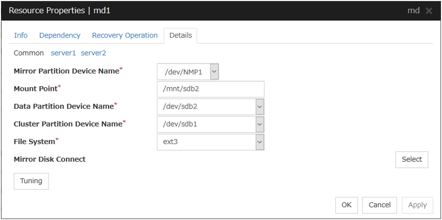
Mirror Partition Device Name
Select a mirror partition device name to be associated with the mirror partition.
Device names of mirror disk resource/hybrid disk resource that have already been configured are not displayed on the list.
Mount Point (Within 1023 bytes) Server Individual Setup
Specify a directory to mount the mirror partition device. The name should begin with "/."
Data Partition Device Name (Within 1023 bytes) Server Individual Setup
Specify a data partition device name to be used for a disk resource.
The name should begin with "/."
Cluster Partition Device Name (Within 1023 bytes) Server Individual Setup
Specify a cluster partition device name to be paired with the data partition.
The name should begin with "/."
File System
You select a file system type to be used on the mirror partition. Choose one from the list box. You may also directly enter the type.
ext3
ext4
xfs
none (no file system)
Mirror Disk Connect
Add, delete or modify mirror disk connects. In the Mirror Disk Connects list, I/F numbers of the mirror disk connects used for mirror disk resources are displayed.
In Available Mirror Disk Connect, mirror disk connect I/F numbers that are currently not used are displayed.
Set mirror disk connects on the Cluster Properties.
Maximum of two mirror disk connects can be used per mirror disk resource. For the behavior when two mirror disk connects are used, see "Mirror disk".
For details on how to configure mirror disk connects, see the "Installation and Configuration Guide".
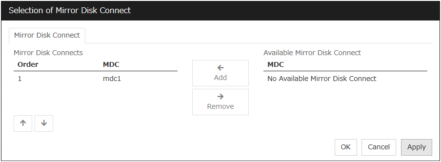
Add
Use Add to add a mirror disk connect. Select the I/F number you want to add from Available Mirror Disk Connect and then click Add. The selected number is added to the Mirror Disk Connects list.
Remove
Use Remove to remove mirror disk connects to be used. Select the I/F number you want to remove from the Mirror Disk Connect list and then click Remove. The selected number is added to Available Mirror Disk Connect.
Order
Use the arrows to change the priority of mirror disk connects to be used. Select the I/F number you want to change from the Mirror Disk Connect list and then click the arrows.
Tuning
Opens the Mirror Disk Resource Tuning Properties dialog box. You make detailed settings for the mirror disk resource there.
Mirror disk resource tuning properties
Mount tab
The advanced settings of mount are displayed.
This does not appear with none selected from File System under the Details tab of the Resource Properties dialog box.
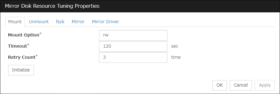
Mount Option (Within 1023 bytes)
Enter options to give the mount command when mounting the file system on the mirror partition device. Use a comma "," to separate multiple options.
Mount option example
Setting item
Setting value
Mirror partition device name
/dev/NMP5
Mirror mount point
/mnt/sdb5
File system
ext3
Mount option
rw,data=journal
The mount command to be run with the above settings is:
mount -t ext3 -o rw,data=journal /dev/NMP5 /mnt/sdb5
Timeout (1 to 999)
Enter how many seconds you want to wait for the mount command completion before its timeout when you mount the file system on the mirror partition device. Be careful about the value you specify. That is because it may take some time for the command to complete if the capacity of the file system is large.
Retry Count (0 to 999)
Enter how many times you want to retry to mount the file system on the mirror partition device when one fails. If you set this to zero (0), mount will not be retried.
Initialize
Clicking Initialize resets the values of all items to the default values.
Unmount tab
The advanced settings for unmounting are displayed.
This does not appear with none selected from File System under the Details tab of the Resource Properties dialog box.
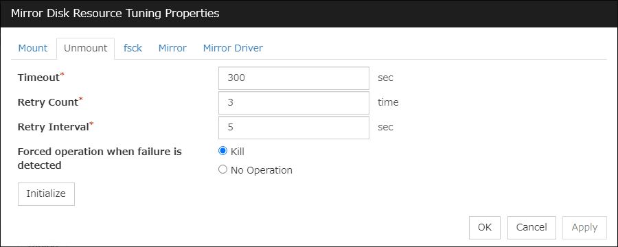
Timeout (1 to 999)
Enter how many seconds you want to wait for the unmount command completion before its timeout when you unmount the file system on the mirror partition device.
Retry Count (0 to 999)
Enter how many times you want to retry to unmount the file system on the mirror partition device when one fails. If you set this to zero (0), unmount will not be retried.
Retry Interval (0 to 999)
Enter the interval in which you want to retry unmounting the file system from the mirror partition device when unmounting fails.
Forced operation when failure is detected
Select an action to be taken at an unmount retry if unmount fails.
Initialize
Clicking Initialize resets the values of all items to the default values.
fsck tab
The advanced settings of fsck are displayed.
This does not appear with xfs or none selected from File System under the Details tab of the Resource Properties dialog box.
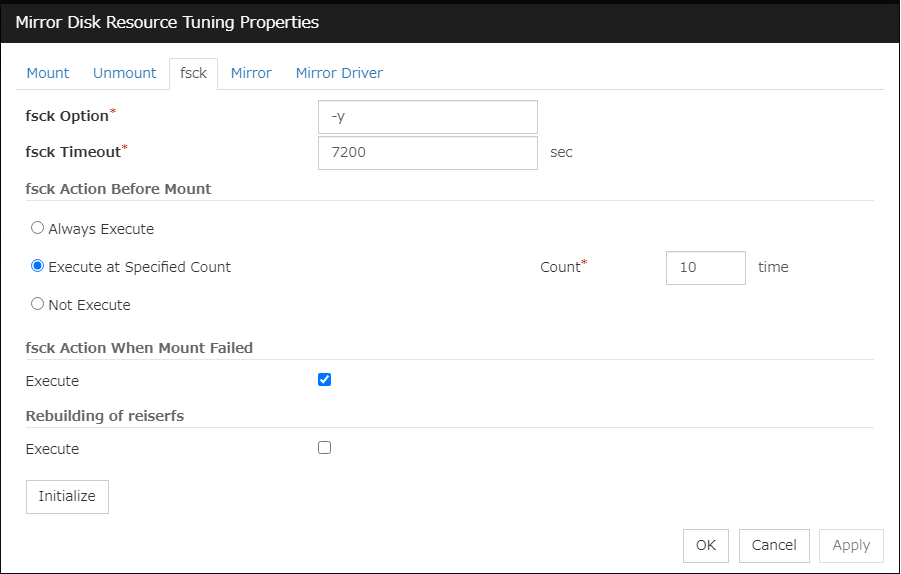
fsck Option (Within 1023 bytes)
Enter options to give the fsck command when checking the file system on the mirror partition device. Use a space to separate multiple options. Specify options so that the fsck command does not run interactively. Otherwise, activation of resources after the time specified to fsck Timeout elapses becomes an error.
fsck Timeout (1 to 9999)
Enter how many seconds you want to wait for the fsck command completion before its timeout when you check the file system on the mirror partition device. Be careful about the value you specify. This is because it may take some time for the command to complete if the capacity of the file system is large.
fsck Action Before Mount
Select an fsck action before mounting file system on a disk device from the following choices:
Note
The specified count for fsck is not related to the check interval managed by a file system.
fsck Action When Mount Failed
Set an fsck action to take when detecting a mount failure on a disk device.This setting is enabled when the setting of Mount Retry Count is other than zero.
Note
It is not recommended to set "Not Execute" fsck action before performing mount. With this setting, disk resource does not execute fsck and disk resource cannot be failed over when there is an error that can be recovered by fsck in the switchable partition.
Rebuilding of reiserfs
Specify the action when reiserfsck fails with a recoverable error.
Initialize
Clicking Initialize resets the values of all items to the default values.
xfs_repair tab
The detailed settings related to [xfs_repair] are displayed. The tab appears only if [xfs] is set for the file system.
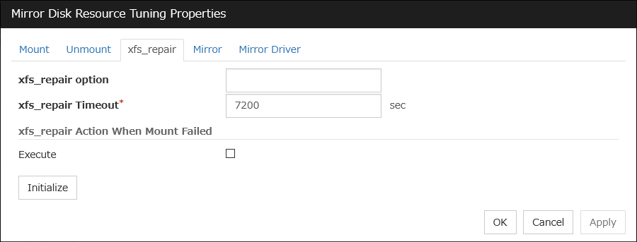
xfs_repair Option (Within 1023 bytes)
Enter the option to give to the [xfs_repair] command when checking the file system on the disk device. To enter multiple options, delimit each with a space.
xfs_repair Timeout (1 to 999)
Enter how many seconds you want to wait for the [xfs_repair] command completion before its timeout when you check the file system on the disk device. If the file system has a large size of disk space, it may take some time for the command to complete. Make sure that the value to set is not too small.
xfs_repair Action When Mount Failed
Set the [xfs_repair] action when mounting the file system on the disk device fails. This setting is enabled when the setting of Mount Retry Count is other than zero.
Initialize
Clicking Initialize resets the values of all items to the default values.
Mirror tab
The advanced settings of mirror disks are displayed.
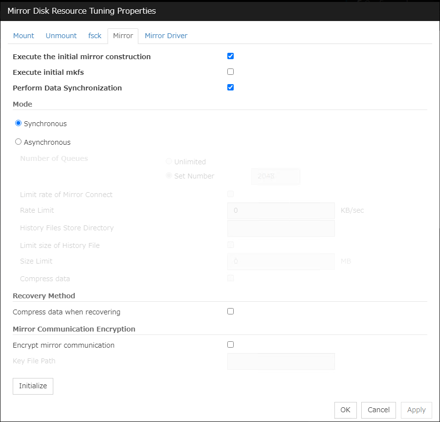
Execute the initial mirror construction
Specify if an initial mirror configuration is constructed when constructing a cluster.
The time that takes to construct the initial mirror is different from ext3/ext4 and other file systems.
Execute initial mkfs
Specify if an initial mkfs is constructed when constructing a cluster. This option can be set only if the initial mirror is being constructed.
In the case of hybrid disk resources, the clphdinit command behavior is executed instead of initial mkfs behavior upon cluster construction
Perform Data Synchronization
Specify if the mirror data synchronization is executed when mirror disk resource is activated.
Mode
Specify synchronous mode of mirror data.
When Asynchronous is selected, the Rate limitation of Mirror Connect check box can be selected.
With Asynchronous selected, you can edit the setting in the History File Store Directory text box to specify the directory of a file in which, if the maximum number of queues is exceeded, the excess is recorded. Without specifying the directory here, the file is generated under the following directory: (EXPRESSCLUSTER-installed directory)/work.
With Asynchronous selected, you can edit the setting in the Size Limitation of History File text box. When the accumulation in the history file reaches the size specified here, a mirror break occurs. Specifying the value as 0 or nothing makes the size unlimited.
When Asynchronous is selected, the Compress data check box can be selected.
Compress data when recovering
Specify whether to compress mirror recovery communication data.
Encrypt mirror communication
Choose whether to encrypt data passing through mirror disk connects. This setting affects both data for mirror synchronization and data for mirror recovery.
Key File Path (Within 1023 bytes)
For encrypting data flowing through mirror disk connects, be sure to specify the key file's full path here.
Note
The key file to be used is generated by using the openssl command of the OS.The following are examples for RHEL7. For a different distribution, check the openssl command options, which differ from those of RHEL7, before executing the command.# openssl rand 16 -out (key-file name) Generates a 16-byte (128-bit) encryption key. # openssl rand 24 -out (key-file name) Generates a 24-byte (192-bit) encryption key. # openssl rand 32 -out (key-file name) Generates a 32-byte (256-bit) encryption key.The applicable key length is 128, 192, or 256 bits.
Important
Be sure to use the same key file on all servers which can activate mirror disk resources. Using different key files leads to unsuccessful mirroring.
Initialize
Clicking Initialize resets the values of all items to the default values.
Mirror Driver tab
Advanced settings for a mirror driver is displayed.

Mirror Data Port Number (1 to 65535 6)
Set the TCP port number used for sending and receiving disk data between servers. The default value 29051 is set to the mirror disk resource or the hybrid disk resource created first. From a second mirror disk resource or the hybrid disk resource, the value increased by one from default (29052,29053,...) is set accordingly.
- 6
It is not recommended to use well-known ports, especially reserved ports from 1 to 1023.
Heartbeat Port Number (1 to 65535 7)
Set the port number that a mirror driver uses to communicate control data between servers. The default value 29031 is set to the mirror disk resource or the hybrid disk resource created first. From a second mirror disk resource or the hybrid disk resource, the value increased by one from default (29032, 29033,...) is set accordingly.
- 7
It is not recommended to use well-known ports, especially reserved ports from 1 to 1023.
ACK2 Port Number (1 to 65535 8)
Set the port number that a mirror driver uses to communicate control data between servers. The default value 29071 is set to the mirror disk resource or the hybrid disk resource created first. From a second mirror disk resource or the hybrid disk resource, the value increased by one from default (29072, 29073,...) is set accordingly.
- 8
It is not recommended to use well-known ports, especially reserved ports from 1 to 1023.
Send Timeout (10 to 99)
Set the delivery time-out for write data.
Connection Timeout (5 to 99)
Set the time-out for connection.
Ack Timeout (1 to 600)
Set the time-out which waits for Ack response when mirror recovers and data is synchronized.
Receive Timeout (1 to 600)
Set the receive time-out for write confirmation.
Heartbeat interval (1 to 600)
Set the heartbeat interval between mirror disk connects by the mirror driver.
ICMP Echo Reply Reception Timeout (1 to 100)
Set the heartbeat timeout between mirror disk connects by the mirror driver. If no-response is returned for the ICMP Echo Request retry count during the time set here, a mirror disk connect disconnection is assumed.
ICMP Echo Request Retry Count (1 to 50)
Set the heartbeat retry count between mirror disk connects by the mirror driver. This value is related to the mirror connect disconnection judgment sensitivity as well as the ICMP Echo Reply receive timeout.
Initialize
Clicking Initialize resets the following values to the default values.
Send Timeout
Connection Timeout
Ack Timeout
Receive Timeout
Heartbeat Interval
ICMP Echo Reply Receive Timeout
ICMP Echo Request Retry Count
Note
For Mirror Data Port Number, Heartbeat Port Number and ACK2 Port Number, different port numbers should be configured for each resource. Also, those should not be the same as other port numbers used on a cluster. Thus, the initial values are not set even when you click Initialize.
3.11. Understanding Hybrid disk resources
3.11.1. Dependencies of Hybrid disk resource
By default, this function depends on the following group resource types.
Group resource type |
|---|
Floating IP resource |
Virtual IP resource |
AWS Elastic IP resource |
AWS Virtual IP resource |
AWS Secondary IP resource |
3.11.2. What is hybrid disk?
A hybrid disk is a resource which performs data mirroring between two server groups. A server group consists of 1 server or 2 servers. When a server group consists of 2 servers, a shared disk is used. When a server group consists of 1 server, a disk which is not shared type (e.g. a built-in disk, an external disk chassis which is not shared between servers) is used.
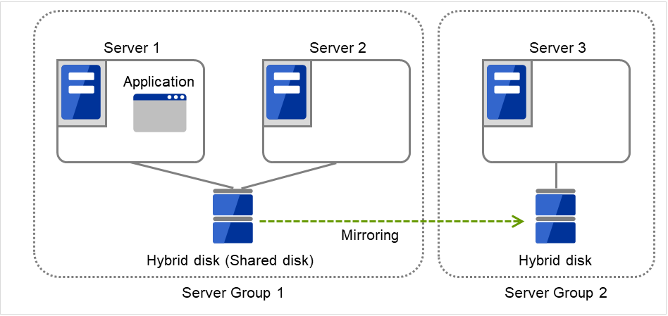
Fig. 3.109 Hybrid configuration (1): in a normal case
When Server 1 crashes, the application is failed over to Server 2.
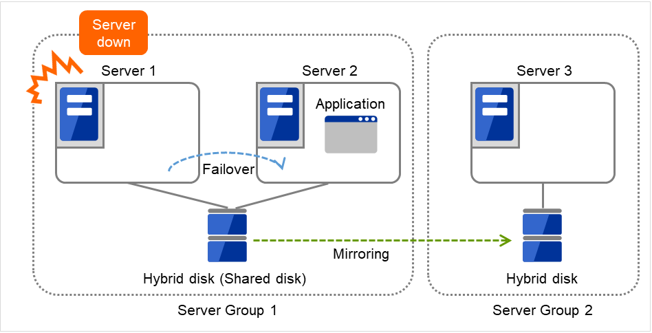
Fig. 3.110 Hybrid configuration (2): Server 1 crashes
When Server 2 crashes, the application is failed over to Server 3.
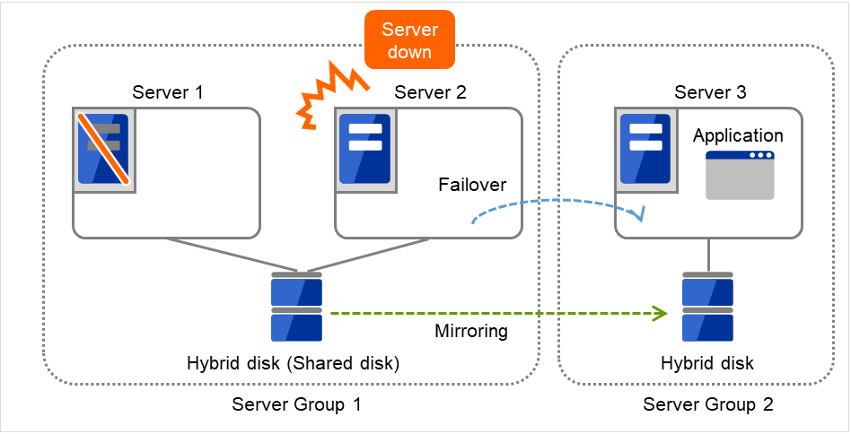
Fig. 3.111 Hybrid configuration (3): Server 2 crashes
Data partition
Partitions where data to be mirrored (such as application data) is stored are referred to as data partitions.
Allocate data partitions as follows:
- Data partition sizeThe size of data partition should be 1GB or larger but smaller than 1TB.(Less than 1TB size is recommended from the viewpoint of the construction time and the restoration time of data.)
- Partition ID83(Linux)
- Please make the file system on data partitions if you need. Automatic initial mkfs is not executed.
- EXPRESSCLUSTER is responsible for the access control (mount/umount) of file system. Do not configure the settings that allow the OS to mount or unmount a data partition.
Cluster partition
Dedicated partitions used in EXPRESSCLUSTER for controlling hybrid disk are referred to as cluster partition.
Allocate cluster partitions as follows:
- Cluster partition size1024MiB or more. Depending on the geometry, the size may be larger than 1024MB but that is not a problem.
- Partition ID83(Linux)
A cluster partition and data partition for data mirroring should be allocated in a pair.
Do not make the file system on cluster partitions.
Mirror Partition Device (/dev/NMPx)
One hybrid disk resource provides the file system of the OS with one mirror partition. If a hybrid disk resource is registered with the failover group, it can be accessed only from one server (it is generally the primary server of the resource group).
Typically, the mirror partition device (dev/NMPx) remains transparent to users (AP) because I/O is performed via a file system. When the information is created by the Cluster WebUI, device names should be assigned without overlapping with each other.
- EXPRESSCLUSTER is responsible for the access control (mount/umount) of file system. Do not configure the settings that allow the OS to mount or unmount a data partition.Mirror partition's (hybrid disk resource's) accessibility to applications is the same as switching partition (disk resources) that uses shared disks.
Mirror partition switching is performed on a failover group basis according to the failover policy.
/dev/NMPx(x is a number between 1 and 8) is used for the special device name of mirror partition. Do not use /dev/NMPx in other device drivers.
- The major number 218 is used for mirror partition. Do not use the major number 218 in other device drivers.
Example 1) When two servers use the shared disk and the third server uses the built-in disk
The following figure illustrates an example of hybrid configuration: Servers 1 and 2 share a disk, on which the cluster partition's content and the data partition's content are mirrored in a disk connected to Server 3.The cluster partition and data partition, a unit of failover in a hybrid resource, is a mirror partition device.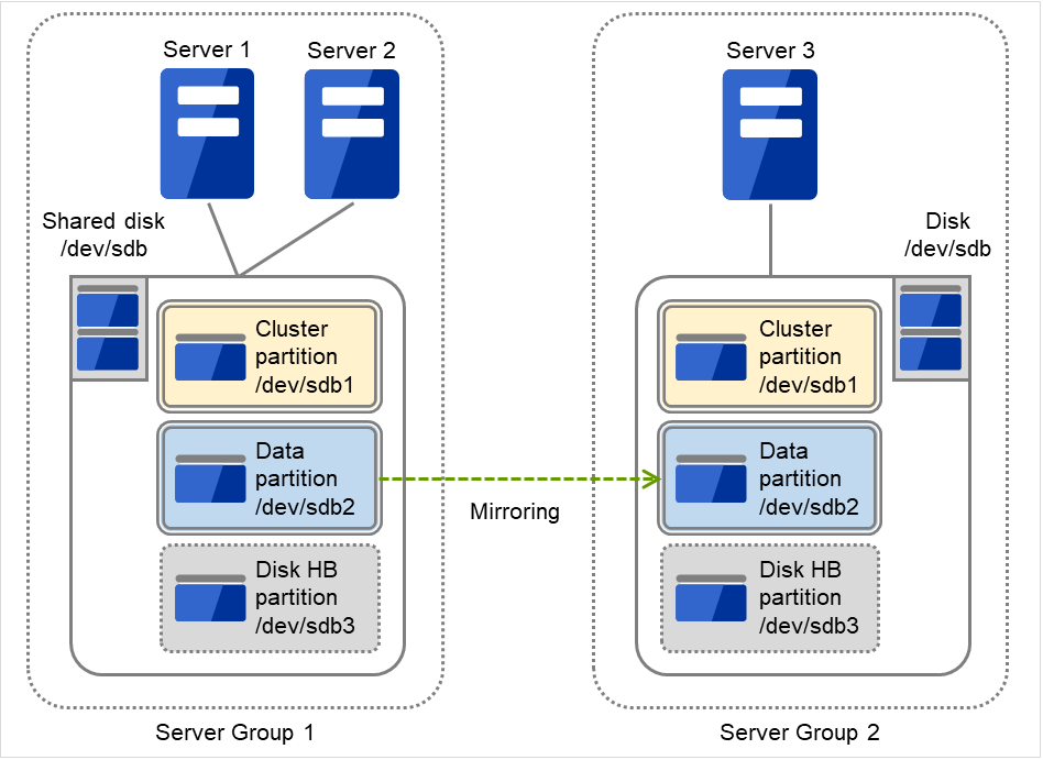
Fig. 3.112 Partitions in hybrid configuration
When a non-shared disk is used (i.e. when there is one server in the server group), it is possible to secure a partition for the hybrid disk resource (cluster partition and data partition) on the same disk where the OS (root partition and swap partition) is located.
- When maintainability at a failure is important:It is recommended to allocate a disk for mirror which is not used by the OS (such as root partition, swap partition).
- If LUN cannot be added due to H/W RAID specifications:If you are using hardware/RAID preinstall model where the LUN configuration cannot be changed, you can allocate a mirror partition (cluster partition, data partition) in the disk where the OS (root partition, swap partition) is located.
Mirror disk connect
See "Mirror disk connect" for the "Mirror disk"
3.11.3. Mirror parameter settings
The following parameters are the same as those of mirror disk resources. See "mirror disk resources".
Mirror data port number
Heartbeat port number
ACK2 port number
The maximum number of request queues
Connection timeout
Send timeout
Receiving timeout
Ack timeout
Difference bitmap update interval (cluster properties)
Difference Bitmap size (cluster properties)
Mirror agent send timeout (cluster properties)
Mirror agent receiving timeout (cluster properties)
Recovery data size (cluster properties)
Initial mirror construction
Number of Queues
Mode of Communication Band
History File Store Directory
Size Limitation of History File
Heartbeat Interval
ICMP Echo Reply Receive Timeout
ICMP Echo Request Retry Count
Key File Path
The following parameter is different from mirror disk resource.
- Initial mkfsAutomatic initial mkfs is not executed. Please execute mkfs manually.
3.11.4. Notes on hybrid disk resources
If device names for the cluster partitions or the data partitions differ between servers, set up each server separately. In addition, if the device names differ between servers belonging to the same server group, set by-id to the device name.
With Exclude Mount/Unmount Commands checked in the Extension tab of Cluster Properties, activating/deactivating a hybrid disk resource may take time. This is because the mounting/unmounting of a disk resource, mirror disk resource, or hybrid disk resource is performed exclusively in the same server.
- When specifying path including symbolic link for mount point, Force Operation cannot be done even if it is chosen as operation in failure detection.Similarly, if a path containing "//" is specified, forced termination will also fail.
Disks using stripe set, volume set, mirroring, stripe set with parity by Linux md cannot be specified for the cluster partition and data partition.
Hybrid disk resources (mirror partition devices) cannot be the targets of stripe set, volume set, mirroring, stripe set with parity by Linux md or LVM.
- When the geometries of the disks used as hybrid disks differ between the servers:The size of a partition allocated by the fdisk command is aligned by the number of blocks (units) per cylinder. Allocate data partitions to achieve the following data partition size and direction of the initial mirror construction.
Source server <= Destination server
"Source server" refers to the server with the higher failover policy in the failover group to which a hybrid disk resource belongs."Destination server" refers to the server with the lower failover policy in the failover group to which a hybrid disk resource belongs.If the data partition sizes differ significantly between the copy source and the copy destination, initial mirror construction may fail. Be careful, therefore, to secure data partitions of similar sizes.Make sure that the data partition sizes do not cross over 32GiB, 64GiB, 96GiB, and so on (multiples of 32GiB) on the source server and the destination server. For sizes that cross over multiples of 32GiB, initial mirror construction may fail.
Examples)
Combination
Data partition size
Description
On server 1
On server 2
OK
30GiB
31GiB
OK because both are in the range of 0 to 32GiB.
OK
50GiB
60GiB
OK because both are in the range of 32GiB to 64GiB.
NG
30GiB
39GiB
Error because they are crossing over 32GiB.
NG
60GiB
70GiB
Error because they are crossing over 64GiB.
- Do not use the O_DIRECT flag of the open() system call for a file used in a hybrid disk resource.Examples include the Oracle parameter filesystemio_options = setall.
Do not specify a mirror partition device (such as /dev/NMP1) as the monitor target in the READ (O_DIRECT) disk monitoring mode.
For a cluster configuration that uses a hybrid disk, do not set the final action of a monitor resource, etc., to Stop the cluster service.
For the data partition and the cluster partition of hybrid disk resources, use disk devices with the same logical sector size on all servers. If you use devices with different logical sector sizes, they do not operate normally. They can operate even if they have different sizes for the data partition and the cluster partition.
Examples)
Combination
Logical sector size of the partition
Description
Server 1
Server 1
Server 2
Server 2
OK
512B
512B
512B
512B
The logical sector sizes are uniform.
OK
4KB
512B
4KB
512B
NG
4KB
512B
512B
512B
The logical sector sizes for the data partitions are not uniform.
NG
4KB
4KB
4KB
512B
The logical sector sizes for the cluster partitions are not uniform.
Do not use HDDs and SSDs in combination for the disks used for the data partition and the cluster partition of hybrid disk resources. If you used them in combination, optimum performance cannot be obtained. Even if disks with different disk types are used for the data partition and the cluster partition, they can operate.
Examples)
Combination
Logical sector size of the partition
Description
Server 1
Server 1
Server 2
Server 2
OK
HDD
HDD
HDD
HDD
The disk types are uniform.
OK
SSD
HDD
SSD
HDD
NG
SSD
HDD
HDD
HDD
As the data partitions, both HDD and SSD are used.
NG
SSD
SSD
SSD
HDD
As the cluster partitions, both HDD and SSD are used.
Behavior of mirror recovery after the active server goes down abnormally
When the active server goes down abnormally, depending on the timing of the server failure, full mirror recovery or differential mirror recovery is performed.
When a resource is activated by a server connected via a shared disk (a server in the same server group)
The following figure illustrates an example of hybrid configuration: Servers 1 and 2 share a disk, on which the cluster partition's content and the data partition's content are mirrored in a disk connected to Server 3.
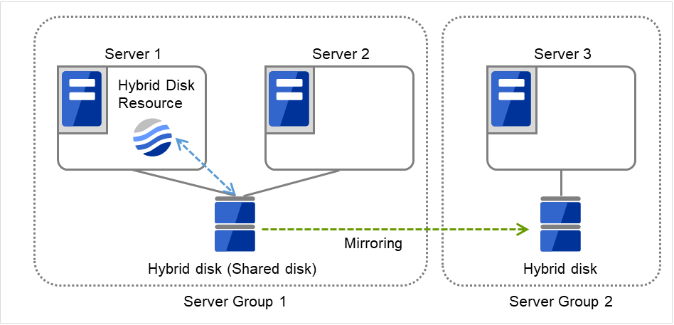
Fig. 3.113 Hybrid configuration--resource activation within the same server group (1): in a normal case
When Server 1 crashes, the hybrid disk resource is failed over to Server 2.
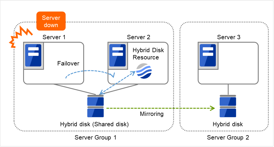
Fig. 3.114 Hybrid configuration--resource activation within the same server group (2): Server 1 crashes
If mirror recovery is required between the shared disk and the Server-3-connected disk, the process varies depending on when Server 1 crashes:
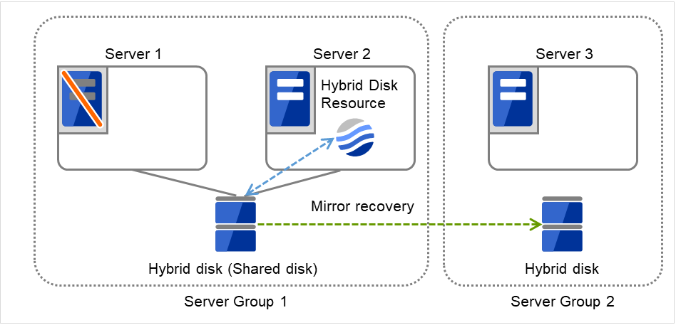
Fig. 3.115 Hybrid configuration--resource activation within the same server group (3): mirror recovery after Server 1 crashes
When a resource is activated by a server in the remote server group
The following figure illustrates an example of hybrid configuration: Servers 1 and 2 share a disk, on which the cluster partition's content and the data partition's content are mirrored in a disk connected to Server 3.

Fig. 3.116 Hybrid configuration--resource activation within the remote server group (1): in a normal case
When Server 1 crashes, the hybrid disk resource is failed over to Server 3.
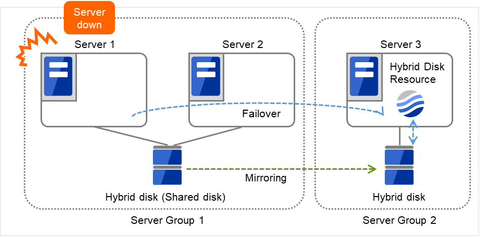
Fig. 3.117 Hybrid configuration--resource activation within the remote server group (2): Server 1 crashes
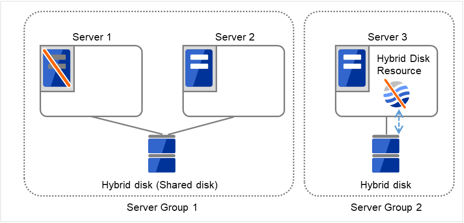
Fig. 3.118 Hybrid configuration--resource activation within the remote server group (3): mirror recovery after Server 1 crashes
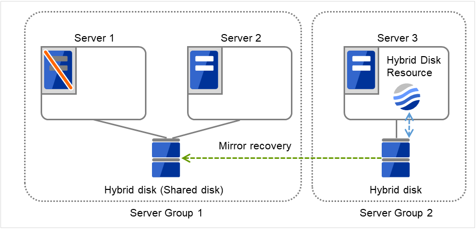
Fig. 3.119 Hybrid configuration--resource activation within the remote server group (4): mirror recovery after Server 1 crashes
3.11.5. mount processing flow
The mount processing needed to activate the hybrid disk resource is performed as follows:
With none specified for the file system, the mount processing does not occur.
Is the device already mounted?
When already mounted -> To X
Is fsck set to be run before mounting?
Timing at which to run fsck -> Run fsck for the device.
Mount the device.
Mounted successfully -> To O
Is mounting set to be retried?
When retry is not set -> To X
When fsck(xfs_repair) is set to be run if mounting fails:
When fsck is executed in 2. and mount is successful -> Go to 6.
When mount fails in 3. due to a timeout -> Go to 6.
Other than the above -> Execute fsck(xfs_repair) for the device.
Retry mounting of the device.
Mounted successfully -> To O
Has the retry count for mounting been exceeded?
Within the retry count -> Go to 6.
The retry count has been exceeded -> To X
O The resource is activated (mounted successfully).
X The resource activation has failed (not mounted).
3.11.6. umount processing flow
The umount processing to deactivate the hybrid disk resource is performed as follows:
With none specified for the file system, the umount processing does not occur.
Is the device already unmounted?
When already unmounted -> To X
Unmount the device.
Unmounted successfully -> To O
Is unmount set to be retried?
When retry is not set -> To X
Is the device still mounted? (Is the mount point removed from the mount list and is the mirror device in the unused status?)
No longer mounted -> To O
Try KILL for the process using the mount point.
Retry unmount of the device.
Unmounted successfully -> To O
Is the result other than the unmount timeout and is the mount point removed from the mount list?
The mount point has already been removed.
-> Wait until the mirror device is no longer used.
(Wait no more than a length of time equal to the unmount timeout.)
Has the retry count for unmount been exceeded?
Within the retry count -> Go to 4.
The retry count is exceeded -> To X
O The resource is stopped (unmounted successfully).
X The resource stop has failed (still mounted, or already unmounted).
3.11.7. Details tab
The followings are the same as those of mirror disk resources. Refer to "mirror disk resource".
Hybrid disk detail tab (See mirror disk detail tab)
Mirror disk connect selection
Hybrid disk adjustment properties (See mirror disk adjustment properties)
Mount tab
Unmount tab
fsck tab
xfs_repair tab
Mirror tab (parameter other than the one for executing the initial mkfs)
Mirror drive tab
The following tab is different from that of mirror disk resource:
Mirror tab of hybrid disk adjustment properties [execute initial mkfs]
Execute initial mkfs
The hybrid disk resource in this version, automatic initial mkfs is not executed.
3.12. Understanding Volume manager resources
3.12.1. Dependencies of Volume manager resources
The volume manager resources depend on the following group resource types by default.
Group resource type |
|---|
Dynamic DNS resource |
Floating IP resource |
Virtual IP resource |
AWS Elastic IP resource |
AWS Virtual IP resource |
AWS Secondary IP resource |
AWS DNS resource |
Azure DNS resource |
3.12.2. What is a Volume manager resource?
The volume manager is disk management software that handles multiple storage devices and disks as one logical disk.
Volume manager resources control logical disks managed by the volume manager.
If data necessary for operation is stored in a logical disk, it is automatically taken over, for example, when there is a failover or a failover group is moved.
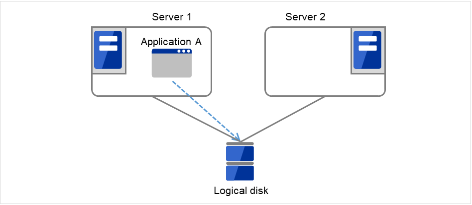
Fig. 3.120 Volume manager resource (1)
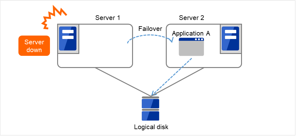
Fig. 3.121 Volume manager resource (2)
3.12.3. Notes on Volume manager resources
<General>
Do not use volume manager resources to manage a mirror disk.
Disk resources control each volume.
Do not specify the import or export settings on the OS because EXPRESSCLUSTER performs access control (importing or exporting) for logical disks.
<Notes on using resources with the volume manager lvm>
Volume groups are not defined on the EXPRESSCLUSTER side.
At least one disk resource is required because each volume must be controlled.
The volume groups included in the EXPRESSCLUSTER configuration data are automatically exported when the OS is started.
Other volume groups are not exported.
When a volume group created by using a shared disk is specified as a target volume, the import/export status of the volume group is recorded on the shared disk according to the LVM specification. Therefore, if activation (import) or deactivation (export) is performed on the active server, it might be assumed that the same operation is performed on the standby server.
When controlling the LVM by using the volume manager resource in an environment of Red Hat Enterprise Linux 7 or later, the LVM metadata daemon must be disabled.
Run the following commands when activating resource.
Command
Option
Timing when using command
vgs
-P
Verifying volume group status
--noheadings
Verifying volume group status
-o vg_attr,vg_name
Verifying volume group status
vgimport
(Nothing)
Importing volume group
vgscan
(Nothing)
Scanning volume group
vgchange
-ay
Activating volume group
The resource activation sequence is shown below.

Fig. 3.122 Resource activation sequence (lvm)
Perform the command for verifying the volume group status. Its failure means that in the activation.
vgs -P --noheadings -o vg_attr, vg_name Volume group name
Perform the command for importing the volume group. Its failure means that in the activation.
vgimport Volume group name
Perform the command for scanning the volume group.
vgscanPerform the command for activating the volume group. Its success means that in the activation; its failure means that in the activation.
vgchange -ay Volume group name
Run the following commands when deactivating resource.
Command
Option
Timing when using command
vgs
-P
Verifying volume group status
--noheadings
Verifying volume group status
-o vg_attr,vg_name
Verifying volume group status
vgchange
-an
Deactivating volume group
vgexport
(Nothing)
Exporting volume group
The resource deactivation sequence is shown below.
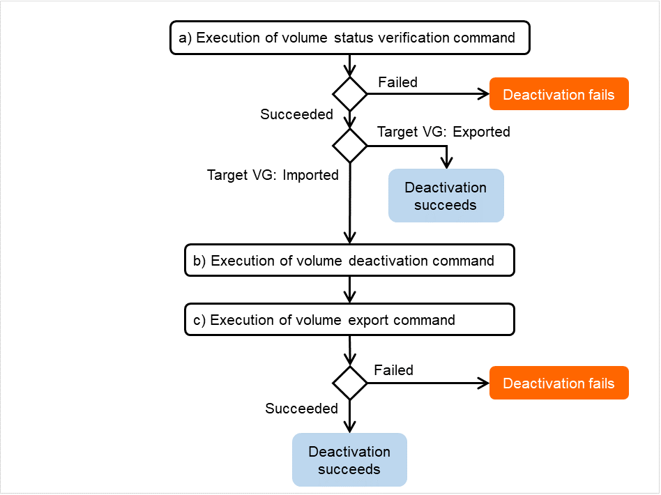
Fig. 3.123 Resource deactivation sequence (lvm)
- Perform the command for verifying the volume group status. Its failure means that in the deactivation.The success in the execution means that in the deactivation, if the target volume group is found ready for export .
vgs -P --noheadings -o vg_attr, vg_name Volume group name
Perform the command for deactivating the volume group. Its failure means that in the deactivation.
vgchange -an Volume group name
Perform the command for exporting the volume group. Its success means that in the deactivation; its failure means that in the deactivation.
vgexport Volume group name
<Notes on using resources with the volume manager zfspool>
- Exporting and other processes for ZFS may be delayed dramatically if iSCSI connection is disconnected when using ZFS storage pool under iSCSI environment.(OS restriction)The ZFS operations at the time of iSCSI disconnection is regulated in ZFS property value failmode. However, failmode=panic is recommended in EXPRESSCLUSTER. When it is failmode=panic, it operates as OS panics independently in a given time after iSCSI
- On the data set that the ZFS property value mountpoint is configured in legacy, the file system will not be mounted by just importing the storage pool. In this case, it is necessary to mount or unmount ZFS file system by using the disk resource in addition to Volume Manager resource.
- When on Ubuntu Server 16.04 or later, a failover group may be activated on more than 1 servers, state of "network partition" in other words, depending on the timing of OS startup. Even if the storage pool is automatically imported at OS startup, prevent the file system from being automatically mounted.The way to avoid automatic mounting is either of the below.
Set ZFS property value mountpoint to legacy.
Set ZFS property value canmount to noauto.
This setting enables to avoid the automatic mounting even when the automatic import is performed at OS startup, preventing the network partition. In this case, it is necessary to mount or unmount ZFS file system by using the disk resource.
3.12.4. Details tab
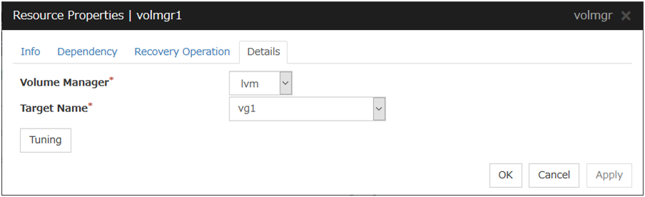
Volume Manager
Specify the volume manager to use. The following volume managers can be selected:
lvm (LVM volume group control)
zfspool (ZFS storage pool control)
Target Name (within 1023 bytes)
Specify the volume name in the <VG name> format (only the target name is used).
Combo box options collect volume group information from all the servers and display all the volume groups on one or more servers.
When the volume manager is lvm, it's possible to control multiple volumes together. More than one volume is delimited with an one-byte space.
Tuning
This displays the Volume Manager Resource Tuning Properties dialog box. Specify detailed settings for the volume manager resource.
Volume Manager Resource Tuning Properties (When Volume Manager is other than [zfspool])
Import Tab
The detailed import settings are displayed.
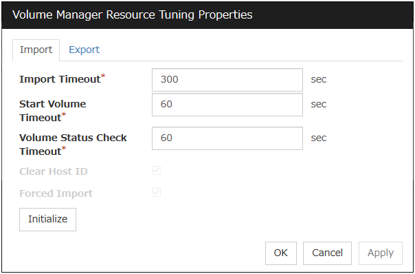
Import Timeout (1 to 9999)
Specify how long the system waits for completion of the volume import command before it times out.
Start Volume Timeout (1 to 9999)
Specify the startup command timeout.
Volume Status Check Timeout (1 to 9999)
Specify the volume status check command timeout.
This option can be used when the volume manager is lvm.
Initialize
Clicking Initialize resets the values of all items to the defaults.
Export Tab
The detailed export settings are displayed.
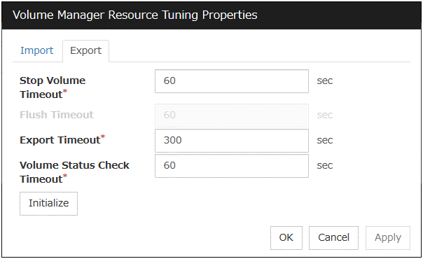
Stop Volume Timeout (1 to 9999)
Specify the volume deactivation command timeout.
Export Timeout (1 to 9999)
Specify the export/deport command timeout.
Volume Status Check Timeout (1 to 9999)
Specify the volume status check command timeout.
This option can be used when the volume manager is lvm.
Initialize
Clicking Initialize resets the values of all items to the defaults.
Volume Manager Resource Tuning Properties (When Volume Manager is [zfspool])
Import Tab
The detailed import settings are displayed.
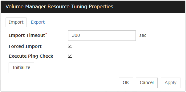
Import Timeout (1 to 9999)
Specify how long the system waits for completion of the volume import command before it times out.
Forced Import
Specify whether to forcibly import data when importing fails. Data is forcibly imported if the check box is selected.
Execute Ping Check
This setting is enabled only when Forced Import is set to ON.
If an import failure occurs because another host has already performed import, ping Check specifies monitoring of whether the host is active using ping before the forced import. If the host becomes active as a result of the monitoring, forced activation is not performed. This prevents more than one host from simultaneously performing import to a single pool. When the check box is ON, activation of the host is monitored.
Note
When this setting is enabled, and a considerable time elapses between EXPRESSCLUSTER stopping and the OS shutting down, failover may fail. For example, if a monitor resource detects an abnormality and shuts down the operating server, and if the standby system starts activation of the volume manager before the operating server has stopped, a ping check will cause the activation to fail.
Initialize
Clicking Initialize resets the values of all items to the defaults.
Export Tab
The detailed export settings are displayed.
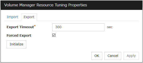
Export Timeout (1 to 9999)
Specify how long the system waits for completion of the volume export command before it times out.
Forced Export
Specify whether to forcibly export data when exporting fails. Data is forcibly exported if the check box is selected.
Initialize
Clicking Initialize resets the values of all items to the defaults.
3.13. Understanding Dynamic DNS resources
3.13.1. Dependencies of Dynamic DNS resources
By default, this function depends on the following group resource types:
Group resource type |
|---|
Virtual IP resource |
Floating IP resource |
AWS Elastic IP resource |
AWS Virtual IP resource |
AWS Secondary IP resource |
3.13.2. What is a Dynamic DNS resource?
A Dynamic DNS resource registers the virtual host name and the IP address of the active server to the Dynamic DNS server. Client applications can be connected to a cluster server by using a virtual computer name. When the virtual host name is used, the client does not have to be aware of whether the connection destination server is switched when a failover occurs or a group is moved.
The following figure shows the Dynamic DNS server (DDNS server), Servers 1 and 2, and a client. On the DDNS server, Server 1 registers the virtual host name and the IP address.
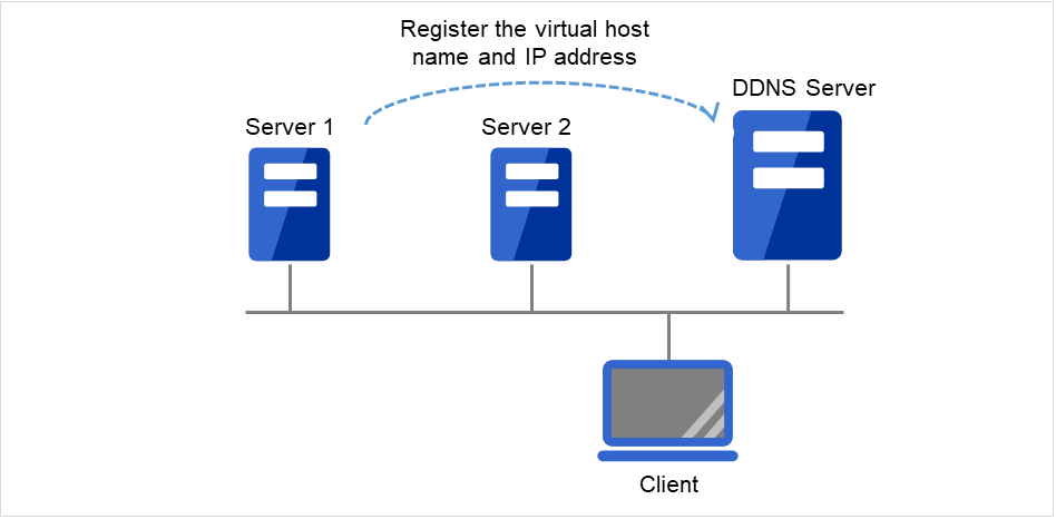
Fig. 3.124 Configuration with the DDNS server (1)
The client queries the DDNS server about the IP address (corresponding to the virtual host name) to be accessed. The DDNS server returns the IP address (corresponding to the virtual host name) of Server 1 to the client. The client then accesses the IP address of the virtual host name.
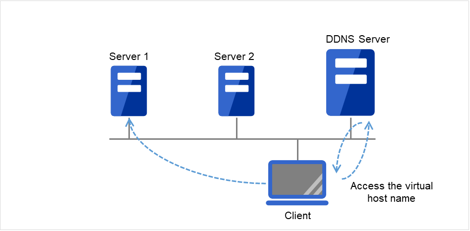
Fig. 3.125 Configuration with the DDNS server (2)
Server 1 crashes, and a failover to Server 2 occurs.
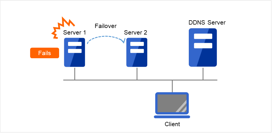
Fig. 3.126 Configuration with the DDNS server (3)
On the DDNS server, Server 2 registers the virtual host name and the IP address.
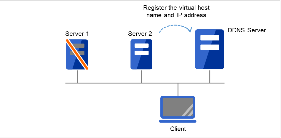
Fig. 3.127 Configuration with the DDNS server (4)
The client queries the DDNS server about the IP address (corresponding to the virtual host name) to be accessed. The DDNS server returns the IP address (corresponding to the virtual host name) of Server 2 to the client. The client then accesses the IP address of the virtual host name.
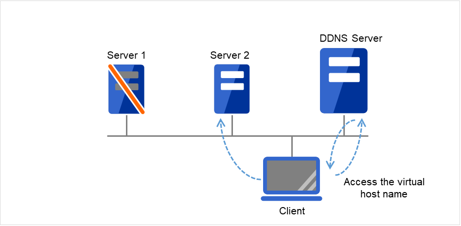
Fig. 3.128 Configuration with the DDNS server (5)
3.13.3. Preparing to use Dynamic DNS resources
Set up the DDNS server before using Dynamic DNS resources.
The description below assumes the use of BIND9.
When using Dynamic DNS resources with authentication
Create a shared key on the BIND9 server by using the dnssec-keygen command. Add the shared key to /etc/named.conf and allow the zone file to be updated. When adding a Dynamic DNS resource, enter the shared key name in Authentication Key Name and the shared key value in Authentication Key Value.
Note
For details about setting up the DDNS server, using the dnssec-keygen command, and specifying setting other than allow-update, see the BIND manual.
Example:
- Generate a shared key.#dnssec-keygen -a HMAC-MD5 -b 256 -n HOST exampleexample is the shared key name.
When the dnssec-keygen command is executed, the two files below are generated. The same shared key is used for these files.
Kexample.+157+09088.keyKexample.+157+09088.privateWhile the shared key is extracted from Kexample.+157+09088.key when using the named.conf setting below, using Kexample.+157+09088.private leads to the same result.The shared key value for Kexample.+157+09088.key is underlined below.# cat Kexample.+157+09088.keyexample. IN KEY 512 3 157 iuBgSUEIBjQUKNJ36NocAgaB Add the shared key information to /etc/named.conf.
key " example " {
    algorithm hmac-md5;
    secret " iuBgSUEIBjQUKNJ36NocAgaB";
};
Add the shared key information to the zone statement in /etc/named.conf.
zone "example.jp" {
    :
    allow-update{
         key example;
    };
    :
};
When adding a Dynamic DNS resource by using the Cluster WebUI, enter the shared key name (example) in Authentication Key Name and the shared key value (iuBgSUEIBjQUKNJ36NocAgaB) in Authentication Key Value.
When using Dynamic DNS resources without authentication
Be sure to specify the IP addresses of all servers in the cluster as the IP address range in which the zone file can be updated (allow-update {xxx.xxx.xxx.xxx}) in /etc/named.conf.
Example:
IP address for Server 1 in the cluster: 192.168.10.110IP address for Server 2 in the cluster: 192.168.10.111Add the IP address range in which updates are allowed to the zone statement in /etc/named.conf.
zone "example.jp" {
    :
    //IP address range in which updates are allowed
    allow-update {
        192.168.10.0/24;
    };
    :
};
or
zone "example.jp" {
    :
    //IP address range in which updates are allowed
    allow-update {
        192.168.10.110;
        192.168.10.111;
    };
    :
};
When adding a Dynamic DNS resource, do not enter any values in Authentication Key Name or Authentication Key Value.
3.13.4. Notes on Dynamic DNS resources
When using Dynamic DNS resources, the bind-utils package is necessary on each server.
Each server must be able to resolve the virtual host name.
When IP address of each server exists in different segments, FIP address cannot be set as IP address of Dynamic DNS resources.
To register each server IP address with the DDNS server, specify the addresses in the settings for each server.
In case of connecting from clients using virtual host name, when the fail over of the group which has Dynamic DNS resources occurs, reconnection may be necessary (restart browsers, etc.).
This method, which authenticates resources, applies only to a DDNS server set up using BIND9. To use the method without authentication, do not enter any values in Authentication Key Name or Authentication Key Value.
The behavior when the Cluster WebUI is connected depends on the Dynamic DNS resource settings.
- When the IP address of each server is specified for Dynamic DNS resources on a server basisIf the Cluster WebUI is connected by using the virtual host name from the client, this connection is not automatically switched if a failover occurs for a group containing Dynamic DNS resources.To switch the connection, restart the browser, and then connect to the Cluster WebUI again.
- When the FIP address is specified for the Dynamic DNS resourceIf the Cluster WebUI is connected by using the virtual host name from the client, this connection is automatically switched if a failover occurs for a group containing Dynamic DNS resources.
- If Dynamic DNS resources are used with the method with authentication, the difference between the time of every server in the cluster and that of the DDNS server must be less than five minutes.If the time difference is five minutes or more, the virtual host name cannot be registered with the DDNS server.
3.13.5. Details tab
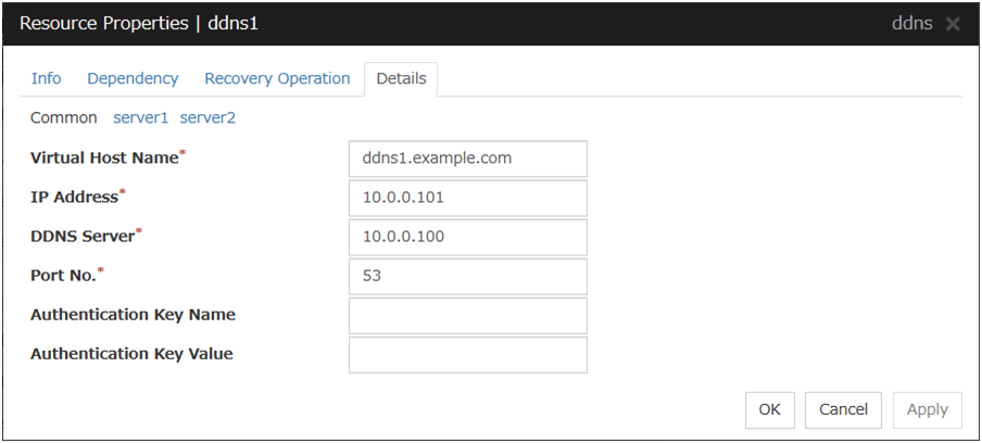
Virtual Host Name
Enter the virtual host name to register with the DDNS service.
IP Address Server Individual Setup
Enter the IP address for the virtual host name.When also using FIP resources, enter the IP address of the resources on the Common tab.When using an IP address for each server, enter the IP address on each server tab.
DDNS Server
Enter the IP address of the DDNS server.
Port No.
Enter the port number of the DDNS server. The default value is 53.
Authentication Key Name
Enter the shared key name if a shared key was generated using the dnssec-keygen command.
Authentication Key Value
Enter the value of the shared key generated using the dnssec-keygen command.
3.14. Understanding AWS Elastic IP resources
3.14.1. Dependencies of AWS Elastic IP resources
By default, this function does not depend on any group resource type.
3.14.2. What is an AWS Elastic IP resource?
Client applications can use AWS Elastic IP addresses(referred to as the EIP) to access the Amazon Virtual Private Cloud (referred to as the VPC) in the Amazon Web Services (referred to as AWS) environment.
By using EIP, clients do not need to be aware of switching access destination server when a failover occurs or moving a group migration.
HA cluster with EIP control
This is used to place instances on public subnets (release business operations inside the VPC).
A configuration such as the following is assumed: Instances to be clustered are placed on public subnets in each Availability Zone (referred to as AZ), and each instance can access the Internet via the gateway.
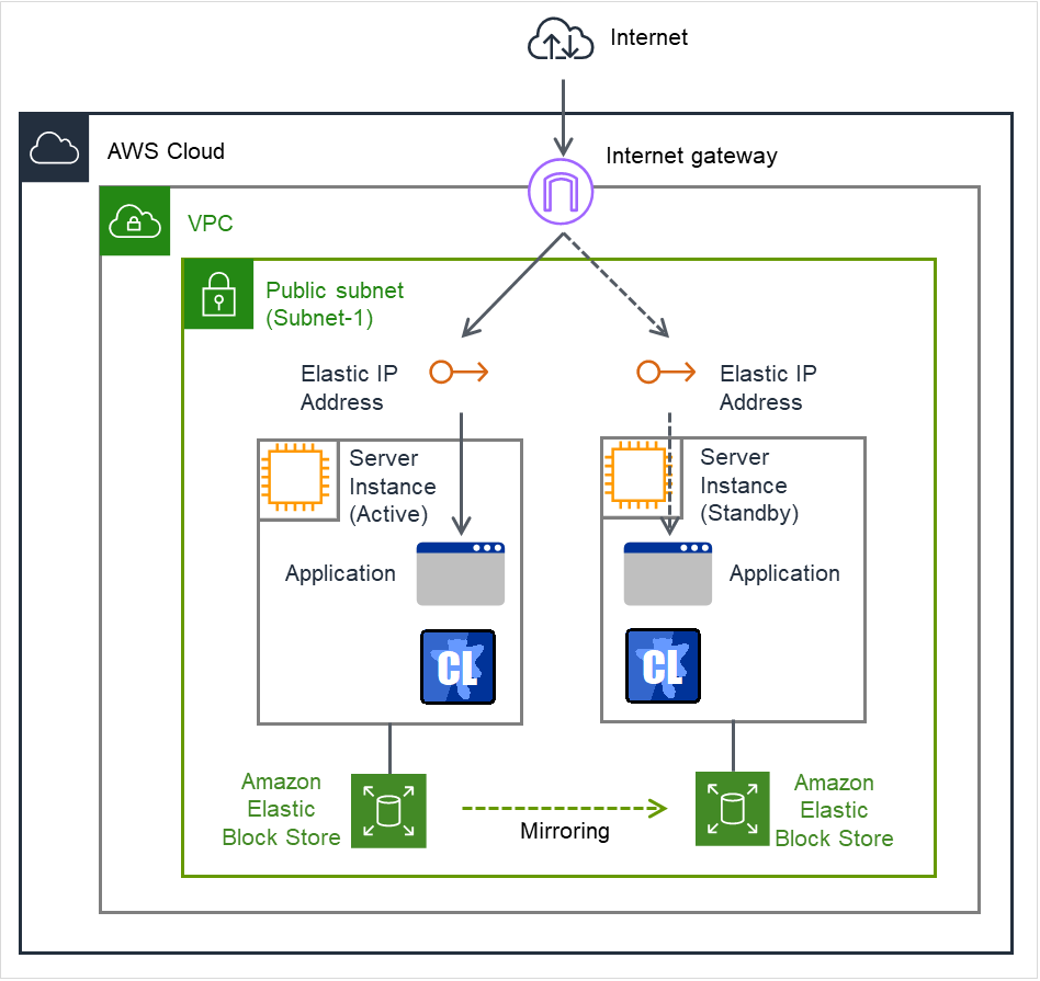
Fig. 3.129 Configuration with an AWS Elastic IP resource
3.14.3. Notes on AWS Elastic IP resources
See "Setting up AWS Elastic IP resources" in "Notes when creating EXPRESSCLUSTER configuration data" in "Notes and Restrictions" in the "Getting Started Guide".
For information on the settings of IAM, see "Getting Started Guide" -> "Notes and Restrictions" -> "Before installing EXPRESSCLUSTER" -> "IAM settings in the AWS environment".
3.14.4. Applying command line options to AWS CLI run from AWS Elastic IP resource
3.14.5. Applying environment variables to AWS CLI run from the AWS Elastic IP resource
3.14.6. Details tab
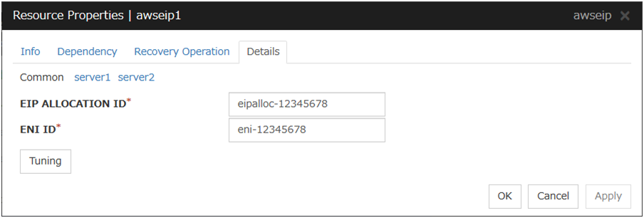
EIP ALLOCATION ID (Within 45 bytes)
For EIP control, specify the ID of the EIP to replace.
ENI ID (Within 45 bytes) Server Individual Setup
For EIP control, specify the ENI ID to which to allocate an EIP. In the Common tab, describes the ENI ID of any server, other servers, please to perform the individual setting.
AWS Elastic IP Resource Tuning Properties
Parameter tab
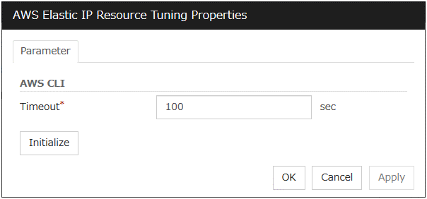
Timeout (1 to 999)
Set the timeout of the AWS CLI command to be executed for AWS Elastic IP resource activation/deactivation.
3.15. Understanding AWS Virtual IP resources
3.15.1. Dependencies of AWS Virtual IP resources
By default, this function does not depend on any group resource type.
3.15.2. What is an AWS Virtual IP resource?
Client applications can use AWS Virtual IP addresses(referred to as the VIP) to access the VPC in AWS environment.
By using VIP, clients do not need to be aware of switching access destination server when a failover occurs or moving a group migration.
AWS CLI command is executed for AWS Virtual IP resource when it is activated to update the route table information.
HA cluster with VIP control
This is used to place instances on private subnets (release business operations inside the VPC).
A configuration such as the following is assumed: Instances to be clustered, as well as the instance group accessing the instances, are placed on private subnets in each Availability Zone (referred to as AZ), and each instance can access the Internet via the NAT gateway placed on the public subnet.
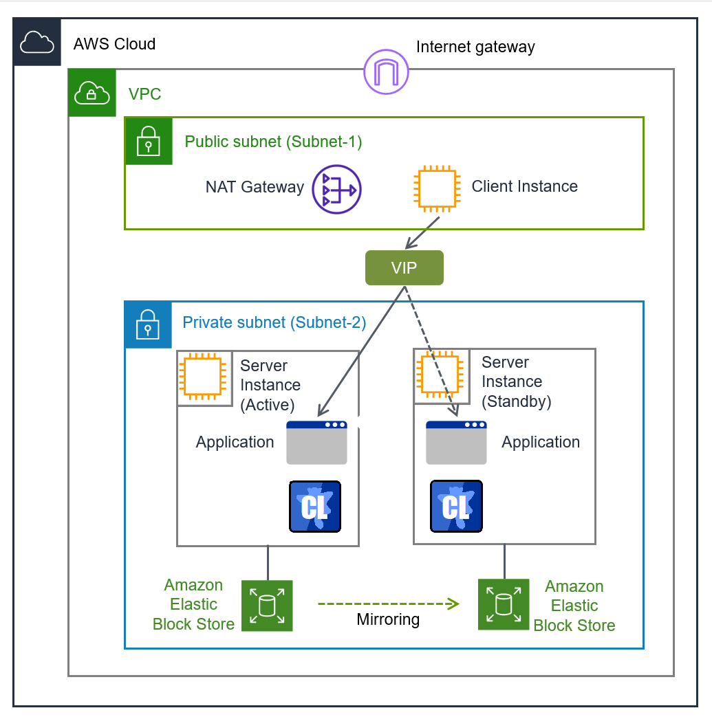
Fig. 3.130 Configuration with an AWS Virtual IP resource
3.15.3. Notes on AWS Virtual IP resources
See "Setting up AWS Virtual IP resources" in "Notes when creating EXPRESSCLUSTER configuration data" in "Notes and Restrictions" in the "Getting Started Guide".
For information on the settings of IAM, see "Getting Started Guide" -> "Notes and Restrictions" -> "Before installing EXPRESSCLUSTER" -> "IAM settings in the AWS environment".
3.15.4. Applying command line options to AWS CLI run from AWS Virtual IP resource
3.15.5. Applying environment variables to AWS CLI run from the AWS Virtual IP resource
3.15.6. Details tab
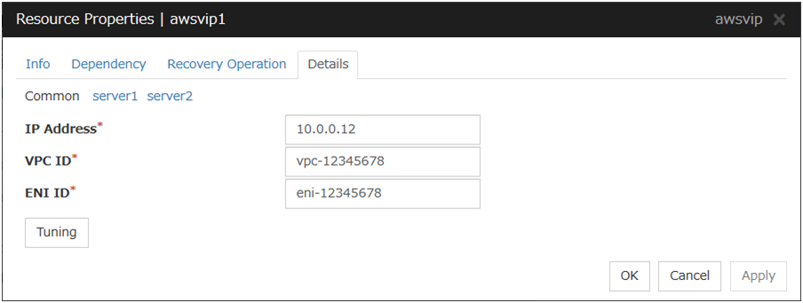
IP Address (Within 45 bytes)
For VIP control, specify the VIP address to use. As the VIP address, an IP address not belonging to a CIDR in the VPC must be specified.
VPC ID (Within 45 bytes) Server Individual Setup
For VIP control, specify the VPC ID to which the server belongs. To specify an individual VPC ID for the servers, enter the VPC ID of any server on the Common tab and specify a VPC ID for the other servers individually.For how to configure the routing, see the following:" Configuring the VPC Environment" in the "EXPRESSCLUSTER X HA Cluster Configuration Guide for Amazon Web Services (Linux)"
ENI ID (Within 45 bytes) Server Individual Setup
For VIP control, specify the ENI ID of VIP routing destination. For the ENI ID to specify, Source/Dest. Check must be disabled beforehand. This must be set for each server. On the Common tab, enter the ENI ID of any server, and specify an ENI ID for the other servers individually.
AWS Virtual IP Resource Tuning Properties
Parameter tab
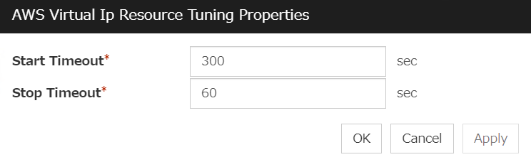
Start Timeout (1 to 9999)
Specify the timeout of the script to be used in activating AWS Virtual IP resources.
Stop Timeout (1 to 9999)
Specify the timeout of the script to be used in deactivating AWS Virtual IP resources.
3.16. Understanding AWS Secondary IP resources
3.16.1. Dependencies of AWS Secondary IP resources
By default, this function does not depend on any group resource type.
3.16.2. What is an AWS secondary IP resource?
Client applications can use Secondary IP addresses to access the VPC in AWS environment.
By using Secondary IP addresses, clients do not need to be aware of switching access destination server when a failover occurs or moving a group migration.
AWS Secondary IP resources allocate secondary IP addresses during activation, and deallocate them during deactivation.
HA cluster with Secondary IP control
This is used to place instances on private subnets (release business operations inside the VPC).
A configuration such as the following is assumed: Instances to be clustered, as well as the instance group accessing the instances, are placed on private subnets in each Availability Zone (referred to as AZ), and each instance can access the Internet via the NAT gateway placed on the public subnet.
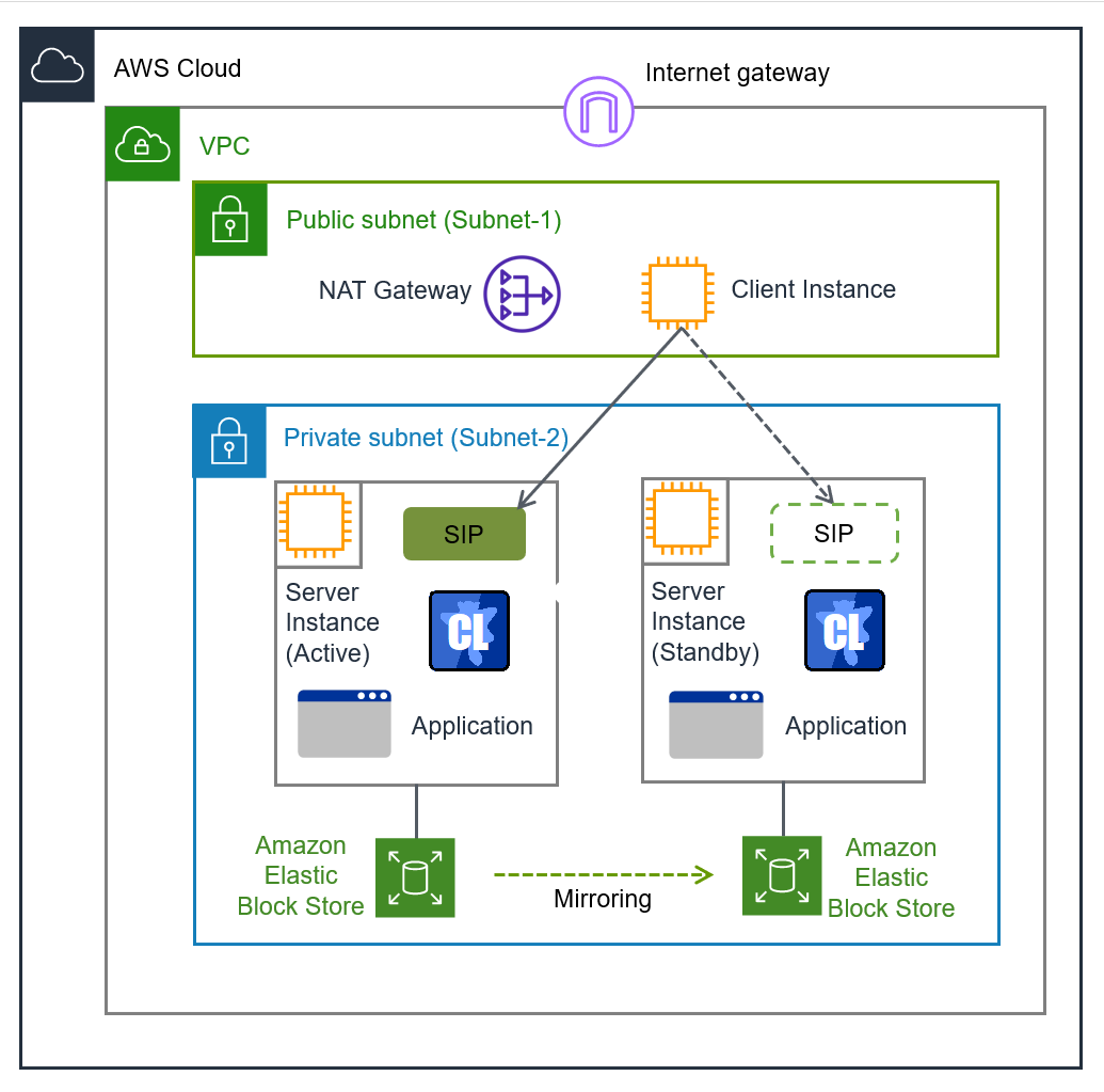
Fig. 3.131 Configuration with an AWS Secondary IP resource
Note
The term "SIP" in the above figure means a secondary IP address.
3.16.3. Notes on AWS secondary IP resources
See "Setting up AWS Secondary IP resources" in "Notes when creating EXPRESSCLUSTER configuration data" in "Notes and Restrictions" in the "Getting Started Guide".
For information on the settings of IAM, see "Getting Started Guide" -> "Notes and Restrictions" -> "Before installing EXPRESSCLUSTER" -> "IAM settings in the AWS environment".
3.16.4. Applying command line options to AWS CLI run from AWS Secondary IP resource
3.16.5. Applying environment variables to AWS CLI run from the AWS Secondary IP resource
3.16.6. Details tab
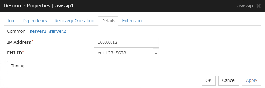
IP Address (Within 45 bytes)
Specify a secondary IP address existing within the subnet to which the instance belongs.
ENI ID (Within 45 bytes) Server Individual Setup
Specify the ENI ID of a network interface where the secondary IP address is allocated. This setting is required for each server: In the Common tab, enter the ENI ID of any server; in each of the other server tabs, specify the ENI ID of the corresponding server.
AWS Secondary IP Resource Tuning Properties
Parameter tab
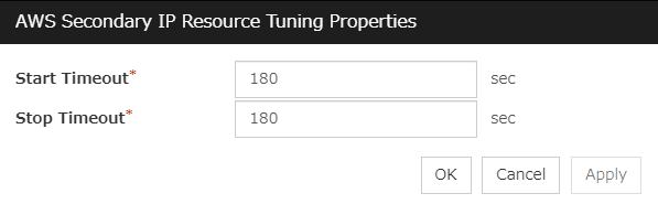
Start Timeout (1 to 9999)
Specify the timeout of the script to be used in activating AWS Secondary IP resources.
Stop Timeout (1 to 9999)
Specify the timeout of the script to be used in deactivating AWS Secondary IP resources.
3.17. Understanding AWS DNS resources
3.17.1. Dependencies of AWS DNS resources
By default, this function does not depend on any group resource type.
3.17.2. What is an AWS DNS resource?
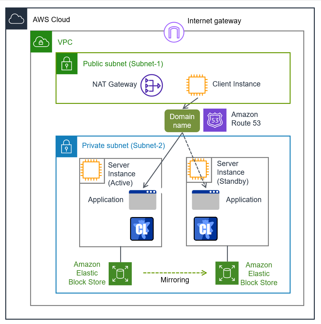
Fig. 3.132 Configuration with an AWS DNS resource
An AWS DNS resource registers an IP address corresponding to the virtual host name (DNS name) used in Amazon Web Services (hereinafter, referred to as "AWS") by executing AWS CLI at activation, and deletes it by executing AWS CLI at deactivation.
A client can access the node on which failover groups are active with the virtual host name.
By using AWS DNS resources, clients do not need to be aware of switching access destination node when a failover occurs or moving a group migration.
If using AWS DNS resources, you need to take the following preparations before establishing a cluster.
Creating Hosted Zone of Amazon Route 53
Installing AWS CLI
3.17.3. Activation timing of AWS DNS resources
AWS DNS resources are activated after waiting until an update to the DNS record is applied to Amazon Route 53.
Note
3.17.4. Notes on AWS DNS resources
In client access using a virtual host name (DNS name), if a failover group to which the AWS DNS resource is added resource is failed over, reconnection may be required.
See "Setting up AWS DNS resources" in "Notes when creating EXPRESSCLUSTER configuration data" in Notes and Restrictions" in the "Getting Started Guide".
For information on the settings of IAM, see "Getting Started Guide" -> "Notes and Restrictions" -> "Before installing EXPRESSCLUSTER" -> "IAM settings in the AWS environment".
3.17.5. Applying command line options to AWS CLI run from AWS DNS resource
3.17.6. Applying environment variables to AWS CLI run from the AWS DNS resource
3.17.7. Details tab
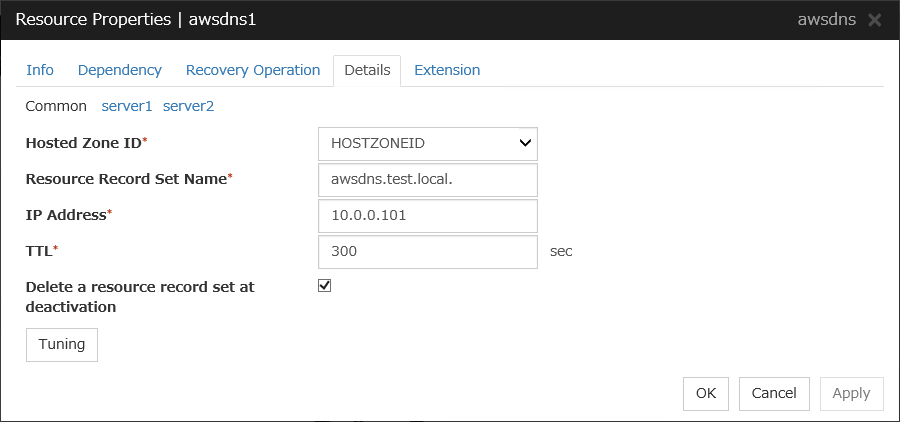
Hosted Zone ID (within 255 bytes)
Specify a Hosted Zone ID of Amazon Route 53.
Resource Record Set Name (within 255 bytes)
Specify the name of DNS A record. Put a dot (.) at the end of the name. When an escape character is included in Resource Record Set Name, a monitor error occurs. Set Resource Record Set Name with no escape character. Specify the value of Resource Record Set Name in lowercase letters.
IP Address (within 39 bytes) Server Individual Setup
Specify the IP address corresponding to the virtual host name (DNS name) (IPv4). For using the IP address of each server, enter the IP address on the tab of each server. For configuring a setting for each server, enter the IP address of an arbitrary server on Common tab, and configure the individual settings for the other servers.
TTL (0 to 2147483647)
Specify a time-to-live (TTL) for the DNS service cache.
Delete a record set at deactivation
Tuning
Opens the AWS DNS Resource Tuning Properties dialog box where you can make detailed settings for the AWS DNS resource.
AWS DNS Resource Tuning Properties
Parameter tab
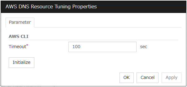
Timeout (1 to 999)
Make the setting of the timeout of AWS CLI command executed for the activation and/or deactivation of the AWS DNS resource.
3.18. Understanding Azure probe port resources
3.18.1. Dependencies of Azure probe port resources
By default, this function depends on the following group resource types:
Group resource type |
|---|
EXEC resource |
3.18.2. What is an Azure probe port resource?
Client applications can use the global IP address called a public virtual IP (VIP) address (referred to as a VIP in the remainder of this document) to access virtual machines on an availability set in the Microsoft Azure environment.
By using VIP, clients do not need to be aware of switching access destination server when a failover occurs or moving a group migration.
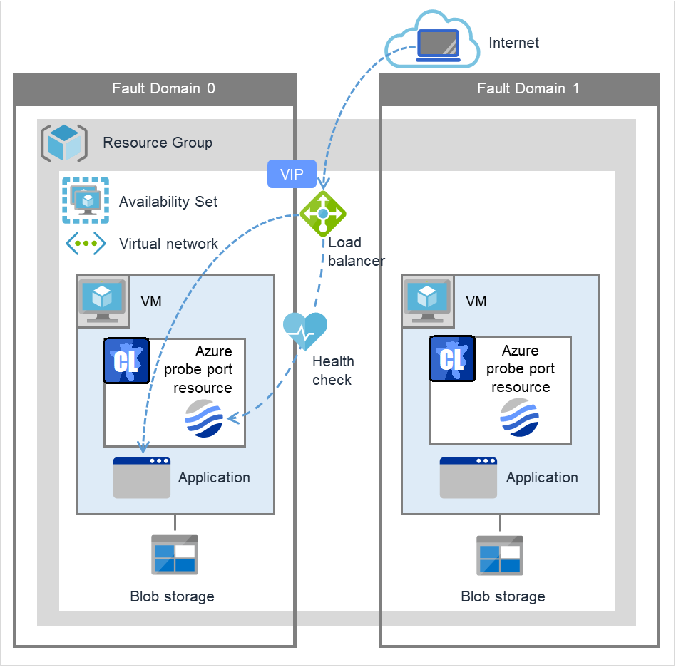
Fig. 3.133 Configuration with an Azure probe port resource
To access the cluster created on the Microsoft Azure environment in the figure above, specify the end point for communicating from the outside with VIP or the end point for communicating from the outside with the DNS name. The active and standby nodes of the cluster are switched by controlling the Microsoft Azure load balancer (Load Balancer in the figure above) from EXPRESSCLUSTER. For control, Health Check is used.
At activation, start the probe port control process for waiting for alive monitoring (access to the probe port) from the Azure load balancer.
At deactivation, stop the probe port control process for waiting for alive monitoring (access to the probe port).
Azure probe port resources also support the Internal Load Balancing of Microsoft Azure. For Internal Load Balancing, the VIP is the private IP address of Azure.
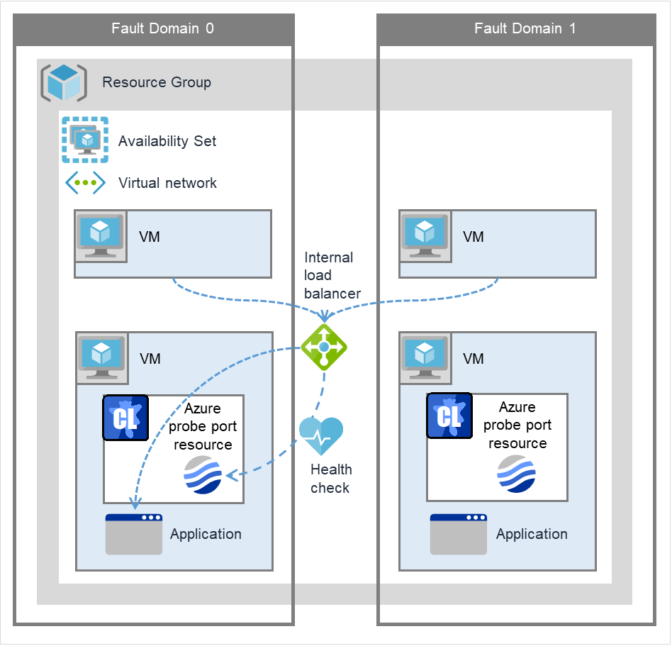
Fig. 3.134 Configuration with an Azure probe port resource (for Internal Load Balancing)
3.18.3. Notes on Azure probe port resources
If the private port and the probe port are the same, you need not add Azure probe port resources or Azure probe port monitor resources.
Refer to "Setting up Azure probe port resources" in "Notes when creating EXPRESSCLUSTER configuration data" in "Notes and Restrictions" in the "Getting Started Guide".
3.18.4. Details tab
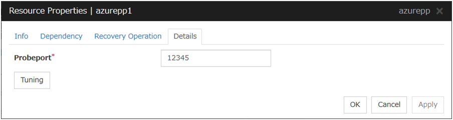
Probeport (1 to 65535)
Specify the port number used by the Azure load balancer for the alive monitoring of each server. Specify the value specified for Probe Port when creating an end point. For Probe Protocol, specify TCP.
Tuning
Display the Azure probe port Resource Tuning Properties dialog box. Specify detailed settings for the Azure probe port resources.
Azure Probe Port Resource Tuning Properties
Parameter tab
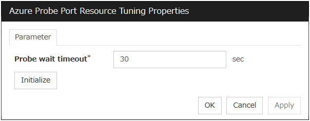
Probe wait timeout (5 to 999999999)
Specify the timeout time for waiting alive monitoring from the Azure load balancer. Check if alive monitoring is performed periodically from the Azure load balancer.
3.19. Understanding Azure DNS resources
3.19.1. Dependencies of Azure DNS resources
By default, this function does not depend on any group resource type.
3.19.2. What is an Azure DNS resource?
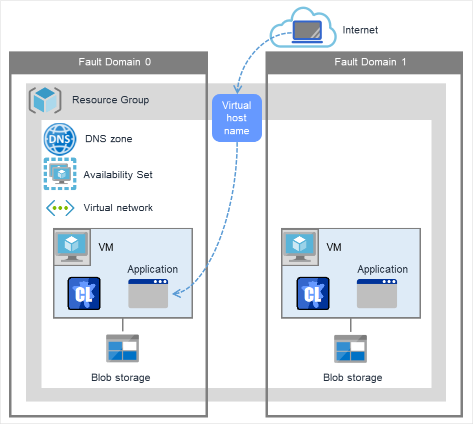
Fig. 3.135 Configuration with an Azure DNS resource
An Azure DNS resource controls an Azure DNS record set and DNS A record to obtain an IP address set from the virtual host name (DNS name).
A client can access the node on which failover groups are active with the virtual host name.
By using Azure DNS resources, clients do not need to be aware of switching access destination node on Azure DNS when a failover occurs or moving a group migration.
If using Azure DNS resources, you need to take the following preparations before establishing a cluster. For details, see "EXPRESSCLUSTER X HA Cluster Configuration Guide for Microsoft Azure (Linux)".
Creating Microsoft Azure Resource Group and DNS zone
Installing Azure CLI
Use Azure CLI (Azure CLI 2.0) for Red Hat Enterprise Linux 7 and OS with compatibility.
Installing Python (only when Azure CLI 2.0 is used)
3.19.3. Notes on Azure DNS resources
In client access using a virtual host name (DNS name), if a failover group to which the Azure DNS resource is added is failed over, reconnection may be required.
See "Setting up Azure DNS resources" in "Notes when creating EXPRESSCLUSTER configuration data" in "Notes and Restrictions" in the "Getting Started Guide".
See "Azure DNS resources" in " Before installing EXPRESSCLUSTER" in "Notes and Restrictions" in the "Getting Started Guide".
3.19.4. Details tab
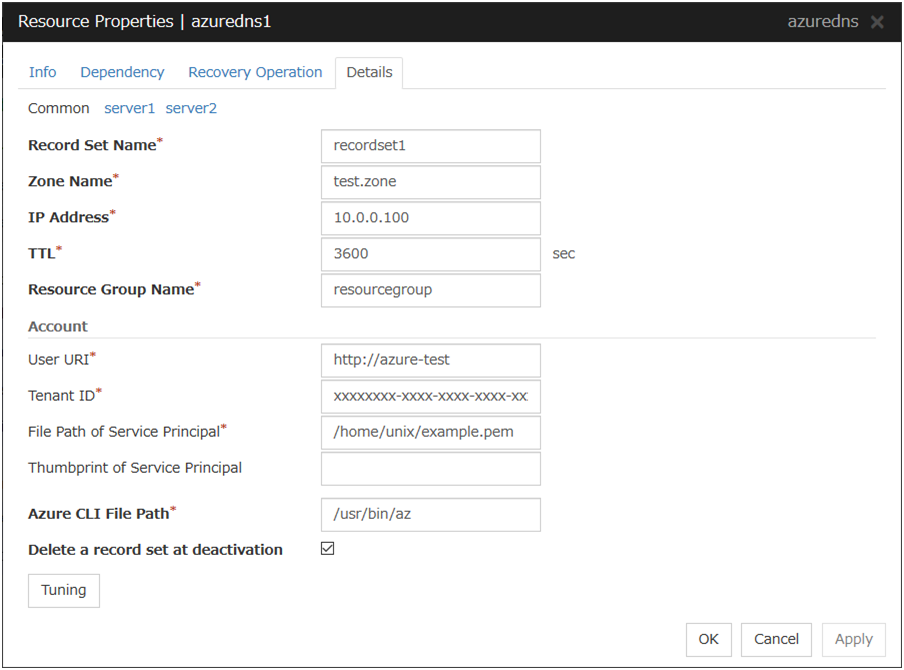
Record Set Name (within 253 bytes)
Specify the name of the record set in which Azure DNS A record is registered.
Zone Name (within 253 bytes)
Specify the name of the DNS zone to which the record set of Azure DNS belongs.
IP Address (within 39 bytes) Server Individual Setup
Specify the IP address corresponding to the virtual host name (DNS name) (IPv4). For using the IP address of each server, enter the IP address on the tab of each server. For configuring a setting for each server, enter the IP address of an arbitrary server on Common tab, and configure the individual settings for the other servers.
TTL (0 to 2147483647)
Specify a time-to-live (TTL) for the DNS service cache.
Resource Group Name (within 180 bytes)
Specify the name of Microsoft Azure Resource Group to which the DNS zone belongs.
User URI (within 2083 bytes)
Specify the user URI to log on to Microsoft Azure.
Tenant ID (within 36 bytes)
Specify the tenant ID to log on to Microsoft Azure.
File Path of Service Principal (within 1023 bytes)
Specify the full path to the file of a service principal (certificate) to log in to Microsoft Azure.
Thumbprint of Service Principal (within 256 bytes)
Specify the service principal to log in to Microsoft Azure (Thumbprint on Certificate). Enter only when using Azure CLI 1.0.
Azure CLI File Path (within 1023 bytes)
Specify the installation path of Azure CLI and the file name. Specify with an absolute path.
Delete a record set at deactivation
Tuning
Opens the AWS DNS Resource Tuning Properties dialog box where you can make detailed settings for the Azure DNS resource.
Server separate setting
Opens the Server Separate Setting dialog box. An IP address different depending on servers is set.
Azure DNS Resource Tuning Properties
Parameter tab
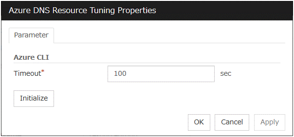
Timeout (1 to 999)
Make the setting of the timeout of the Azure CLI command executed for the activation and/or deactivation of the Azure DNS resource.
3.20. Understanding Google Cloud Virtual IP resources
3.20.1. Dependencies of Google Cloud Virtual IP resources
By default, this function depends on the following group resource types:
Group resource type |
|---|
EXEC resource |
3.20.2. What is an Google Cloud Virtual IP resource?
For virtual machines in the Google Cloud environment, client applications can use a virtual IP (VIP) address to connect to the node that constitutes a cluster. Using the VIP address eliminates the need for clients to be aware of switching between the virtual machines even after a failover or a group migration occurs.
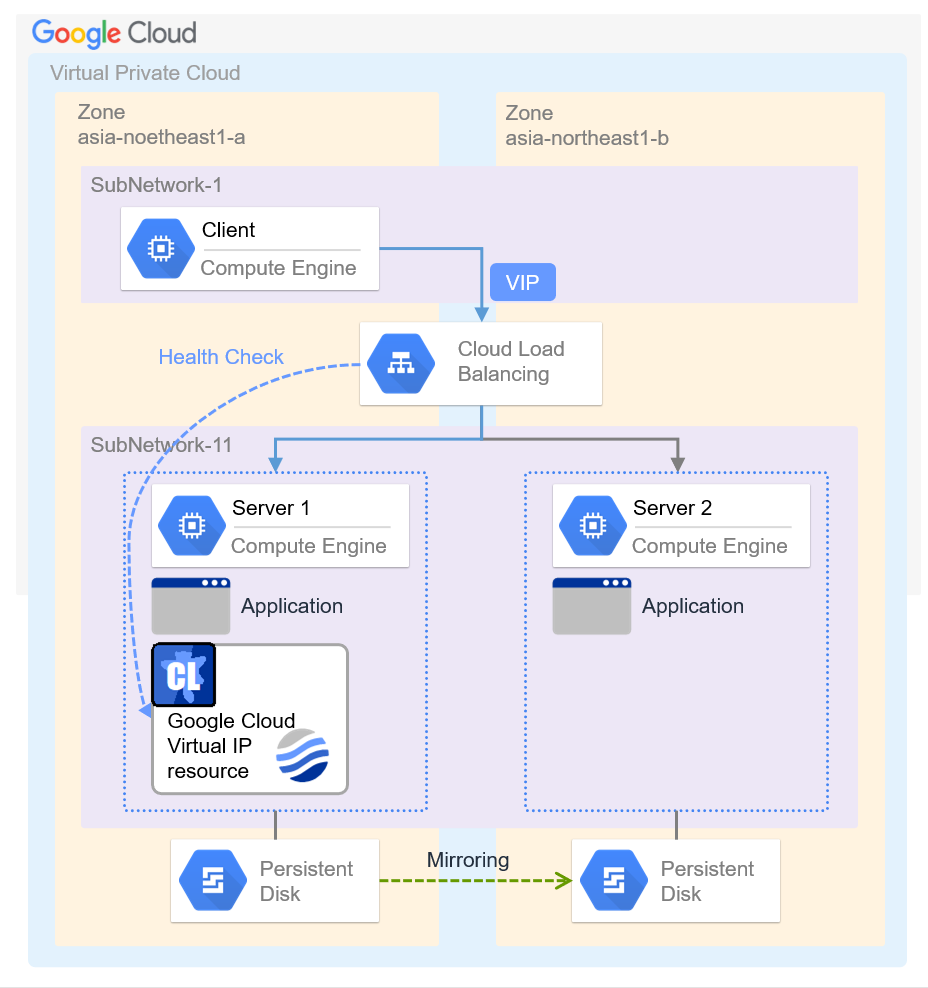
Fig. 3.136 Configuration with a Google Cloud Virtual IP resource
To access the cluster created in the Google Cloud environment as in the figure above, specify the port for communicating from the outside as well as the VIP address or DNS name. The active and standby nodes of the cluster are switched by controlling the load balancer of Google Cloud (Cloud Load Balancing in the figure above) from EXPRESSCLUSTER. For this control, Health Check (in the figure above) is used.
At activation, start the control process for awaiting a health check from the load balancer of Google Cloud, and open the port specified in Port Number.
At deactivation, stop the control process for awaiting the health check, and close the port specified in Port Number.
Google Cloud virtual IP resources support the internal load balancing of Google Cloud.
3.20.3. Notes on Google Cloud Virtual IP resources
- According to the Google Cloud specification, External TCP Network Load Balancer requires legacy health checks using the HTTP protocol.Google Cloud Virtual IP resources only support health checks that use the TCP protocol and cannot respond to health checks from External TCP Network Load Balancer.Therefore, HA cluster using Google Cloud Virtual IP resources by External TCP Network Load Balancer cannot be used. Use an Internal TCP Load Balancer.Refer to the following.Health checks overview:
If the private port is the same as the health-check port, you need not add Google Cloud virtual IP resources or Google Cloud virtual IP monitor resources.
Refer to "Getting Started Guide" -> "Notes and Restrictions" -> "Notes when creating EXPRESSCLUSTER configuration data" -> "Setting up Google Cloud Virtual IP resources".
3.20.4. Details tab
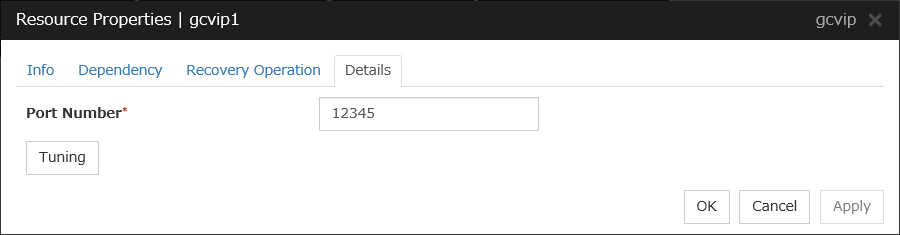
Port Number (1 to 65535)
Specify a port number to be used by the load balancer of Google Cloud for the health check of each node: the value specified as the port number in configuring the load balancer for health checks. For the load balancer, specify TCP load balancing.
Tuning
Displays the Google Cloud Virtual IP Resource Tuning Properties dialog box, where you can make advanced settings for the Google Cloud virtual IP resource.
Google Cloud Virtual IP Resource Tuning Properties
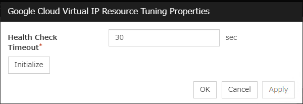
Health Check Timeout (5 to 999999999)
Specify a timeout value for awaiting a health check from the load balancer of Google Cloud, in order to check whether the load balancer periodically performs health checks.
3.21. Understanding Google Cloud DNS resources
3.21.1. Dependencies of Google Cloud DNS resources
By default, this function does not depend on any group resource type.
3.21.2. What is an Google Cloud DNS resource?
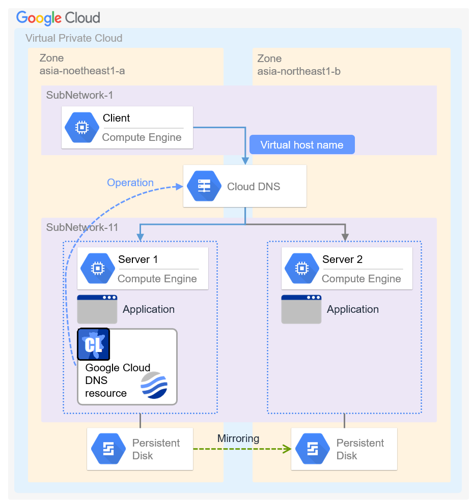
A Google Cloud DNS resource controls a Google Cloud DNS record set and DNS A record to obtain an IP address set from the virtual host name (DNS name).
A client can access the node on which failover groups are active with the virtual host name.
By using Google Cloud DNS resources, clients do not need to be aware of switching access destination node on Google Cloud DNS when a failover occurs or moving a group migration.
3.21.3. Notes on Google Cloud DNS resources
See "Setting up Google Cloud DNS resources" in "Notes when creating EXPRESSCLUSTER configuration data" in "Notes and Restrictions" in the "Getting Started Guide".
See "Google Cloud DNS resources" in " Before installing EXPRESSCLUSTER" in "Notes and Restrictions" in the "Getting Started Guide".
3.21.4. Details tab
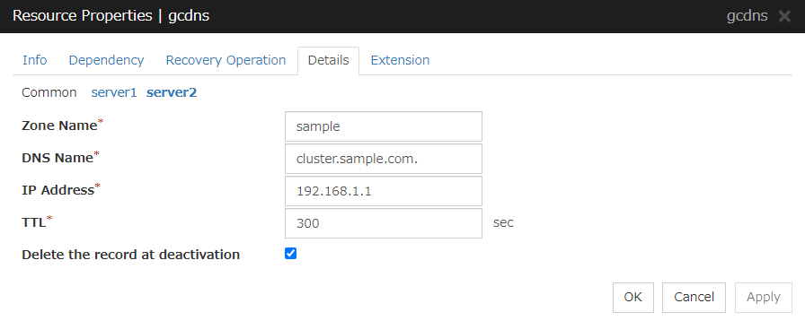
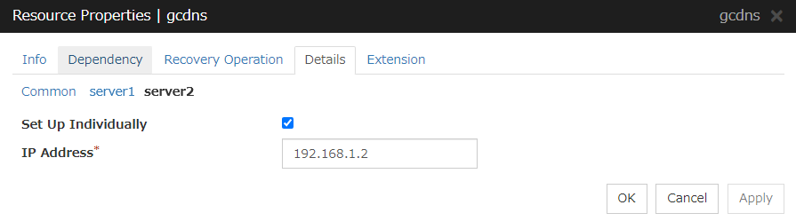
Zone Name (within 63 bytes)
Specify the name of the DNS zone to which the record set of Google Cloud DNS belongs.
DNS Name (within 253 bytes)
Specify the A record DNS name to be registered in Google Cloud DNS.
IP Address (within 39 bytes) Server Individual Setup
Specify the IP address corresponding to the virtual host name (DNS name) (IPv4). For using the IP address of each server, enter the IP address on the tab of each server. For configuring a setting for each server, enter the IP address of an arbitrary server on Common tab, and configure the individual settings for the other servers.
TTL (0 to 2147483647)
Specify a time-to-live (TTL) for the DNS service cache.
Delete a record set at deactivation
3.22. Understanding Oracle Cloud Virtual IP resources
3.22.1. Dependencies of Oracle Cloud Virtual IP resources
By default, this function depends on the following group resource types:
Group resource type |
|---|
EXEC resource |
3.22.2. What is an Oracle Cloud Virtual IP resource?
For virtual machines in the Oracle Cloud Infrastructure environment, client applications can use a public virtual IP (VIP) address to connect to the node that constitutes a cluster. Using the VIP address eliminates the need for clients to be aware of switching between the virtual machines even after a failover or a group migration occurs.
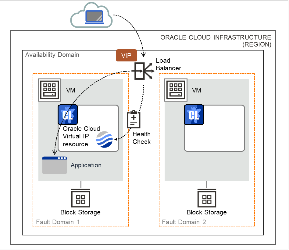
Fig. 3.138 Configuration with an Oracle Cloud Virtual IP resource
To access the cluster created in the Oracle Cloud Infrastructure environment as in the figure above, specify the port for communicating from the outside as well as the VIP (global IP) address or DNS name. The active and standby nodes of the cluster are switched by controlling the load balancer of Oracle Cloud Infrastructure (Load Balancer in the figure above) from EXPRESSCLUSTER. For this control, Health Check (in the figure above) is used.
At activation, start the control process for awaiting a health check from the load balancer of Oracle Cloud Infrastructure, and open the port specified in Port Number.
At deactivation, stop the control process for awaiting the health check, and close the port specified in Port Number.
Oracle Cloud virtual IP resources also support private load balancers of Oracle Cloud Infrastructure. For a private load balancer, the VIP address is the private IP address of Oracle Cloud Infrastructure.
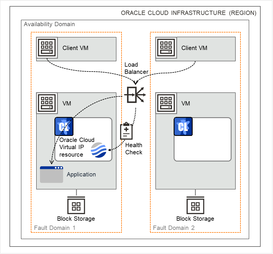
Fig. 3.139 Configuration with an Oracle Cloud Virtual IP resource (for a private load balancer)
3.22.3. Notes on Oracle Cloud Virtual IP resources
If the private port is the same as the health-check port, you need not add Oracle Cloud virtual IP resources or Oracle Cloud virtual IP monitor resources.
Refer to "Getting Started Guide" -> "Notes and Restrictions" -> "Notes when creating EXPRESSCLUSTER configuration data" -> "Setting up Oracle Cloud Virtual IP resources".
3.22.4. Details tab
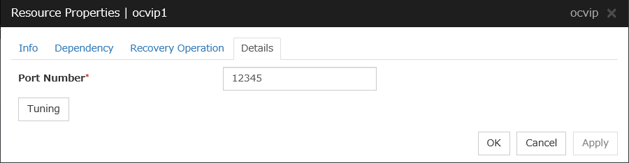
Port Number (1 to 65535)
Specify a port number to be used by the load balancer of Oracle Cloud Infrastructure for the health check of each node: the value specified as the port number in configuring the backend set for health checks. For the health check protocol, specify TCP.
Tuning
Displays the Oracle Cloud Virtual IP Resource Tuning Properties dialog box, where you can make advanced settings for the Oracle Cloud virtual IP resource.
Oracle Cloud Virtual IP Resource Tuning Properties
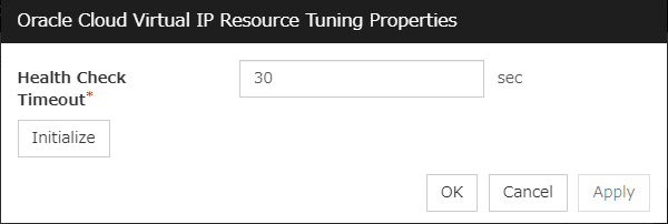
Health Check Timeout (5 to 999999999)
Specify a timeout value for awaiting a health check from the load balancer of Oracle Cloud Infrastructure, in order to check whether the load balancer periodically performs health checks.
3.23. Understanding Oracle Cloud DNS resources
3.23.1. Dependencies of Oracle Cloud DNS resources
By default, this function does not depend on any group resource type.
3.23.2. What is an Oracle Cloud DNS resource?
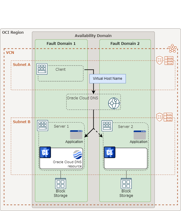
Fig. 3.140 Configuration with an Oracle Cloud DNS resource in a mono-region environment
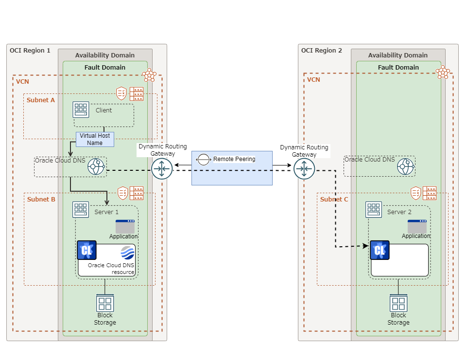
Fig. 3.141 Configuration with an Oracle Cloud DNS resource in a multi-region environment
A Oracle Cloud DNS resource controls a Oracle Cloud DNS record set and DNS A record to obtain an IP address set from the virtual host name (DNS name).
A client can access the node on which failover groups are active with the virtual host name.
By using Oracle Cloud DNS resources, clients do not need to be aware of switching access destination node on Oracle Cloud DNS when a failover occurs or moving a group migration.
3.23.3. Notes on Oracle Cloud DNS resources
See "Setting up Oracle Cloud DNS resources" in "Notes when creating EXPRESSCLUSTER configuration data" in "Notes and Restrictions" in the "Getting Started Guide".
See "CLI setting in the OCI environment" in "Notes when creating EXPRESSCLUSTER configuration data" in "Notes and Restrictions" in the "Getting Started Guide".
See "Policy setting in the OCI environment" in " Before installing EXPRESSCLUSTER" in "Notes and Restrictions" in the "Getting Started Guide".
3.23.4. Details tab
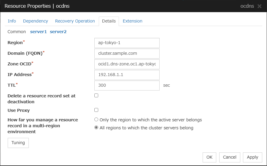
Region (within 48 bytes) Server Individual Setup
Enter the identifier of a region to which a server belong. For a multi-region environment, enter a region identifier in each server tab. If you set this item for each server: In the Common tab, enter the identifier of the region to which any of the servers belong; for other servers, set the identifiers separately.
Domain (FQDN) (within 254 bytes)
Enter a domain name (FQDN) to be registered in the Oracle Cloud DNS zone.
Note
For a multi-region environment, enter the same FQDN for all the regions.
Zone OCID (within 255 bytes) Server Individual Setup
Enter the OCID associated with the Oracle Cloud DNS zone name. For a multi-region environment, enter the OCID in each server tab. If you set for each server: In the Common tab, enter the zone OCID of one of the servers; for other servers, set it separately.
IP Address (within 39 bytes) Server Individual Setup
Specify the IP address corresponding to the virtual host name (DNS name) (IPv4). For using the IP address of each server, enter the IP address on the tab of each server. For configuring a setting for each server, enter the IP address of an arbitrary server on Common tab, and configure the individual settings for the other servers.
TTL (1 to 604800)
Specify a time-to-live (TTL) for the DNS service cache.
Delete a record set at deactivation
Use Proxy
How far you manage a resource record in a multi-region environment
Note
If you selected All regions to which the cluster servers belong
No activation failure is considered to have occurred even if a processing failure occurs to Oracle Cloud DNS in a region to which servers (without the failover group started) belong.
In the region, the A records of Oracle Cloud DNS are created or updated at intervals specified in Interval of Oracle Cloud DNS monitor resources.
Tuning
Opens the Oracle Cloud DNS Resource Tuning Properties dialog box where you can make detailed settings for the Oracle Cloud DNS resource.
Oracle Cloud DNS Resource Tuning Properties
Parameter tab
Detailed setting for parameter is displayed.
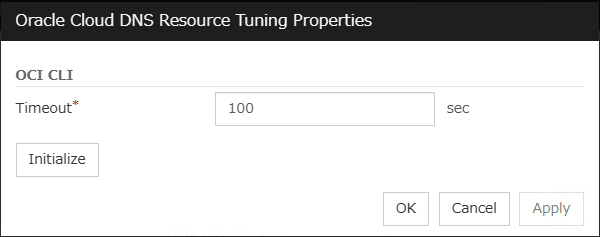
Timeout (1 to 999)
Make the setting of the timeout of the OCI CLI command executed for the activation and/or deactivation of the Oracle Cloud DNS resource.