1. Preface
1.1. Who Should Use This Guide
The Installation and Configuration Guide is intended for system engineers and administrators who want to build, operate, and maintain a cluster system. Instructions for designing, installing, and configuring a cluster system with EXPRESSCLUSTER are covered in this guide.
1.2. How This Guide is Organized
2. Determining a system configuration: Provides instructions for how to verify system requirements and determine the system configuration.
3. Configuring a cluster system: Helps you understand how to configure a cluster system.
4. Installing EXPRESSCLUSTER: Provides instructions for how to install EXPRESSCLUSTER.
5. Registering the license: Provides instructions for how to register the license.
6. Creating the cluster configuration data: Provides instructions for how to create the cluster configuration data with the Cluster WebUI.
7. Verifying a cluster system: Verify that the cluster system you have configured operates successfully.
8. Verifying operation: Run the dummy-failure test and adjust the parameters.
9. Preparing to operate a cluster system: Provides information on what you need to consider before starting to operate EXPRESSCLUSTER.
10. Uninstalling and reinstalling EXPRESSCLUSTER: Provides instructions for how to uninstall and reinstall EXPRESSCLUSTER.
1.3. EXPRESSCLUSTER X Documentation Set
The EXPRESSCLUSTER X manuals consist of the following six guides. The title and purpose of each guide is described below:
This guide is intended for all users. The guide covers topics such as product overview, system requirements, and known problems.
Installation and Configuration Guide
This guide is intended for system engineers and administrators who want to build, operate, and maintain a cluster system. Instructions for designing, installing, and configuring a cluster system with EXPRESSCLUSTER are covered in this guide.
This guide is intended for system administrators. The guide covers topics such as how to operate EXPRESSCLUSTER, function of each module and troubleshooting. The guide is supplement to the Installation and Configuration Guide.
This guide is intended for administrators and for system administrators who want to build, operate, and maintain EXPRESSCLUSTER-based cluster systems. The guide describes maintenance-related topics for EXPRESSCLUSTER.
This guide is intended for administrators and for system engineers who want to build EXPRESSCLUSTER-based cluster systems. The guide describes features to work with specific hardware, serving as a supplement to the Installation and Configuration Guide.
This guide is intended for administrators and for system engineers who want to build EXPRESSCLUSTER-based cluster systems. The guide describes EXPRESSCLUSTER X 4.0 WebManager, Builder, and EXPRESSCLUSTER Ver 8.0 compatible commands.
1.4. Conventions
In this guide, Note, Important, See also are used as follows:
Note
Used when the information given is important, but not related to the data loss and damage to the system and machine.
Important
Used when the information given is necessary to avoid the data loss and damage to the system and machine.
See also
Used to describe the location of the information given at the reference destination.
The following conventions are used in this guide.
Convention |
Usage |
Example |
|---|---|---|
Bold |
Indicates graphical objects, such as fields, list boxes, menu selections, buttons, labels, icons, etc. |
In User Name, type your name.
On the File menu, click Open Database.
|
Angled bracket within the command line |
Indicates that the value specified inside of the angled bracket can be omitted. |
|
Monospace |
Indicates path names, commands, system output (message, prompt, etc), directory, file names, functions and parameters. |
|
bold |
Indicates the value that a user actually enters from a command line. |
Enter the following:
clpcl -s -a
|
italic |
Indicates that users should replace italicized part with values that they are actually working with. |
|
 In the figures of this guide, this icon represents EXPRESSCLUSTER.
1.5. Contacting NEC
For the latest product information, visit our website below:
2. Determining a system configuration
This chapter provides instructions for determining the cluster system configuration that uses EXPRESSCLUSTER.
This chapter covers:
2.1. Steps from configuring a cluster system to installing EXPRESSCLUSTER
2.4. Checking system requirements for each EXPRESSCLUSTER module
2.1. Steps from configuring a cluster system to installing EXPRESSCLUSTER
Before you set up a cluster system that uses EXPRESSCLUSTER, you should carefully plan the cluster system with due consideration for factors such as hardware requirements, software to be used, and the way the system is used. When you have built the cluster, check to see if the cluster system is successfully set up before you start its operation.
This guide explains how to create a cluster system with EXPRESSCLUSTER through step-by-step instructions. Read each chapter by actually executing the procedures to install the cluster system. The following is the steps you take from designing the cluster system to operating EXPRESSCLUSTER:
See also
Refer to the "Reference Guide" as you need when operating EXPRESSCLUSTER by following the procedures introduced in this guide. See the "Getting Started Guide" for the latest information including system requirements and lease information.
Before installing EXPRESSCLUSTER, create the hardware configuration, the cluster system configuration and the information on the cluster system configuration.
2. Determining a system configuration
Review the overview of EXPRESSCLUSTER and determine the configurations of the hardware, network and software of the cluster system.
3. Configuring a cluster system
Plan a failover group that is to be the unit of a failover, and determine the information required to install the cluster system.Install EXPRESSCLUSTER and apply the license registration and the cluster configuration data to it.-
Install EXPRESSCLUSTER on the servers that constitute a cluster.
-
Register the license required to operate EXPRESSCLUSTER.
6. Creating the cluster configuration data
Based on the failover group information determined in the step 2, create the cluster configuration data by using the Cluster WebUI, and then configure a cluster.
-
Check if the cluster system has been created successfully.Conduct a dummy test, parameter tuning and operational simulation required to be done before operating the cluster system. The procedures to uninstall and reinstall are also explained in this section.
-
Check the operation and perform parameter tuning by a dummy-failure.
9. Preparing to operate a cluster system
Check the task simulation, backup and/or restoration and the procedure to handle an error, which are required to operate a cluster system.
10. Uninstalling and reinstalling EXPRESSCLUSTER
This chapter explains how to uninstall, and reinstall the EXPRESSCLUSTER.
2.2. What is EXPRESSCLUSTER?
EXPRESSCLUSTER is software that enhances availability and expandability of systems by a redundant (clustered) system configuration. The application services running on the active server are automatically inherited to the standby server when an error occurs on the active server.
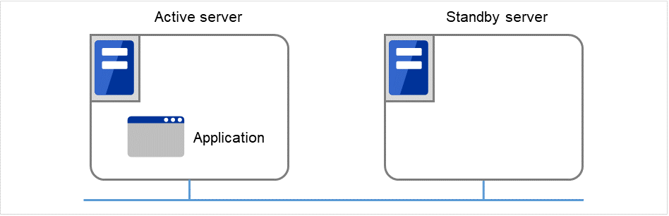
Fig. 2.1 Cluster system (in normal operation)
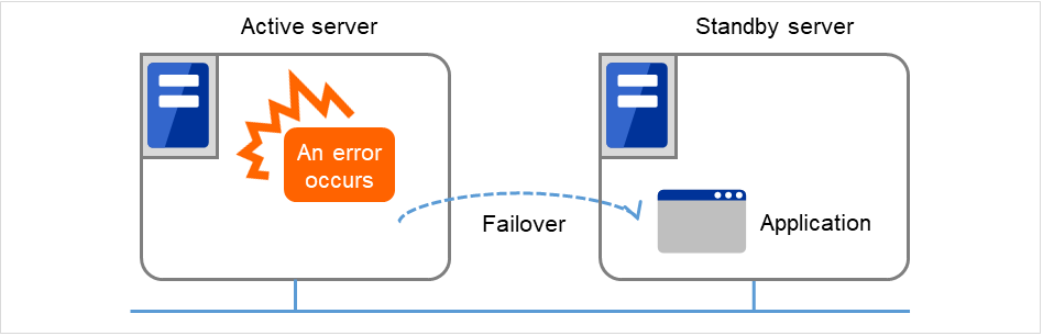
Fig. 2.2 Cluster system (when an error occurs)
The following can be achieved by installing a cluster system that uses EXPRESSCLUSTER.
- High availabilityThe down time is minimized by automatically failing over the applications and services to a "healthy" server when one of the servers which configure a cluster stops.
- High expandabilityBoth Windows and Linux support large scale cluster configurations having up to 32 servers.
See also
For details on EXPRESSCLUSTER, refer to "Using EXPRESSCLUSTER" in the "Getting Started Guide".
2.2.1. EXPRESSCLUSTER modules
EXPRESSCLUSTER X consists of following two modules:
- EXPRESSCLUSTER ServerThe main module of EXPRESSCLUSTER and has all high availability functions of the server. Install this module on each server constituting the cluster.
- Cluster WebUIThis is a tool to create the configuration data of EXPRESSCLUSTER and to manage EXPRESSCLUSTER operations. The Cluster WebUI is installed in EXPRESSCLUSTER Server, but it is distinguished from the EXPRESSCLUSTER Server because the Cluster WebUI is operated through a Web browser on the management PC.
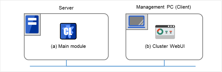
Fig. 2.3 Modules constituting EXPRESSCLUSTER
2.3. Planning system configuration
You need to determine an appropriate hardware configuration to install a cluster system that uses EXPRESSCLUSTER. The configuration examples of EXPRESSCLUSTER are shown below.
See also
For latest information on system requirements, refer to "Installation requirements for EXPRESSCLUSTER" and "Latest version information" in the "Getting Started Guide".
2.3.2. Example 1: Configuration using a shared disk with 2 nodes
This is the most commonly used system configuration:
Different models can be used for servers. However, mirroring disks should have the same drive letter in both servers.
Use cables for interconnection. A dedicated HUB can be used for connection the same way as 3-nodes configuration.
Connect COM (RS-232C) ports using a cross cable.
Client 1, which exists on the same LAN as that of the cluster servers, can access them through a floating IP address. Client 2, which exists on a remote LAN, can also access the cluster servers through a floating IP address. Using floating IP addresses does not require the router to be configured for them.
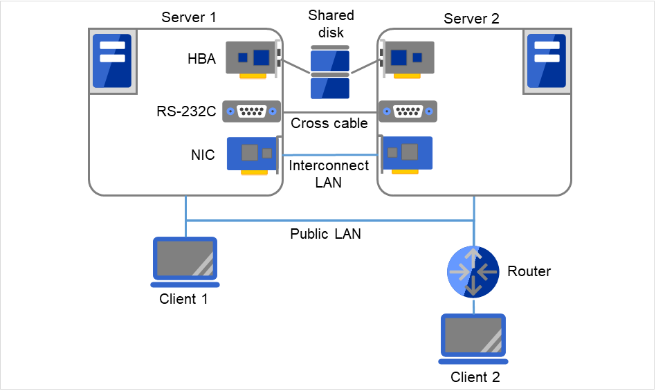
Fig. 2.4 Example of a configuration using a shared disk with two nodes
2.3.3. Example 2: Configuration using mirror disks with 2 nodes
Different models can be used for servers. However, the mirrors disk should have the same drive letter on both servers.
It is recommended to use cables for interconnection. (It is recommended to connect one server to another server directly using a cable. A HUB can also be used.)
On cluster servers (Servers 1 and 2), the same drive letter needs to be specified. For this configuration, different models can be used. However, their partitions for mirroring must be set at exactly the same size in bytes. This may be impossible if there is a difference in the disk geometry. For connecting the interconnect cable, direct connection between the servers is recommended, but connection via a hub is also fine. Client 1, which exists on the same LAN as that of the cluster servers, can access them through a floating IP address. Client 2, which exists on a remote LAN, can also access the cluster servers through a floating IP address. Using floating IP addresses does not require the router to be configured for them.
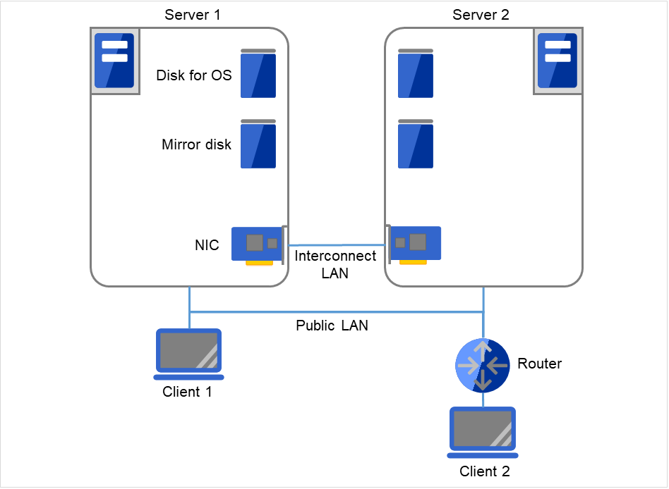
Fig. 2.5 Example of a configuration using mirror disks with two nodes
2.3.4. Example 3: Configuration using mirror partitions on the disks for OS with 2 nodes
A mirroring partition can be created on the disk used for the OS.
On Servers 1 and 2, the same drive letter needs to be specified. For this configuration, different models can be used. However, their partitions for mirroring must be set at exactly the same size in bytes. This may be impossible if there is a difference in the disk geometry. The partition for mirroring can be created on the same disk as that for the OS on each of the servers. Client 1, which exists on the same LAN as that of the cluster servers, can access them through a floating IP address. Client 2, which exists on a remote LAN, can also access the cluster servers through a floating IP address. Using floating IP addresses does not require the router to be configured for them.
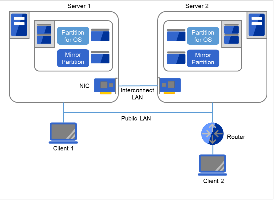
Fig. 2.6 Example of a configuration with two nodes, making the mirroring area coexist with the OS area
See also
For mirror partition settings, refer to "Group resource details" and "Understanding mirror disk resources" in the "Reference Guide".
2.3.5. Example 4: Configuring a remote cluster by using asynchronous mirror disks with 2 nodes
On Servers 1 and 2, the same drive letter needs to be specified. For this configuration, different models can be used. However, their partitions for mirroring must be set at exactly the same size in bytes. This may be impossible if there is a difference in the disk geometry. A client can access the cluster servers through a virtual IP (VIP) address. Using a VIP address requires a router to communicate the RIP host route.
Configuring a cluster between servers in remote sites by using WAN, as shown below, is a solution for disaster control.
Using asynchronous mirror disks can curb a decrease in disk performance due to the network delay. There is still a chance that the information updated immediately before a failover gets lost.
It is necessary to secure enough communication bandwidth for the traffic amount of updated information on mirror disks. Insufficient bandwidth can cause delay of communication with a business operation client or interruption of mirroring.
Use Dynamic DNS resource or Virtual IP resource to switch the connected server.
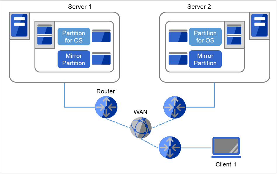
Fig. 2.7 Example of configuring a remote cluster by using asynchronous mirror disks with two nodes
See also
For information on resolving network partition and the VIP settings, see "Understanding virtual IP resources" in "Group resource details" and "Details on network partition resolution resources" in the "Reference Guide".
2.3.6. Example 5: Configuration using a shared disk with 3 nodes
The same way as 2 nodes-configuration, connect servers to a shared disk. The shared disk should have the same drive letter on all servers.
Interconnect LAN cables are connected to the interconnect hub, which is not connected to any other server or client.
It is not necessary to establish connectivity between servers using the connect COM (RS-232C).
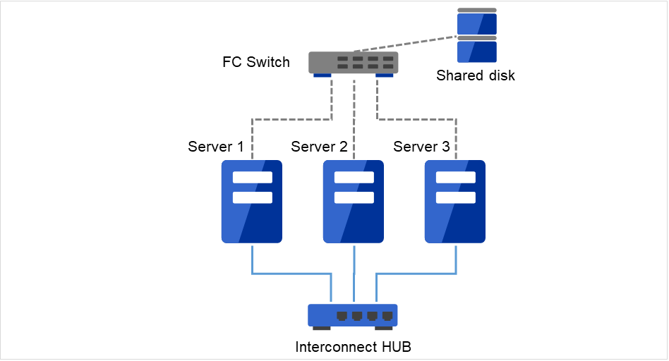
Fig. 2.8 Example of a configuration using a shared disk with three nodes
2.3.7. Example 6: Configuration using both mirror disks and a shared disk with 3 nodes
On Servers 1 and 2, the same drive letter needs to be specified. For this configuration, different models can be used. However, their partitions for mirroring must be set at exactly the same size in bytes. This may be impossible if there is a difference in the disk geometry.
It is possible to use both mirror disks and a shared disk on one cluster. In this example, the system is configured with three nodes: one for a shared disk type, one for a mirror disk type and, and one for standby.
It is not necessary to connect a shared disk to the server where business applications using the shared disk do not run. However the shared disk needs to have the same drive letter on the all connecting servers.
Install a dedicated HUB for interconnection.
It is not necessary to establish connectivity between servers using the connect COM (RS-232C).
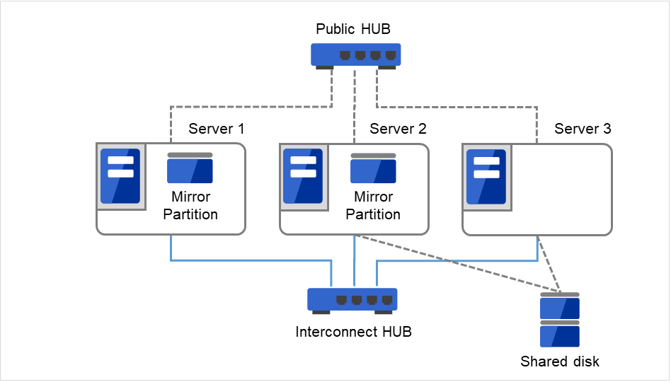
Fig. 2.9 Example of a configuration using both mirror disks and a shared disk with three nodes
2.3.8. Example 7: Configuration using the hybrid type with 3 nodes
This is a configuration with three nodes that consists of two nodes connected to the shared disk and one node having a disk to be mirrored.
The servers should not necessarily be the same model.
Install a dedicated HUB for interconnection and LAN of mirror disk connect.
Use a HUB with faster performance as much as possible.
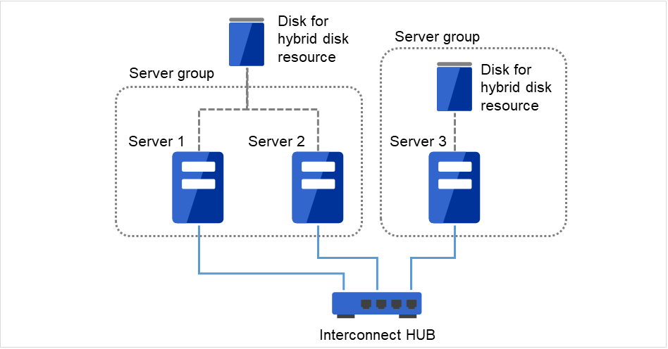
Fig. 2.10 Example of a configuration of the hybrid type with three nodes
Interconnect LAN cables are connected to the interconnect hub, which is not connected to any other server or client.
2.3.9. Example 8: Configuration using BMC-related functions with 2 nodes
This is an example of 2-node cluster configuration for using the forced stop function of a physical machine, chassis identify function, BMC heartbeat resources, and the BMC linkage functions of the external linkage monitor.
Different models of server can be used together, but each server must support the use of BMC linkage functions. For details about the available models, refer to "System requirements for hardware" of "Installation Requirements for EXPRESSCLUSTER" in the "Getting Started Guide".
When using BMC-related functions other than BMC heartbeat resources, connect the interconnect LAN and BMC management LAN via a dedicated HUB.
Use as fast a HUB as is available.

Fig. 2.11 Example of a configuration for using BMC-related functions with two nodes
Interconnect LAN and BMC LAN cables are connected to the hub, which is not connected to any other server or client.
2.4. Checking system requirements for each EXPRESSCLUSTER module
EXPRESSCLUSTER X consists of two modules: EXPRESSCLUSTER Server (main module) and Cluster WebUI. Check configuration and operation requirements of each machine where these modules will be used. For details about the operating environments, see "Installation requirements for EXPRESSCLUSTER" in the "Getting Started Guide".
2.5. Determining a hardware configuration
Determine a hardware configuration considering an application to be duplicated on a cluster system and how a cluster system is configured. Read "3. Configuring a cluster system" before you determine a hardware configuration.
See also
Refer to "3. Configuring a cluster system."
2.6. Settings after configuring hardware
After you have determined the hardware configuration and installed the hardware, verify the following:
2.6.2. Mirror partition settings (Required for mirror disks)
2.6.3. Adjustment of the operating system startup time (Required)
2.6.8. Setup of SNMP service (Required if ESMPRO Server is to be used cooperated with EXPRESSCLUSTER)
2.6.9. Setup of BMC and ipmiutil (Required for using the forced stop function of a physical machine and chassis ID lamp association)
2.6.10. Setup of a function equivalent to rsh provided by the network warning light vendor (Required)
2.6.2. Mirror partition settings (Required for mirror disks)
Set up partitions for mirror disk resources by following the steps below. This is required for a local disk (a disk connected to only one of the servers) to be mirrored with the shared disk in the hybrid configuration.
Note
When you cluster a single server and continue using data on the existing partitions, do not re-create the partitions. If you re-create partitions, data on the shared disks will be deleted.
Note
The partition to be allocated as described below cannot be used by mounting it on an NTFS folder.
- Allocate cluster partitions.Create partitions to be used by the mirror disk resources/hybrid disk resources. The partition is used for managing the status of mirror disk resources/hybrid disk resources. Create the partition in every server in the cluster that uses mirror resources. Create partitions by using "Disk Management" function of OS, and leave them as raw partition without formatting. Configure a drive letter for them.
Note
The cluster partition should be 1GB (1,073,741,824 bytes) or larger. Leave the disk cluster partition as RAW partition without formatting.
- Allocate data partitionsCreate the data partitions for mirroring by mirror disk resources/hybrid disk resources. For mirror disk resources, create the data partitions on the two servers on which disk mirroring is performed.Format partitions with NTFS from "Disk Management" function of OS and configure a drive letter.
Note
When partitions (drive) to be mirrored already exist (in the cases such as reinstalling EXPRESSCLUSTER), you do not need to create partitions again. When data that should be mirrored already exist on partitions, if you create partitions again or format partitions, the data will be deleted.A drive with a system drive and/or page file and a drive where EXPRESSCLUSTER is installed cannot be used as partitions for mirror disk resources. The data partitions in both servers must be precisely the same size in byte. If the geometries of the servers differ among the servers, it might not be able to create precisely same size of partitions. Check the partition sizes with the clpvolsz command and adjust them. The same drive letter must be configured on the partitions in the servers.
2.6.3. Adjustment of the operating system startup time (Required)
It is necessary to configure the time from power-on of each node in the cluster to the server operating system startup to be longer than the following:
The time from power-on of the shared disk to the point they become available.
Heartbeat timeout time (30 seconds by default.)
Adjustment of the startup time is necessary to prevent the following problems:
If the cluster system is started by powering on the shared disk and servers, starting a shared disk is not completed before the OS is rebooted. OS is started in the status where the shared disk is not recognized, and activation of disk resources fails.
A failover fails if a server, with data you want to fail over by rebooting the server, reboots within the heartbeat timeout. This is because a remote server assumes that the heartbeat is continued.
Consider the times durations above and adjust the operating system startup time by using the bcdedit command of Windows.
Note
2.6.4. Verification of the network settings (Required)
On all servers in the cluster, verify the status of the following network resources using the ipconfig or ping command.
Public LAN (used for communication with all the other machines)
LAN dedicated to interconnect (used for communication between EXPRESSCLUSTER Servers)
Host name
Note
It is not necessary to specify the IP addresses of floating IP resources virtual resources used in the cluster in the operating system.
2.6.5. Verification of the firewall settings (Required)
EXPRESSCLUSTER uses several port numbers for communication between the modules. For details about the port numbers to be used, see "Before installing EXPRESSCLUSTER" of "Notes and Restrictions" in the "Getting Started Guide".
2.6.6. Server clock synchronization (Recommended)
It is recommended to regularly synchronize the clocks of all the servers in the cluster. Make the settings that synchronize server clocks through protocol such as ntp on a daily basis.
Note
When the time of each server is not synchronized, the system time on the server from a client's point of view may change at a failover or group moving, which can lead to a failure of the operation of the application used in this system. The times of logs become different between servers, resulting in delay of failure analysis at occurrence of error.
Note
If the date or time setting on the OS is changed while a System monitor resource or a Process resource monitor resource is operating, the System monitor resource or the Process resource monitor resource may not operate normally.
2.6.7. Power saving function - OFF (Required)
In EXPRESSCLUSTER, power saving function (for example, standby or hibernation) with OnNow, ACPI, and/or APM functions cannot be used. Make sure to turn off the power saving function.
2.6.8. Setup of SNMP service (Required if ESMPRO Server is to be used cooperated with EXPRESSCLUSTER)
SNMP service is required if ESMPRO Server is to be used cooperated with EXPRESSCLUSTER. Set up SNMP service first before installing EXPRESSCLUSTER.
2.6.9. Setup of BMC and ipmiutil (Required for using the forced stop function of a physical machine and chassis ID lamp association)
For using the forced stop function of a physical machine and Chassis ID lamp association, configure the Baseboard Management Controller (BMC) of the servers to enable the communication between IP addresses of LAN ports for managing BMC and IP addresses used by the OS. These functions are not available when BMC is not installed on the server or when the network for managing BMC is disabled. For information on how to configure the BMC, refer to the manuals of your server.
Use ipmiutil of the versions 2.0.0 to 3.0.8
EXPRESSCLUSTER uses the hwreset command or ireset command, and alarms command or ialarms command of ipmiutil. To execute these commands without specifying path, include the path of the ipmiutil execution file in the system environment variable PATH or copy the execution file to the folder including the variable in its path (for example, the bin folder in the folder where EXPRESSCLUSTER is installed).
Because EXPRESSCLUSTER does not use the function that requires the IPMI driver, it is not necessary to install the IPMI driver.
To control BMC via LAN by the above commands, an IPMI account with Administrator privilege in BMC in each server. When you use NEC Express5800/100 series server, use User IDs 4 or later to add or change the account, because User IDs 3 or earlier are reserved by other tools. Use tools complying with the IPMI standards such as IPMITool for checking and changing account configuration.
2.6.10. Setup of a function equivalent to rsh provided by the network warning light vendor (Required)
For using the network warning light, set up a command equivalent to rsh supported by the warning light vendor.
3. Configuring a cluster system
This chapter provides information required to configure a cluster including requirements of applications to be duplicated, cluster topology, and explanation on resources constituting a cluster.
This chapter covers:
3.1. Configuring a cluster system
This chapter provides information necessary to configure a cluster system, including the following topics:
Determining a cluster system topology
Determining applications to be duplicated
Creating the cluster configuration data
The following is a typical example of cluster environment with 2 nodes where standby is uni-directional.

Fig. 3.1 Example of a 2-node and uni-directional standby cluster environment
FIP1 |
10.0.0.11
(to be accessed by Cluster WebUI clients)
|
FIP2 |
10.0.0.12
(to be accessed by operation clients)
|
NIC1-1 |
192.168.0.1 |
NIC1-2 |
10.0.0.1 |
NIC2-1 |
192.168.0.2 |
NIC2-2 |
10.0.0.2 |
Serial port |
COM1 |
Shared disk
Drive letter of the disk heartbeat
Q
File system
RAW
Drive letter of the switchable partition for resources
R
File system
NTFS
3.2. Determining a cluster topology
EXPRESSCLUSTER supports multiple cluster topologies. There are uni-directional standby cluster system that considers one server as an active server and other as standby server, and multi-directional standby cluster system in which both servers act as active and standby servers for different operations.
- Uni-directional standby cluster systemIn this operation, only one application runs on an entire cluster system. There is no performance deterioration even when a failover occurs. However, resources in a standby server will be wasted.
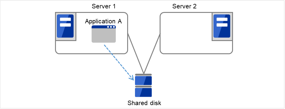
Fig. 3.2 Uni-directional standby cluster system
- Multi-directional standby cluster system with the same applicationIn this operation, the same application runs on more than one server simultaneously in a cluster system. Applications used in this system must support multi-directional standby operations.
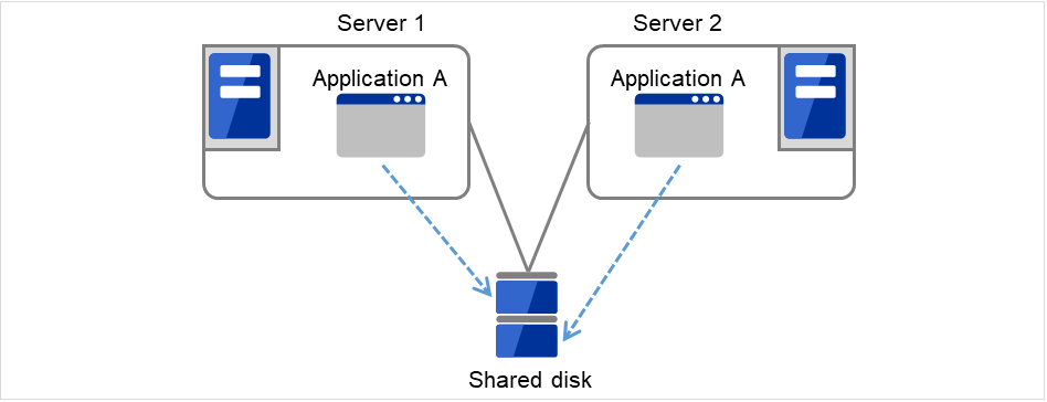
Fig. 3.3 Multi-directional standby cluster system with the same application
- Multi-directional standby cluster system with different applicationsIn this operation, different applications run on different servers and standby each other. Resources will not be wasted during normal operation; however, two applications run on one server after failing over and system performance deteriorates.
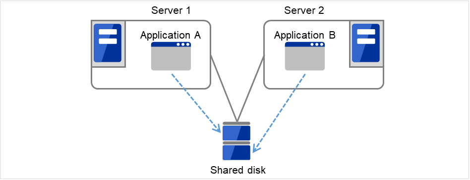
Fig. 3.4 Multi-directional standby cluster system with different applications
3.2.1. Failover in uni-directional standby cluster
On a uni-directional standby cluster system, the number of groups for an operation service is limited to one as described in the diagrams below:
3.2.1.1. When a shared disk is used
1. Server 1 runs Application A. Application A can be run on only one server in the same cluster.
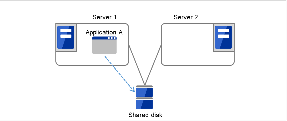
Fig. 3.5 Uni-directional standby cluster with a shared disk (1): in normal operation
Server 1 crashes due to some error.
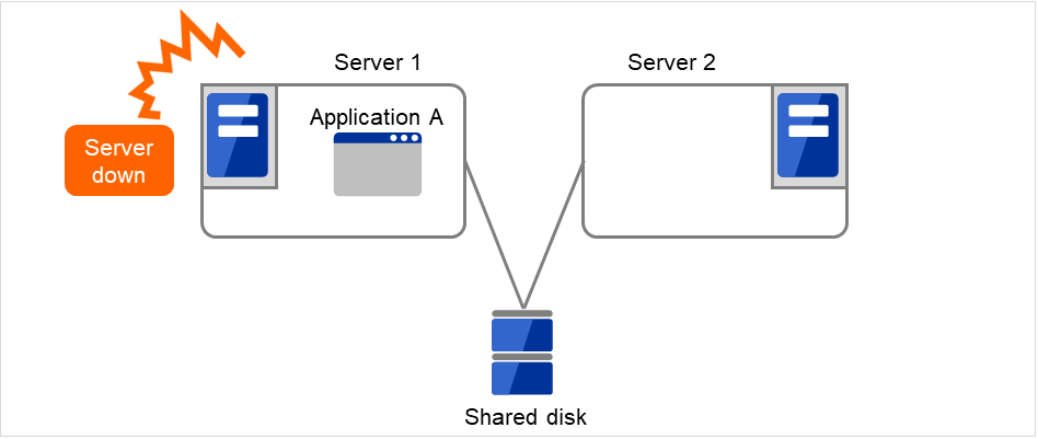
Fig. 3.6 Uni-directional standby cluster with a shared disk (2): when the server crashes
The application is failed over from Server 1 to Server 2.
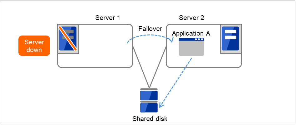
Fig. 3.7 Uni-directional standby cluster with a shared disk (3): during a failover
After Server 1 is restored, a group transfer can be made for Application A to be returned from Server 2 to Server 1.
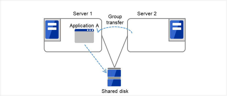
Fig. 3.8 Uni-directional standby cluster with a shared disk (4): after the server is restored
3.2.1.2. When mirror disks are used
1. Server 1 runs Application A. Application A can be run on only one server in the same cluster.
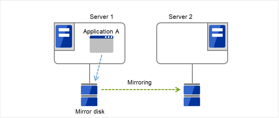
Fig. 3.9 Uni-directional standby cluster with mirror disks (1): in normal operation
Server 1 crashes due to some error.
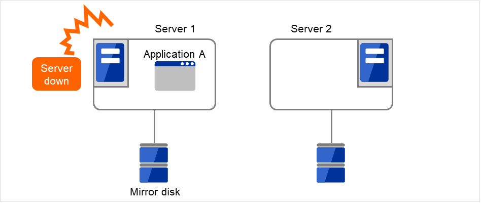
Fig. 3.10 Uni-directional standby cluster with mirror disks (2): when the server crashes
The application is failed over from Server 1 to Server 2.
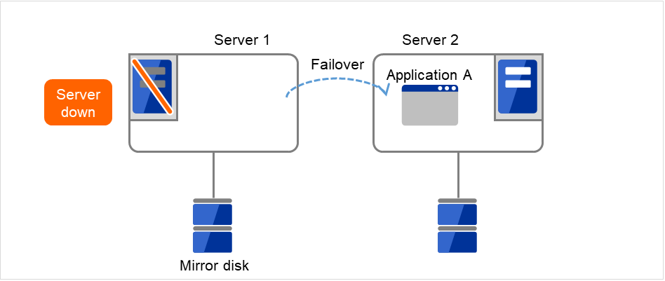
Fig. 3.11 Uni-directional standby cluster with mirror disks (3): during a failover
To resume the application, data is recovered from Server 2's mirror disk.
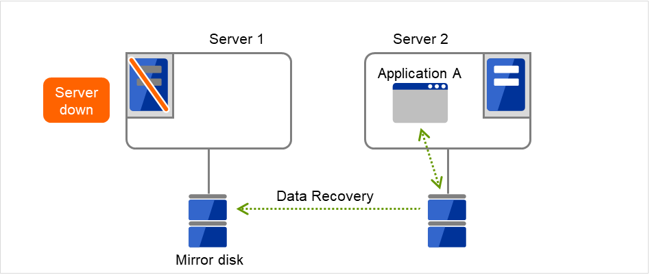
Fig. 3.12 Uni-directional standby cluster with mirror disks (4): during data recovery
After Server 1 is restored, a group transfer can be made for Application A to be returned from Server 2 to Server 1.
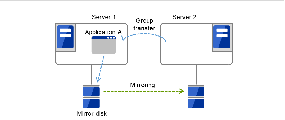
Fig. 3.13 Uni-directional standby cluster with mirror disks (5): After the server is restored
3.2.2. Failover in multi-directional standby cluster
On a multi-directional standby cluster system, different applications run on servers. If a failover occurs on the one sever, multiple applications start to run on the other server. As a result, the failover destination server is more loaded than the time of normal operation and performance decreases.
3.2.2.1. When a shared disk is used
Server 1 runs Application A while Server 2 runs Application B.
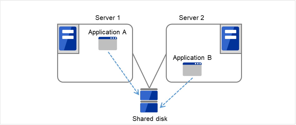
Fig. 3.14 Multi-directional standby cluster with a shared disk (1): in normal operation
Server 1 crashes due to some error.
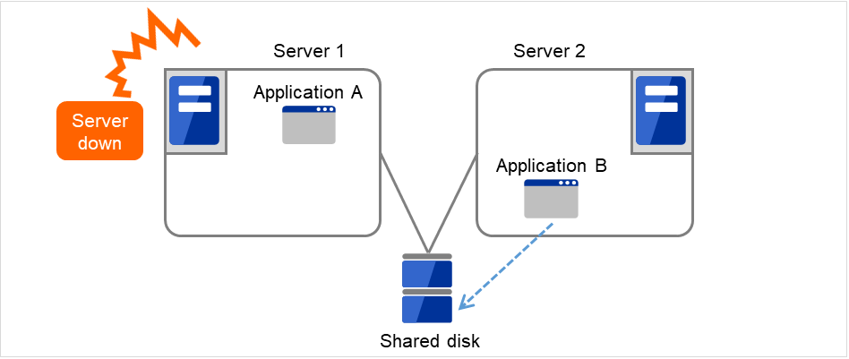
Fig. 3.15 Multi-directional standby cluster with a shared disk (2): when the server crashes
Application A is failed over from Server 1 to Server 2.
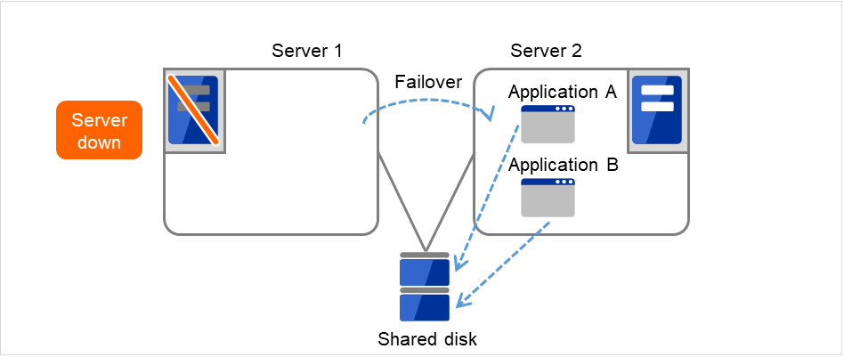
Fig. 3.16 Multi-directional standby cluster with a shared disk (3): during a failover
After Server 1 is restored, a group transfer can be made for Application A to be returned from Server 2 to Server 1.
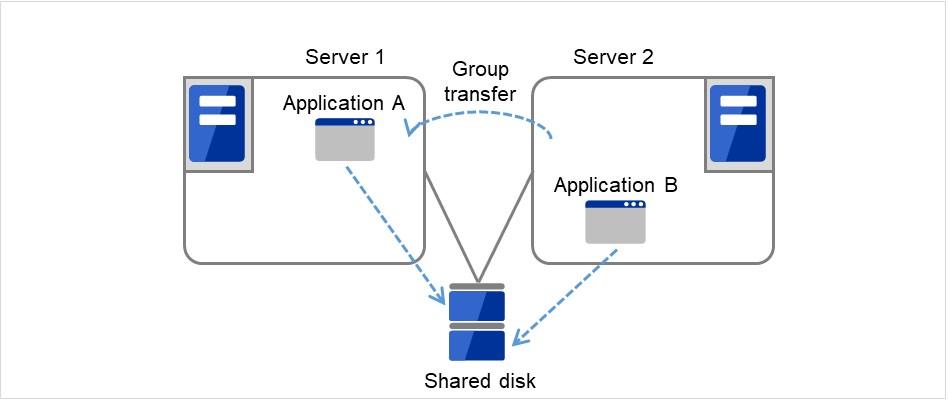
Fig. 3.17 Multi-directional standby cluster with a shared disk (4): after the server is restored
3.2.2.2. When mirror disks are used
Server 1 runs Application A while Server 2 runs Application B.
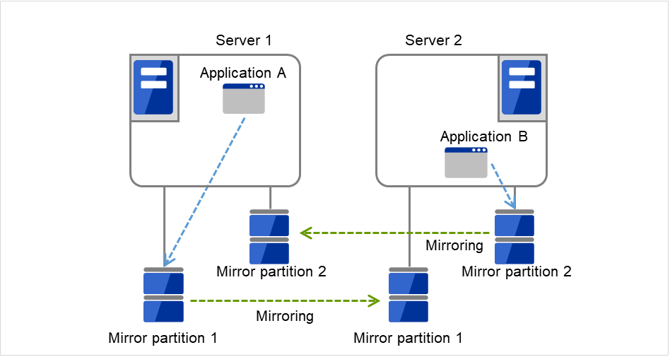
Fig. 3.18 Multi-directional standby cluster with mirror disks (1): in normal operation
Server 1 crashes due to some error.
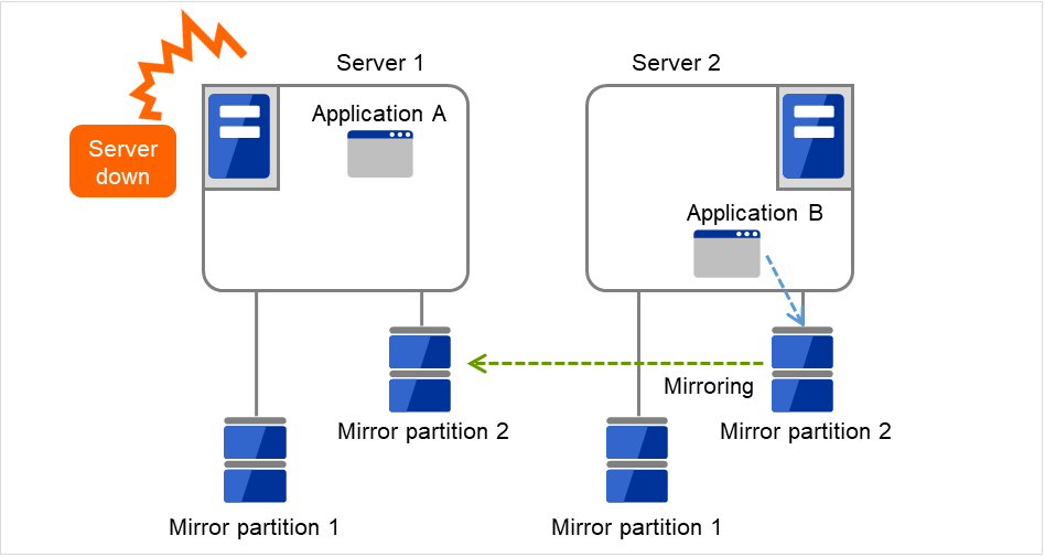
Fig. 3.19 Multi-directional standby cluster with mirror disks (2): when the server crashes
Application A is failed over from Server 1 to Server 2.
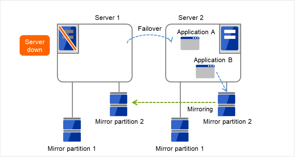
Fig. 3.20 Multi-directional standby cluster with mirror disks (3): during a failover
To resume Application A, data is recovered from Server 2's Mirror partition 1.
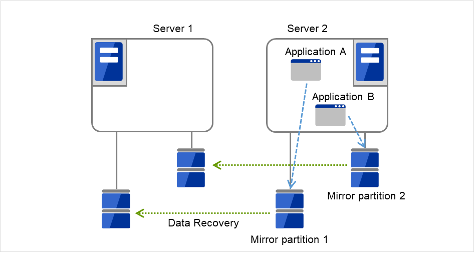
Fig. 3.21 Multi-directional standby cluster with mirror disks (4): during data recovery
After Server 1 is restored, a group transfer can be made for Application A to be returned from Server 2 to Server 1.
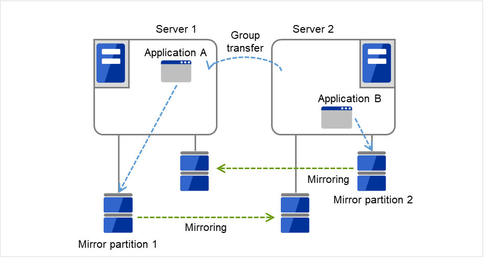
Fig. 3.22 Multi-directional standby cluster with mirror disks (5): after the server is restored
3.3. Determining applications to be duplicated
When you determine applications to be duplicated, study candidate applications taking what is described below into account to see whether or not they should be clustered in your EXPRESSCLUSTER cluster system.
3.3.1. Server applications
3.3.1.1. Note 1: Data recovery after an error
If an application was updating a file when an error has occurred, the file update may not be completed when the standby server accesses to that file after the failover.
The same problem can happen on a non-clustered server (single server) if it goes down and then is rebooted. In principle, applications should be ready to handle this kind of errors. A cluster system should allow recovery from this kind of errors without human interventions (from a script).
3.3.1.2. Note 2: Application termination
When EXPRESSCLUSTER stops or transfers (performs online failback of) a group for application, it unmounts the file system used by the application group. Therefore, you have to issue an exit command for applications so that all files on the shared disk or mirror disk are stopped.
Typically, you give an exit command to applications in their stop scripts; however, you have to pay attention if an exit command completes asynchronously with termination of the application.
3.3.1.3. Note 3: Location to store the data
EXPRESSCLUSTER can pass the following types of data between severs:
Data in the switchable partition on the disk resource, or data in the data partition on the mirror disk resource/hybrid disk resource.
Data type
Example
Where to store
Data to be shared among servers
User data, etc.
Switching partition of the disk resource or data partition of the mirror disk resource/hybrid disk resource
Data specific to a server
Programs, configuration data
On server's local disks
3.3.1.4. Note 4: Multiple application service groups
When you run the same application service in the multi-directional standby operation, you have to assume (in case of degeneration due to a failure) that multiple application groups are run by the same application on a server.Applications should have capabilities to take over the passed resources by one of the following methods described in the diagram below. A single server is responsible for running multiple application groups.The figures displayed below are the same with an example of a shared disk and/or mirror disk.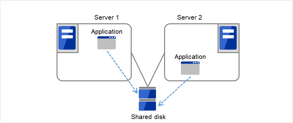
Fig. 3.23 Application running normally on each server in a multi-directional standby cluster
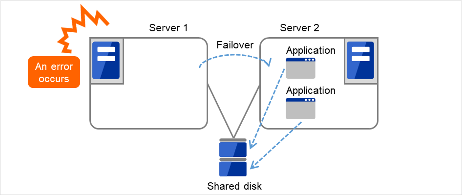
Fig. 3.24 Starting up multiple instances
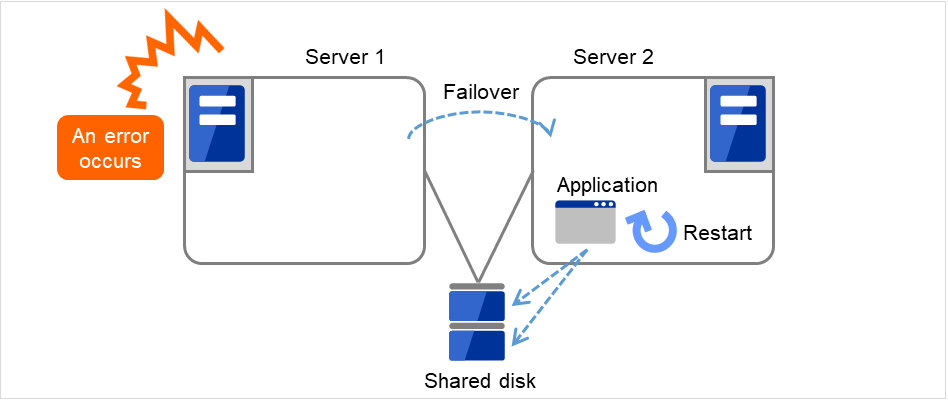
Fig. 3.25 Restarting the application
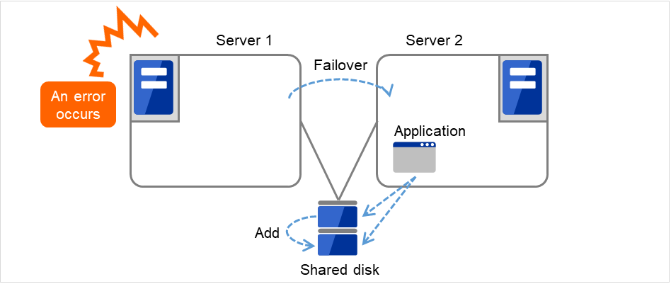
Fig. 3.26 Adding resources dynamically
3.3.1.5. Note 5: Mutual interference and compatibility with applications
Sometimes mutual interference between applications and EXPRESSCLUSTER functions or the operating system functions required to use EXPRESSCLUSTER functions prevents applications or EXPRESSCLUSTER from working properly.
Generally, you can assume when an application that is started up by EXPRESSCLUSTER is started, the switchable partition or data partition to which it should access is already accessible.
3.3.2. Configuration relevant to the notes
What you need to consider differs depending on which standby cluster system is selected for an application. Following is the notes for each cluster system. The numbers corresponds to the numbers of notes (1 through 5) described below:
Note for uni-directional standby [Active-Standby]: 1, 2, 3, and 5
Note for multi-directional standby [Active-Active]: 1, 2, 3, 4, and 5
- Note for co-existing behaviors: 5(Applications co-exist and run. The cluster system does not fail over the applications.)
3.3.3. Solutions to the problems relevant to the notes
Problems |
Solution |
Note to refer |
|---|---|---|
When an error occurs while updating a data file, the application does not work properly on the standby server. |
Modify the program, or add/modify script source to run a process to recover being updated during failover. |
Note 1: Data recovery after an error |
The application keeps accessing shared disk or mirror disk for a certain period of time even after it is stopped. |
Execute the sleep command during stop script execution. |
Note 2: Application termination |
The same application cannot be started more than once on one server. |
In multi-directional operation, reboot the application at failover and pass the shared data. |
Note 3: Location to store the data |
3.3.4. How to determine a cluster topology
Carefully read this chapter and determine the cluster topology that suits your needs:
When to start which application
Actions that are required at startup and failover
Data to be placed in switchable partitions or data partitions
3.4. Planning a failover group
A failover group (hereafter referred to as group) is a set of resources required to perform an independent operation service in a cluster system. Failover takes place by the unit of group. A group has its own group name and the attribute of the group resources.
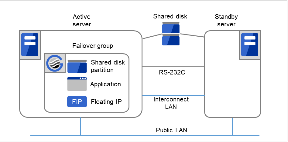
Fig. 3.27 Failover group and group resources
Resources in each group are handled by the unit of the group. If a failover occurs in group1 that has disk resource1 and Floating IP resource1, a failover of Disk resource1 and a failover of Floating IP1 are concurrent. (Disk resource 1 never fails over alone.) Likewise, a resource is never included in other groups.
3.5. Considering group resources
For a failover to occur in a cluster system, a group that works as a unit of failover must be created. A group consists of group resources. In order to create an optimal cluster, you must understand what group resources to be added to the group you create, and have a clear vision of your operation.
See also
For details on each resource, refer to "Group resource details" in the "Reference Guide".
The following are currently supported group resources:
Group Resource Name |
Abbreviation |
|---|---|
Application resource |
appli |
CIFS resource |
cifs |
Dynamic DNS resource |
ddns |
Floating IP resource |
fip |
Hybrid disk resource |
hd |
Mirror disk resource |
md |
NAS resource |
nas |
Registry synchronization resource |
regsync |
Script resource |
script |
Disk resource |
sd |
Service resource |
service |
Print spooler resource |
spool |
Virtual computer name resource |
vcom |
Virtual IP resource |
vip |
VM resource |
vm |
AWS Elastic IP resource |
awseip |
AWS Virtual IP resource |
awsvip |
AWS DNS resource |
awsdns |
Azure probe port resource |
azurepp |
Azure DNS resource |
azuredns |
Google Cloud virtual IP resource |
gcvip |
Google Cloud DNS resource |
gcdns |
Oracle Cloud virtual IP resource |
ocvip |
3.6. Understanding monitor resources
- Always monitors
Monitoring is performed from when the cluster is started up until it is shut down.
- Monitors while activated
Monitoring is performed from when a group is activated until it is deactivated.
See also
For the details of each resource, see "Monitor resource details" in the "Reference Guide".
The following are currently supported monitor resources:
Monitor Resource Name |
Abbreviation |
Always monitors |
Monitors While activated |
|---|---|---|---|
Application monitor resource |
appliw |
✓ |
|
CIFS monitor resource |
cifsw |
✓ |
|
DB2 monitor resource |
db2w |
✓ |
|
Dynamic DNS monitor resource |
ddnsw |
✓ |
|
Disk RW monitor resource |
diskw |
✓ |
|
Floating IP monitor resource |
fipw |
✓ |
|
FTP monitor resource |
ftpw |
✓ |
|
Custom monitor resource |
genw |
✓ |
|
Hybrid disk monitor resource |
hdw |
✓ |
|
Hybrid disk TUR monitor resource |
hdtw |
✓ |
|
HTTP monitor resource |
httpw |
✓ |
|
IMAP4 monitor resource |
imap4w |
✓ |
|
IP monitor resource |
ipw |
✓ |
✓ |
Mirror disk monitor resource |
mdw |
✓ |
|
Mirror connect monitor resource |
mdnw |
✓ |
|
NIC Link UP/Down monitor resource |
miiw |
✓ |
✓ |
Multi target monitor resource |
mtw |
✓ |
|
NAS monitor resource |
nasw |
✓ |
|
ODBC monitor resource |
odbcw |
✓ |
|
Oracle monitor resource |
oraclew |
✓ |
|
WebOTX monitor resource |
otxw |
✓ |
|
POP3 monitor resource |
pop3w |
✓ |
|
PostgreSQL monitor resource |
psqlw |
✓ |
|
Registry synchronization monitor resource |
regsyncw |
✓ |
|
Disk TUR monitor resource |
sdw |
✓ |
|
Service monitor resource |
servicew |
✓ |
|
SMTP monitor resource |
smtpw |
✓ |
|
Print spooler monitor resource |
spoolw |
✓ |
|
SQL Server monitor resource |
sqlserverw |
✓ |
|
Tuxedo monitor resource |
tuxw |
✓ |
|
Virtual computer name monitor resource |
vcomw |
✓ |
|
Virtual IP monitor resource |
vipw |
✓ |
|
WebSphere monitor resource |
wasw |
✓ |
|
WebLogic monitor resource |
wlsw |
✓ |
|
VM monitor resource |
vmw |
✓ |
|
Message receive monitor resource |
mrw |
✓ |
|
JVM monitor resource |
jraw |
✓ |
✓ |
System monitor resource |
sraw |
✓ |
|
Process resource monitor resource |
psrw |
✓ |
|
Process name monitor resource |
psw |
✓ |
✓ |
User mode monitor resource |
userw |
✓ |
|
AWS Elastic IP monitor resource |
awseipw |
✓ |
|
AWS Virtual IP monitor resource |
awsvipw |
✓ |
|
AWS AZ monitor resource |
awsazw |
✓ |
|
AWS DNS monitor resource |
awsdnsw |
✓ |
|
Azure probe port monitor resource |
azureppw |
✓ |
|
Azure load balance monitor resource |
azurelbw |
✓ |
|
Azure DNS monitor resource |
azurednsw |
✓ |
|
Google Cloud virtual IP monitor resource |
gcvipw |
✓ |
|
Google Cloud load balance monitor resource |
gclbw |
✓ |
|
Google Cloud DNS monitor resource |
gcdnsw |
✓ |
|
Oracle Cloud virtual IP monitor resource |
ocvipw |
✓ |
|
Oracle Cloud load balance monitor resource |
oclbw |
✓ |
3.7. Understanding heartbeat resources
Servers in a cluster system monitor whether or not other servers in the cluster are active.
Kernel mode LAN heartbeat (primary interconnect)
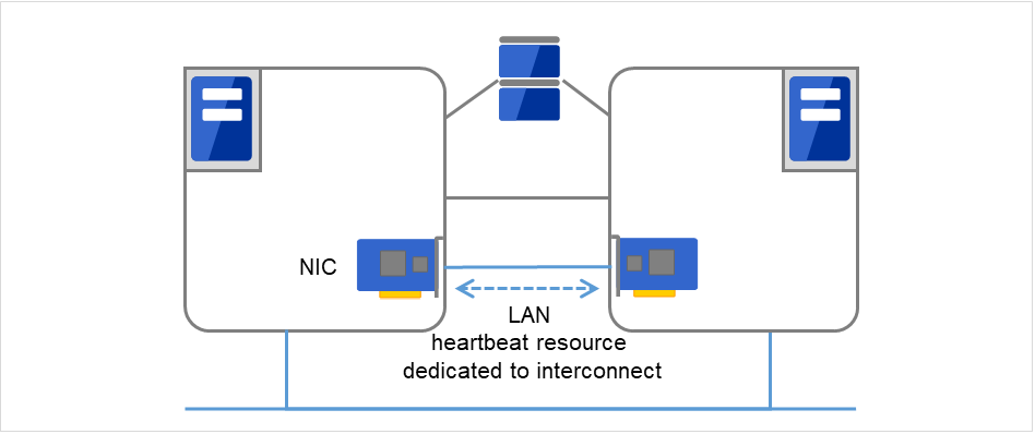
Fig. 3.28 Kernel mode LAN heartbeat (primary interconnect)
Kernel mode LAN heartbeat (secondary interconnect)
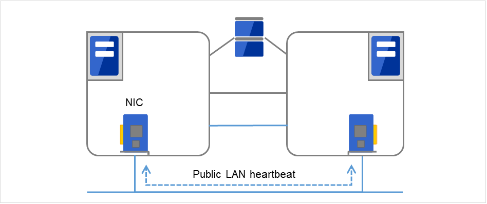
Fig. 3.29 Kernel mode LAN heartbeat (secondary interconnect)
BMC heartbeat
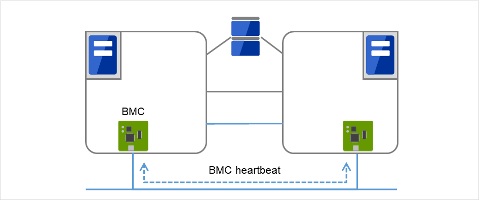
Fig. 3.30 BMC heartbeat
Witness heartbeat
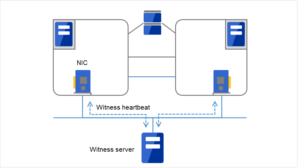
Fig. 3.31 Witness heartbeat
Type of Heartbeat Resource |
Abbreviation |
Functional Overview |
|---|---|---|
Kernel mode LAN heartbeat resource (1), (2) |
lankhb |
A kernel mode module uses a LAN to monitor whether or not servers are active. |
BMC heartbeat (3) |
bmchb |
A module uses BMC to monitor whether or not servers are active. |
Witness heartbeat resource (4) |
witnesshb |
A module uses the Witness server to monitor whether or not servers are active. |
At least one kernel mode LAN heartbeat resource needs to be set. Setting up more than two is recommended.
Set up one or more kernel mode LAN heartbeat resource to be used among all the servers.
3.8. Understanding network partition resolution resources
Network partitioning refers to the status where all communication channels have problems and the network between servers is partitioned.
In a cluster system that is not equipped with solutions for network partitioning, a failure on a communication channel cannot be distinguished from an error on a server. This can cause data corruption brought by access from multiple servers to the same resource. EXPRESSCLUSTER, on the other hand, distinguishes a failure on a server from network partitioning when the heartbeat from a server is lost. If the lack of heartbeat is determined to be caused by the server failure, the system performs a failover by activating each resource and rebooting applications on a server running normally. When the lack of heartbeat is determined to be caused by network partitioning, emergency shutdown is executed because protecting data has higher priority over continuity of the operation. Network partitions can be resolved by the following methods:
COM method
Available in a 2-nodes cluster
Cross cables are needed.
The COM channel is used to check if the other server is active and then to determine whether or not the problem is caused by network partitioning.
If a server failure occurs when there is a failure in the COM channel (such as COM port and serial cross cable), resolving the network partition fails. Thus, a failover does not take place. Emergency shutdown takes place in servers including the normal server.
If a failure occurs on all network channels when the COM channel is working properly, it is regarded as network partitions. In this case, emergency shutdown takes place in all servers except the master server.
If a failure occurs on all network channels when there is a problem in the COM channel (such as COM port and serial cross cable), emergency shutdown takes in all servers excluding the master server.
If failures occur in all network channels between cluster server and the COM channel simultaneously, both active and standby servers fail over. This can cause data corruption due to access to the same resource from multiple servers.
PING method
A device that is always active to receive and respond to the ping command (hereafter described as ping device) is required.
More than one ping device can be specified.
When the heartbeat from the other server is lost, but the ping device is responding to the ping command, it is determined that the server without heartbeat has failed and a failover takes place. If there is no response to the ping command, the local server is isolated from the network due to network partitioning, and emergency shutdown takes place. This will allow a server that can communicate with clients to continue operation even if network partitioning occurs.
When the status where no response returns from the ping command on all servers continues before the heartbeat is lost, which is caused by a failure in the ping device, the network partitions cannot be resolved. If the heartbeat is lost in this status, a failover takes place in all servers. Because of this, using this method in a cluster with a shared disk can cause data corruption due to access to a resource from multiple servers.
HTTP method
A Web server that is always active is required.
When the heartbeat from the other server is lost, but there is a response to an HTTP HEAD request, it is determined that the server without heartbeat has failed and a failover takes place. If there is no response to an HTTP HEAD request, it is determined that the local server is isolated from the network due to network partitioning, and an emergency shutdown takes place. This will allow a server that can communicate with clients to continue operation even if network partitioning occurs.
When there remains no response to an HTTP HEAD request before the heartbeat is lost, which is caused by a failure in Web server, the network partitions cannot be resolved. If the heartbeat is lost in this status, emergency shutdowns occur in all the servers.
DISK method
Available to a cluster that uses a shared disk.
A dedicated disk partition (disk heartbeat partition) is required on the shared disk.
Network partitioning is determined by writing data periodically on a shared disk and calculating the last existing time of the other server.
If the heartbeat from other server is lost while there is any failure in the shared disk or channel to the shared disk (such as SCSI bus), resolving network partitions fails, which means failover does not take place. In this case, emergency shutdown takes place in servers working properly.
If failures occur on all network channels while the shared disk is working properly, a network partition is detected. Then failover takes place in the master server and a server that can communicate with the master server. Emergent shutdown takes place in the rest of servers.
Compared to the other methods, the time needed to resolve network partitions is longer in the shared disk method because the delay of the disk I/O must be taken into account. The time is about twice as long as the heartbeat time-out and disk I/O wait time.
If the I/O time to the shared disk is longer than the disk I/O wait time, the resolving network may time out, and failover may not take place.
Note
Shared DISK method cannot be used if VERITAS Storage Foundation is used.
COM + DISK method
This is a method that combines the COM method and the DISK method. This method is available in a cluster that uses a shared disk with two nodes.
This method requires serial cross cables. A dedicated disk partition (disk heartbeat partition) must be allocated on the shared disk.
When the COM channel (such as a COM port and serial cross cable) is working properly, this method works in the same way as the COM method. When an error occurs on the COM channel, this method switches to the shared DISK method. This mechanism offers higher availability than the COM method. The method also achieves network partition resolving faster than the DISK method.
Even if failures occur on all network channels between cluster servers and the COM channel simultaneously, emergency shutdown takes place at least on one of the servers. This will prevent data corruption.
PING + DISK method
This is a method that the PING method and the DISK are combined.
This method requires a device (a ping device) that can always receive the ping command and return response. You can specify more than one ping device. This method also requires the dedicated disk partition (disk heartbeat partition) on the shared disk.
This method usually works in the same way as the PING method. However, if the state where a response to the ping command on all servers does not return continues, due to a failure of the ping device before the heartbeat is lost, the method is switched to the DISK method. If the servers using the NP resolution resources of the PING method and those using the NP resolution resources of the DISK method do not match (such as when the PING method resources are used by all servers, but the DISK method resources are used only by some servers connected to a shared disk), the resources of these two types work independently. Therefore, the DISK method works as well, regardless of the state of the ping device.
If the heartbeat from the other server is lost while there is a failure in the shared disk and/or a path to the shared disk, emergency shutdown takes place even if there is response to the ping command.
Majority method
This method can be used in a cluster with three or more nodes.
This method prevents data corruption caused by the Split Brain syndrome by shutting down a server that can no longer communicate with the majority of the servers in the entire cluster because of network failure. When communication with exactly half of the servers in the entire cluster is failing, emergency shutdown takes place in a server that cannot communicate with the master server.
When more than half of the servers are down, the rest servers running properly also go down.
If all servers are isolated due to a hub error, all servers go down.
Not solving the network partition
This method can be selected in a cluster that does not use any disk resource (a shared disk).
If a failure occurs on all network channels between servers in a cluster, all servers failover.
The following are the recommended methods to resolve the network partition:
The ping + shared disk method is recommended for a cluster that uses a shared disk with three or more nodes. When using the hybrid type, use the PING + DISK method for the servers connected to the DISK, and use only the PING method for the servers not connected to the shared disk.
The PING method is recommended for a cluster with three or more nodes but without a shared disk.
The COM + DISK method or the PING + DISK method is recommended for a cluster that uses a shared disk with two nodes.
The COM method or the PING method is recommended for a cluster with two nodes but without a shared disk.
The HTTP method is recommended for a cluster that uses the Witness heartbeat resource but does not use a shared disk.
Method to resolve a network partition |
Number of nodes |
Required hardware |
Circumstance where failover cannot be performed |
When all network channels are disconnected |
Circumstance where both servers fail over |
Time required to resolve network partition |
|---|---|---|---|---|---|---|
COM |
2 |
Serial cable |
COM error |
The master server survives |
COM error and network disconnection occur simultaneously |
0 |
DISK |
No limit |
Shared disk |
Disk error |
The master server survives |
None |
Time calculated by the heartbeat timeout and disk I/O wait time is needed |
PING |
No limit |
Device to receive the ping command and return a response |
None |
Server that responses to the ping command survives |
All networks are disconnected after the ping command timeouts the specified times consecutively |
0 |
HTTP |
No limit |
Web server |
Web server failure |
A server that can communicate with the Web server survives |
None |
0 |
COM +
DISK
|
2 |
Serial cables shared disk |
COM error and
disk error
|
The master server survives |
None |
0 |
PING +
DISK
|
No limit |
Device to receive the ping command and return response
Shared disk
|
None |
Server responding to the ping command survives |
None |
0 |
Majority |
3 or more |
None |
Majority of servers go down |
A server that can communicate with majority of servers survives |
None |
0 |
None |
No limit |
None |
None |
All servers fail over |
All networks are disconnected |
0 |
4. Installing EXPRESSCLUSTER
This chapter provides instructions for installing EXPRESSCLUSTER.
This chapter covers:
4.1. Steps from Installing EXPRESSCLUSTER to creating a cluster
The following describes the steps from installing EXPRESSCLUSTER, license registration, cluster system creation, to verifying the cluster system status.
Before proceeding to the following steps, make sure to read "2. Determining a system configuration" and "3. Configuring a cluster system" and check system requirements and the configuration of a cluster.
Install the EXPRESSCLUSTER Server
Install the EXPRESSCLUSTER Server, which is the core EXPRESSCLUSTER module, to each server that constitutes a cluster. When installing the Server, a license registration is performed as well. (See "4. Installing EXPRESSCLUSTER.")Reboot the serverCreate the cluster configuration data using Cluster WebUI
Create the cluster configuration data by using the Cluster WebUI. (See "6. Creating the cluster configuration data.")
Create a cluster
Create a cluster by applying the cluster configuration data created with theCluster WebUI. (See "6. Creating the cluster configuration data".)
Verify the cluster status using the Cluster WebUI
Verify the status of a cluster that you have created using the Cluster WebUI. (See "7. Verifying a cluster system.")
See also
You need to refer to the "Reference Guide" as needed by following the steps written in this guide to perform operation following this guide. For the latest information on the system requirements and lease information, refer to "Installation requirements for EXPRESSCLUSTER" and "Latest version information" in the "Getting Started Guide".
4.2. Installing the EXPRESSCLUSTER Server
The EXPRESSCLUSTER Server consists of the following system services:
Service Display Name |
Service Name |
Description |
Startup Type |
Service Status (usual) |
|---|---|---|---|---|
EXPRESSCLUSTER |
clpstartup |
EXPRESSCLUSTER |
Automatic |
Running |
EXPRESSCLUSTER API |
clprstd |
Control of the EXPRESSCLUSTER RESTful API |
Automatic |
Stopped |
EXPRESSCLUSTER Disk Agent |
clpdiskagent |
Shared disk, mirror disk, hybrid disk control |
Manual |
Running |
EXPRESSCLUSTER Event |
clpevent |
Event log output |
Automatic |
Running |
EXPRESSCLUSTER Information Base |
clpibsv |
Cluster information management |
Automatic |
Running |
EXPRESSCLUSTER Java Resource Agent |
clpjra |
Java Resource Agent |
Manual |
Stopped |
EXPRESSCLUSTER Manager |
clpwebmgr |
WebManager Server |
Automatic |
Running |
EXPRESSCLUSTER Old API Support |
clpoldapi |
Compatible API process |
Automatic |
Running |
EXPRESSCLUSTER Server |
clppm |
EXPRESSCLUSTER Server |
Automatic |
Running |
EXPRESSCLUSTER System Resource Agent |
clpsra |
System Resource Agent |
Manual |
Stopped |
EXPRESSCLUSTER Transaction |
clptrnsv |
Communication process |
Automatic |
Running |
EXPRESSCLUSTER Web Alert |
clpwebalt |
Alert synchronization |
Automatic |
Running |
Note
The status of EXPRESSCLUSTER Java Resource Agent will be "Running" when JVM monitor resource is set.
Note
The status of EXPRESSCLUSTER System Resource Agent will be "Running" When the system monitor resource or the process resource monitor resource is set or Collect the System Resource Information is checked on the Monitor tab in Cluster Properties.
4.2.1. Installing the EXPRESSCLUSTER Server for the first time
Install the EXPRESSCLUSTER X on all servers that constitute the cluster by following the procedures below.
Important
When a shared disk is used, make sure not to start more than one OS on servers connected to the shared disk before installing EXPRESSCLUSTER. Data on the shared disk may be corrupted.
Note
Install the EXPRESSCLUSTER Server using Administrator account.
Note
When installing EXPRESSCLUSTER server, Windows media sense function which is the function to deactivate IP address due to disconnection of the cable at link down occurrence will be disabled.
Note
Insert the installation CD-ROM into the CD-ROM drive.
After the menu window is displayed, select EXPRESSCLUSTER for Windows.
Note
If the menu window does not open automatically, double-click the menu.exe in the root folder of the CD-ROM.
Select EXPRESSCLUSTER X 4.3 for Windows.
The NEC EXPRESSCLUSTER Setup window is displayed. Click Next.
The Choose Destination Location dialog box is displayed. When changing the install destination, click Browse to select a directory.
In the Ready to Install the Program window, click Install to start installing.
After the installation is completed, click Next without changing the default value in Port Number.
Note
The port number configured here needs to be configured again when creating the cluster configuration data. For details on port number, refer to "Parameter details" in the "Reference Guide".
In Filter Settings of Shared Disk, right-click SCSI controller or HBA connected to a shared disk, and click Filtering. Click Next.
Important
When a shared disk is used, configure filtering settings to the SCSI controller or HBA to be connected to the shared disk. If the shared disk is connected without configuring filtering settings, data on the shared disk may be corrupted. When the disk path is duplicated, it is necessary to configure the filter for all the HBAs physically connected with the shared disk though it may look the shared disk is connected to only one HBA.
Important
When using mirror disk resources, do not perform filtering settings for SCSI controller/HBA which an internal disk for the mirroring target is connected. If the filter is activated on mirror disk resources, starting mirror disk resources fails. However, it is essential to perform filtering settings when shared disks are expected to consist mirroring.
The window that shows the completion of setting is displayed. Click Yes.
License Manager is displayed. Click Register to register the license. For detailed information on the registration procedure, refer to "5. Registering the license" in this guide.
Click Finish to close the License Manager dialog box.
The Complete InstallShiled Wizard dialog box is displayed. Select Restarting and click Finish. The server will be rebooted.
Note
When a shared disk is used, it cannot be accessed due to access restriction after OS reboot.
4.2.2. Installing the EXPRESSCLUSTER Server in Silent Mode
Note
Installation in silent mode is not available for a shared disk configuration. For a shared disk configuration, install the EXPRESSCLUSTER Server by referring to "Installing the EXPRESSCLUSTER Server for the first time."
Note
Install the EXPRESSCLUSTER Server using Administrator account.
Note
When installing EXPRESSCLUSTER server, Windows media sense function which is the function to deactivate IP address due to disconnection of the cable at link down occurrence will be disabled.
Note
Preparation
If you want to change the installation folder (default:
C:\Program Files\EXPRESSCLUSTER), create a response file in advance following the procedure below.
Windows\4.3\common\server\x64\response\setup_inst_en.issOpen the response file (setup_inst_en.iss) with a text editor, then change the folder written in the szDir line.
Count=4
Dlg1={8493CDB6-144B-4330-B945-1F2123FADD3A}-SdAskDestPath-0
Dlg2={8493CDB6-144B-4330-B945-1F2123FADD3A}-SdStartCopy2-0
Dlg3={8493CDB6-144B-4330-B945-1F2123FADD3A}-SdFinishReboot-0
[{8493CDB6-144B-4330-B945-1F2123FADD3A}-SdWelcome-0]
Result=1
[{8493CDB6-144B-4330-B945-1F2123FADD3A}-SdAskDestPath-0]
szDir=C:\Program Files\CLUSTERPRO
Result=1
Installation procedure
Windows\4.3\common\server\x64\silent-install.batin the installation CD-ROM.* When installing the EXPRESSCLUSTER Server in the default directory (C:\Program Files\EXPRESSCLUSTER), omit <Path of response file>.Restart the server.
4.2.3. Upgrading EXPRESSCLUSTER Server from the previous version
Before starting the upgrade, read the following notes.
It is possible to upgrade version from EXPRESSCLUSTER X 1.0, 2.0, 2.1, 3.0, 3.1, 3.2 or 3.3 to EXPRESSCLUSTER X 4.3.
You need CD-ROM contains setup files and software licenses for EXPRESSCLUSTER X 4.3.
You cannot use the cluster configuration data that was created by using EXPRESSCLUSTER X higher than EXPRESSCLUSTER X in use.
The cluster configuration data that was created by using EXPRESSCLUSTER X 1.0, 2.0, 2.1, 3.0, 3.1, 3.2, 3.3,4.0,4.1,4.2 or 4.3 for Windows is available for EXPRESSCLUSTER X in use.
If mirror disk resources or hybrid disk resources are set, cluster partitions require space of 1 GB or larger. And also, executing full copy of mirror disk resources or hybrid disk resources is required.
If mirror disk resources or hybrid disk resources are set, it is recommended to backup data in advance. For details of a backup procedure, refer to "Performing a snapshot backup" in "The system maintenance information" in the "Maintenance Guide".
EXPRESSCLUSTER Server must be upgraded with the account having the Administrator's privilege.
See also
For the update from X 4.0/4.1/4.2 to X 4.3, see "Update Procedure Manual".
The following procedures explain how to upgrade from EXPRESSCLUSTER X 1.0, 2.0, 2.1, 3.0, 3.1, 3.2 or 3.3 to EXPRESSCLUSTER X 4.3.
Before upgrading, confirm that the servers in the cluster and all the resources are in normal status by using WebManager or the command.
Save the current cluster configuration file with the Builder or clpcfctrl command. For details about saving the cluster configuration file with clpcfctrl command, refer to "Backing up the cluster configuration data (clpcfctrl --pull)" of "Creating a cluster and backing up configuration data (clpcfctrl command)" in "EXPRESSCLUSTER command reference" in the "Reference Guide".
When the EXPRESSCLUSTER Server service of the target server is configured as Auto Startup, change the settings to Manual Startup.
Shut down the entire cluster.
Start only one server, and uninstall the EXPRESSCLUSTER Server. For details about uninstalling the EXPRESSCLUSTER Server, refer to "10.1.1. Uninstalling the EXPRESSCLUSTER Server" in "10. Uninstalling and reinstalling EXPRESSCLUSTER" in this guide.
Install the EXPRESSCLUSTER X 4.3 on the server from which was uninstalled old version of the EXPRESSCLUSTER server in the step 5, and then register the license as necessary. For details about how to install the EXPRESSCLUSTER Server, refer to "4.2. Installing the EXPRESSCLUSTER Server" in "4. Installing EXPRESSCLUSTER" in this guide.
Shut down the server on which was installed the EXPRESSCLUSTER X 4.3 in the step 6.
Perform the steps 5 to 7 on each server.
Start all the servers.
If mirror disk resources or hybrid disk resources are set, allocate cluster partition (The cluster partition should be 1 GB or larger).
- Access the below URL to start the WebManager.
http://actual IP address of an installed server:29003/main.htm
Import the cluster configuration file which was saved in the step 2.If the drive letter of the cluster partition is different from the configuration, modify the configuration. And regarding the groups which mirror disk resources or hybrid disk resources belong to, if Startup Attribute is Auto Startup on the Attribute tab of Group Properties, change it to Manual Startup.In order to use the values of Maximum Failover Count which were set before version up EXPRESSCLUSTER, set Cluster Properties -> Extension tab -> Failover Count Method to Cluster from Server. - Upload the cluster configuration data with the Cluster WebUI.When the message "There is difference between the disk information in the configuration information and the disk information in the server. Are you sure you want automatic modification?" appears, select Yes.If the fixed-term license is used, run the following command.
clplcnsc --distribute
Start the cluster on Cluster WebUI.
If mirror disk resources or hybrid disk resources are set, from the mirror disk list, execute a full copy assuming that the server with the latest data is the copy source.
Start the group and confirm that each resource starts normally.
If Startup Attribute was changed from Auto Startup to Manual Startup in step 11, use the config mode of Cluster WebUI to change this to Auto Startup. Then, click Apply the Configuration File to apply the cluster configuration data to the cluster.
This completes the procedure for upgrading the EXPRESSCLUSTER Server. Check that the servers are operating normally as the cluster by the clpstat command or Cluster WebUI
4.2.4. Setting up the SNMP linkage function manually
Note
If you are using only the SNMP trap transmission function, you do not need to perform this procedure.
When the Windows SNMP Service has not been installed, follow the procedure below to manually register the SNMP linkage function.
Note
Use an Administrator account to perform the registration.
Install the Windows SNMP Service.
Stop the Windows SNMP Service.
- Register the SNMP linkage function of EXPRESSCLUSTER with the Windows SNMP Service.3-1. Start the registry editor.3-2. Open the following key:
HKEY_LOCAL_MACHINE\SYSTEM\CurrentControlSet\Services\SNMP\Parameters\ExtensionAgents
3-3. Specify the following to create a string value in the opened key:Value name : mgtmibValue type : REG_SZValue data :SOFTWARE\NEC\EXPRESSCLUSTER\SnmpAgent\mgtmib\CurrentVersion3-4. Exit the registry editor. Start the Windows SNMP Service.
Note
Specify the settings required for SNMP communication on the Windows SNMP Service.
5. Registering the license
To run EXPRESSCLUSTER as a cluster system, you need to register the license. This chapter describes how to register an EXPRESSCLUSTER license.
This chapter covers:
5.1. Registering the license
EXPRESSCLUSTER licenses can be registered during installation, as well as be added or deleted after installation.
5.1.1. Registering the CPU license
For the following CPU licenses of the EXPRESSCLUSTER, register the license to the master server of a cluster.
Main Products
EXPRESSCLUSTER X 4.3 for Windows
EXPRESSCLUSTER X SingleServerSafe 4.3 for Windows
EXPRESSCLUSTER X SingleServerSafe for Windows Upgrade
5.1.2. Registering the node license
For the following node licenses of the EXPRESSCLUSTER, register the license to each cluster server.
Main Products
EXPRESSCLUSTER X 4.3 for Windows VM
EXPRESSCLUSTER X SingleServerSafe 4.3 for Windows VM
EXPRESSCLUSTER X SingleServerSafe for Windows VM Upgrade
Optional Products
EXPRESSCLUSTER X Replicator 4.3 for Windows
EXPRESSCLUSTER X Replicator DR 4.3 for Windows
EXPRESSCLUSTER X Replicator DR 4.3 Upgrade for Windows
EXPRESSCLUSTER X Database Agent 4.3 for Windows
EXPRESSCLUSTER X Internet Server Agent 4.3 for Windows
EXPRESSCLUSTER X Application Server Agent 4.3 for Windows
EXPRESSCLUSTER X Java Resource Agent 4.3 for Windows
EXPRESSCLUSTER X System Resource Agent 4.3 for Windows
EXPRESSCLUSTER X Alert Service 4.3 for Windows
Note
If the licenses for optional products have not been installed, the resources and monitor resources corresponding to those licenses are not shown in the list on the Cluster WebUI.
There are two ways of license registration; specifying the license file and using the information on the license sheet.
Entering the license information attached to the license product to register the license. Refer to "5.1.4. Registering the license by entering the license information".
Specifying the license file to register the license. Refer to "5.1.5. Registering the license by specifying the license file".
5.1.3. Notes on the CPU license
Notes on using the CPU license are as follows:
After registration of the CPU license on the master server, Cluster WebUI on the master server must be used in order to edit and reflect the cluster configuration data as described in "6. Creating the cluster configuration data".
5.1.4. Registering the license by entering the license information
EXPRESSCLUSTER CPU license
You have the license sheet you officially obtained from the sales agent. The values on this license sheet are used for registration.
You have the administrator privileges to log in the server intended to be used as master server in the cluster.
EXPRESSCLUSTER node license
You have the license sheet you officially obtained from the sales agent. The number of license sheets you need is as many as the number of servers on which the product will be used. The values on this license sheet are used for registration.
You have the administrator privileges to log in the server on which you intend to use the product.
On the Start menu, click License Manager of the EXPRESSCLUSTER Server.
In the License Manager dialog box, click Register.
In the window to select a license method, select Register with License Information.
In the Product selection dialog box, select the product category, and click Next.
In the License Key Entry dialog box, enter the serial number and license key of the license sheet. Click Next.
Confirm what you have entered on the License Registration Confirmation dialog box. Click Next.
Make sure that the pop-up message, "The license was registered." is displayed. If the license registration fails, start again from the step 2.
5.1.5. Registering the license by specifying the license file
The following describes how to register the license by specifying the license.
Before you register the license, check that:
EXPRESSCLUSTER CPU license
You have the administrator privileges to log in the server intended to be used as master server in the cluster.
The license file is located in the server intended to be used as master server in the cluster.
EXPRESSCLUSTER node license
You have the administrator privileges to log in the server on which you intend to use the product.
The license file is located in the server in which you intend to use products among servers that constitute a cluster system.
On the Start menu, click License Manager of the EXPRESSCLUSTER Server.
In the License Manager dialog box, click Register.
In the window to select a license method is displayed, select Register with License File.
In the License File Specification dialog box, select the license file to be registered and then click Open.
The message confirming registration of the license is displayed. Click OK.
Click Finish to close the license manager.
5.2. Referring and/or deleting the license
5.2.1. How to refer to and/or delete the registered license
The following procedure describes how to refer to and delete the registered license.
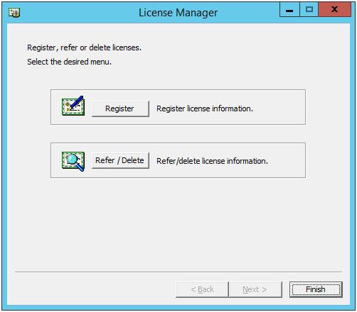
On the Start menu, click License Manager of the EXPRESSCLUSTER Server.
In the License Manager dialog box, click Refer / Delete.
The registered licenses are listed.
Select the license to delete and click Delete.
The confirmation message to delete the license is displayed. Click OK.
5.3. Registering the fixed term license
The fixed term license applies to the EXPRESSCLUSTER X 4.3 for Windows and optional products as shown below. Among servers that constitute the cluster, use the master server to register the fixed term license.
Main Products
EXPRESSCLUSTER X 4.3 for Windows
Optional Products
EXPRESSCLUSTER X Replicator 4.3 for Windows
EXPRESSCLUSTER X Replicator DR 4.3 for Windows
EXPRESSCLUSTER X Database Agent 4.3 for Windows
EXPRESSCLUSTER X Internet Server Agent 4.3 for Windows
EXPRESSCLUSTER X Application Server Agent 4.3 for Windows
EXPRESSCLUSTER X Java Resource Agent 4.3 for Windows
EXPRESSCLUSTER X System Resource Agent 4.3 for Windows
EXPRESSCLUSTER X Alert Service 4.3 for Windows
Note
If the licenses for optional products have not been installed, the resources and monitor resources corresponding to those licenses are not shown in the list on the Cluster WebUI.
5.3.1. Notes on the fixed term license
Notes on using the fixed term license are as follows:
The fixed term license cannot be registered to serveral of the servers constituting the cluster to operate them.
After registration of the license on the master server, Cluster WebUI on the master server must be used in order to edit and reflect the cluster configuration data as described in "6. Creating the cluster configuration data".
The number of the fixed term license must be larger than the number of the servers constituting the cluster.
After starting the operation of the cluster, additional fixed term license must be registered in the master server.
Once enabled, the fixed term license cannot be reregistered despite its validity through the license/server removal or the server replacement.
5.3.2. Registering the fixed term license by specifying the license file
You have the administrator privileges to log in the server intended to be used as master server in the cluster.
The license files for all the products you intend to use are stored in the server that will be set as a master server among servers that constitute the cluster system.
Follow the following steps to register all the license files for the products to be used. If you have two or more license files for the same product in preparation for the expiration, execute the command to register the extra license files in the same way as the following steps.
On the Start menu, click License Manager of the EXPRESSCLUSTER Server.
In the License Manager dialog box, click Register.
In the window to select a license method is displayed, select Register with License File.
In the License File Specification dialog box, select the license file to be registered and then click Open.
The message confirming registration of the license is displayed. Click OK.
Click Finish to close the license manager.
5.4. Referring and/or deleting the fixed term license
5.4.1. How to refer to and/or delete the registered fixed term license
The procedure for referring and/or deleting the registered fixed term license is the same as that described in "5.2.1. How to refer to and/or delete the registered license".
6. Creating the cluster configuration data
In EXPRESSCLUSTER, data that contains information on how a cluster system is configured is called "cluster configuration data."This data is created using the Cluster WebUI. This chapter provides the information on how to start the Cluster WebUI and the procedures to create the cluster configuration data using the Cluster WebUI with a sample cluster configuration.
This chapter covers:
6.1. Creating the cluster configuration data
Creating the cluster configuration data is performed by using the config mode of Cluster WebUI, the function for creating and modifying cluster configuration data.
Start the Cluster WebUI accessed from the management PC and create the cluster configuration data. The cluster configuration data will be applied in the cluster system by the Cluster WebUI.
6.2. Starting up the Cluster WebUI
Accessing to the Cluster WebUI is required to create cluster configuration data. This section describes the overview of the Cluster WebUI, and how to create cluster configuration data.
See also
For the system requirements of the Cluster WebUI, refer to "Installation requirements for EXPRESSCLUSTER" in the Getting Started Guide.
6.2.1. What is Cluster WebUI?
The Cluster WebUI is a function for setting up the cluster, monitoring its status, starting up or stopping servers and groups, and collecting cluster operation logs through a Web browser. The overview of the Cluster WebUI is shown in the following figures.
EXPRESSCLUSTER Server (Main module)
Cluster WebUI
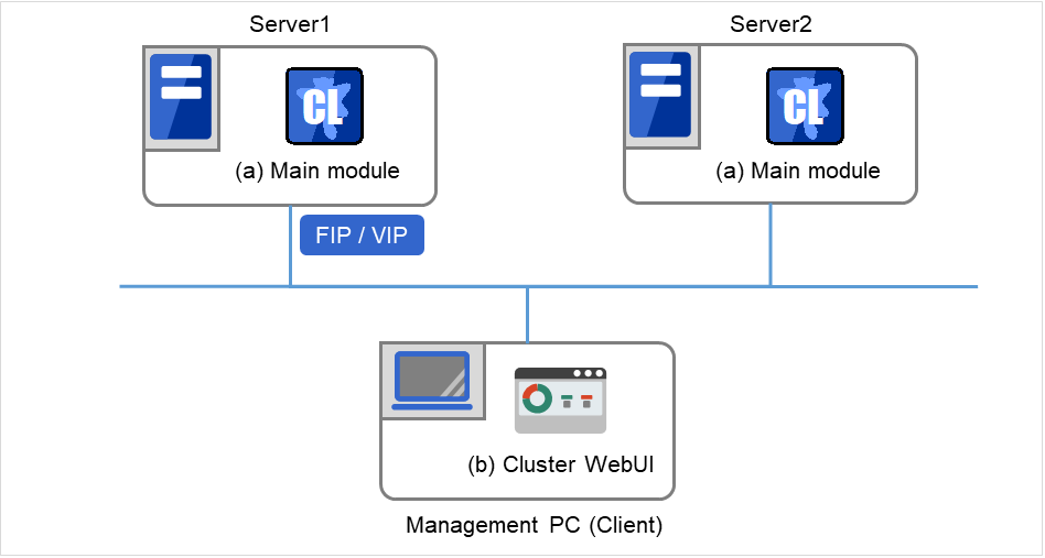
Fig. 6.1 Cluster WebUI
This figure shows two servers with EXPRESSCLUSTER installed. You can display the Cluster WebUI screen, by using a Web browser on the Management PC to access one of the servers. For this access, specify the management group's floating IP (FIP) address or virtual IP (VIP) address.
Specify the floating IP address or virtual IP address for accessing Cluster WebUI for the URL when connecting from a Web browser of the management PC.These addresses are registered as the resources of the management group. When the management group does not exist, you can specify the address of one of servers configuring the cluster (fixed address allocated to the server) to connect management PC with the server. In this case, the Cluster WebUI cannot acquire the status of the cluster if the server to be connected is not working.
6.2.2. Browsers supported by the Cluster WebUI
For information about evaluated Web browsers, refer to the "Getting Started Guide".
6.2.3. Starting the Cluster WebUI
The following describes how to start the Cluster WebUI.
Start your Web browser.
Enter the actual IP address and port number of the server where the EXPRESSCLUSTER Server is installed in the Address bar of the browser.
http://ip-address:port/
- ip-address
Specify the actual IP address of the first server in the cluster, because no management group exists just after the installation.
- port
Specify the same port number as that of WebManager specified during the installation (default: 29003).
The Cluster WebUI starts. To create the cluster configuration data, select Config Mode from the drop down menu of the tool bar.
Click Cluster generation wizard to start the wizard.
See also
https://ip-address:29003/
6.3. Checking the values to be configured
Before you create the cluster configuration data using Cluster generation wizard, check values you are going to enter. Write down the values to see whether your cluster is efficiently configured and there is no missing information.
6.3.1. Sample cluster environment
As shown in the below, this chapter uses a typical cluster configuration with two nodes and the hybrid disk configuration with three nodes.
When a shared disk with two nodes is used:
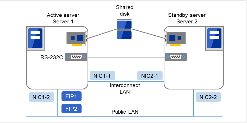
Fig. 6.2 Example of a 2-node cluster with a shared disk
FIP1
FIP2
NIC1-1
192.168.0.1
NIC1-2
10.0.0.1
NIC2-1
192.168.0.2
NIC2-2
10.0.0.2
Serial port
COM1
Shared disk
Drive letter of the disk heartbeat
E
File system
RAW
Drive letter of the switchable partition
F
File system
NTFS
When mirroring disks with two nodes are used:
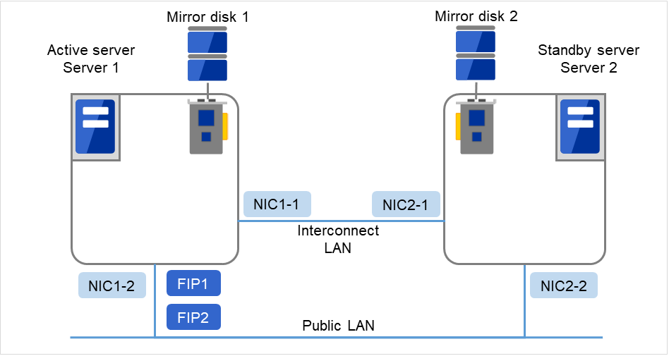
Fig. 6.3 Example of a 2-node cluster with mirror disks
FIP1
FIP2
NIC1-1
192.168.0.1
NIC1-2
10.0.0.1
NIC2-1
192.168.0.2
NIC2-2
10.0.0.2
Drive letter of the cluster partition
E
File system
RAW
Drive letter of the data partition
F
File system
NTFS
When mirror disk resources with remotely-constructed two nodes are used:
This configuration is an example for a layer-2 WAN, on which the same network address can be used between the locations.
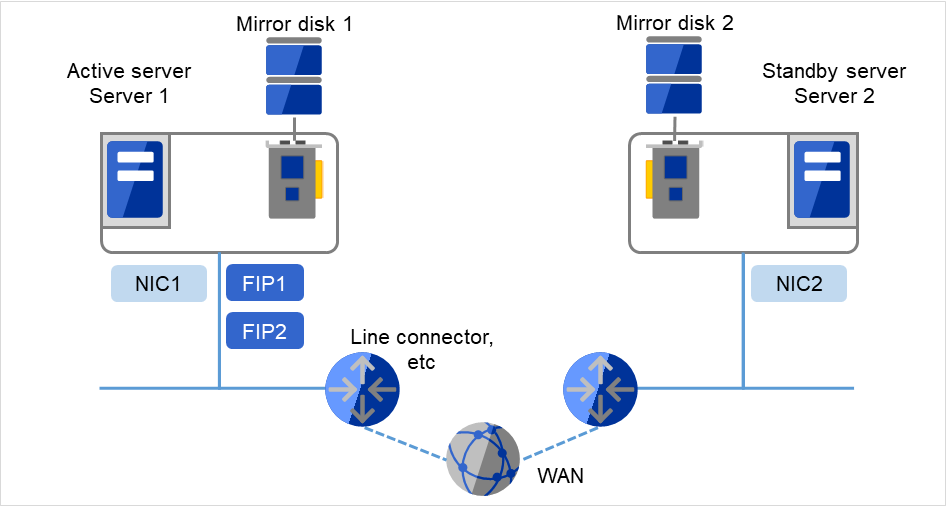
Fig. 6.4 Example of a 2-node cluster with a remote configuration using mirror disk resources
FIP1
FIP2
NIC1
10.0.0.1
NIC2
10.0.0.2
Drive letter of the cluster partition
E
File system
RAW
Drive letter of the data partition
F
File system
NTFS
When hybrid disks with three nodes are used:
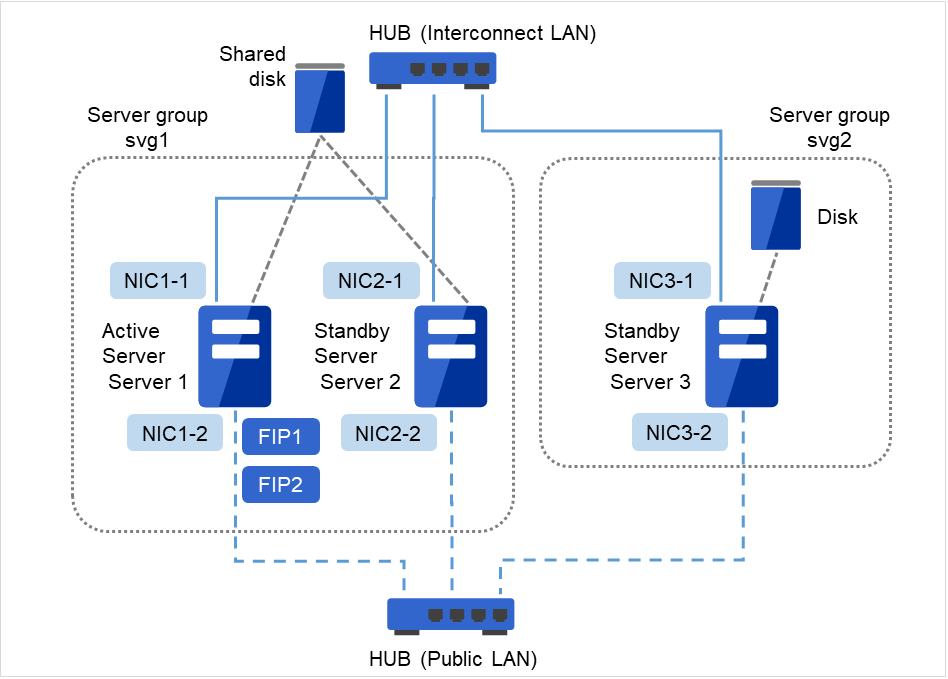
Fig. 6.5 Example of a 3-node cluster with hybrid disks
FIP1
FIP2
NIC1-1
192.168.0.1
NIC1-2
10.0.0.1
NIC2-1
192.168.0.2
NIC2-2
10.0.0.2
NIC3-1
192.168.0.3
NIC3-2
10.0.0.3
Shared disk
Drive letter of the partition for heartbeat
E
File system
RAW
Drive letter of the cluster partition
F
File system
RAW
Drive letter of the data partition
G
File system
NTFS
Disk
Drive letter of the cluster partition
F
File system
RAW
Drive letter of the data partition
G
File system
NTFS
The following table lists sample values of the cluster configuration data to achieve the cluster system shown above. The step-by-step instruction for creating the cluster configuration data with these values is provided in the following sections. When you actually set the values, you may need to modify them according to the cluster you are intending to create. For information on how you determine the values, refer to the Referenced Guide.
Example of configuration with 2 nodes
Target
Parameter
Value (For shared disk)
Value (For mirror disk)
Value (For remote construction)
Cluster configuration
Cluster name
Cluster
Cluster
Cluster
Number of servers
2
2
2
Number of management groups
1
1
-
Number of failover groups
1
1
1
Number of monitor resources
5
6
1
Heartbeat resources
Number of kernel mode LAN heartbeats
2
2
1
Server name
server1
server1
server1
Public IP address
10.0.0.1
10.0.0.1
10.0.0.1
Mirror connect I/F
-
192.168.0.1
10.0.0.1
HBA
HBA connected to a shared disk
-
-
Second server information
Server name
server2
server2
server2
192.168.0.2
192.168.0.2
10.0.0.2
10.0.0.2
10.0.0.2
-
Public IP address
10.0.0.2
10.0.0.2
10.0.0.2
Mirror connect I/F
-
192.168.0.2
10.0.0.2
HBA
HBA connected to a shared disk
-
-
First NP resolution resource
Type
COM
-
Ping
Ping target
-
-
10.0.0.254
Server1
COM1
-
Use
Server2
COM1
-
Use
Second NP resolution resource
Type
DISK
-
-
Ping target
-
-
-
Server1
E:
-
-
Server2
E:
-
-
Group for management (For the Cluster WebUI)
Type
cluster
cluster
cluster
Group name
ManagementGroup
ManagementGroup
ManagementGroup
Startup server
all servers
all servers
all servers
Number of group resources
1
1
1
Group resources for management 1
Type
Floating IP resource
Floating IP resource
floating IP resource
Group resource name
ManagementIP
ManagementIP
ManagementIP
IP address
10.0.0.11
10.0.0.11
10.0.0.11
Failover group
Type
failover
failover
failover
Group name
failover1
failover1
failover1
Startup server
server1 -> server2
server1 -> server2
server1 -> server2
Number of group resources
3
3
3
First group resources
Type
Floating IP resource
Floating IP resource
Floating IP resource
Group resource name
fip1
fip1
fip1
IP address
10.0.0.12
10.0.0.12
10.0.0.12
Second group resources
Type
Disk resource
Mirror disk resource
Mirror disk resource
Group resource name
sd1
md1
md1
Disk resource drive letter
F:
-
-
Mirror disk resource cluster partition drive letter
-
E:
E:
Mirror disk resource data partition drive letter
-
F:
F:
Third group resources
Type
Application resource
Application resource
Application resource
Group resource name
appli1
appli1
appli1
Resident type
Resident
Resident
Resident
Start path
Path of execution file
Path of execution file
Path of execution file
First monitor resource
Type
User-mode monitor
User-mode monitor
User-mode monitor
(Created by default)
Monitor resource name
userw
userw
userw
Second monitor resources
Type
Disk RW monitor
Disk RW monitor
Disk RW monitor
Monitor resource name
diskw1
diskw1
diskw1
File name
C:\check.txt2
C:\check.txt2
C:\check.txt2I/O size
2000000
2000000
2000000
Action to be taken when detecting stall error
Intentional stop error occurs
Intentional stop error occurs
Intentional stop error occurs
Action When Diskfull Is Detected
Recover
Recover
Recover
Recovery target
cluster
cluster
cluster
Final action
Intentional stop error occurs
Intentional stop error occurs
Intentional stop error occurs
Third monitor resources (Automatically created after the creation of disk resources)
Type
Disk TUR monitor
-
-
Monitor resource name
sdw1
-
-
Disk resource
sd1
-
-
Recovery target
failover1sd1
-
-
Final action
None
-
-
Type
Floating IP monitor
Floating IP monitor
Floating IP monitor
Monitor resource name
fipw1
fipw1
fipw1
Monitor target
ManagementIP
ManagementIP
ManagementIP
Recovery target
ManagementIP
ManagementIP
ManagementIP
Type
Floating IP monitor
Floating IP monitor
Floating IP monitor
Monitor resource name
fipw2
fipw2
fipw2
Monitor target
fip1
fip1
fip1
Recovery target
fip1
fip1
fip1
Sixth monitor resources
Type
IP monitor
IP monitor
IP monitor
Monitor resource name
ipw1
ipw1
ipw1
Recovery target
All Groups
All Groups
All Groups
Seventh monitor resource (Automatically created after the creation of application resources when the application resources are of resident type)
Type
Application monitoring
Application monitoring
Application monitoring
Monitor resource name
appliw1
appliw1
appliw1
Target resource
appli1
appli1
appli1
Recovery target
failover1appli1
failover1
failover1
Eighth monitor resource (Automatically created after creation of mirror disk resource)
Type
-
mirror connect monitoring
mirror connect monitoring
Monitor resource name
-
mdnw1
mdnw1
Mirror disk resource
-
md1
md1
Recovery target
-
md1
md1
Final action
-
None
None
Ninth monitor resource (Automatically created after creation of mirror disk resource)
Type
-
Mirror disk monitor
Mirror disk monitor
Monitor resource name
-
mdw1
mdw1
Mirror disk resource
-
md1
md1
Recovery target
-
md1
md1
Final action
-
None
None
- 1
You should have a floating IP address to access the Cluster WebUI. You can access the Cluster WebUI from your Web browser with a floating IP address when an error occurs.
- 2(1,2,3)
To monitor the local disk, specify the file name on the system partition for the file name of the disk RW monitor resource.
Example of hybrid disk configuration
Target
Parameter
Value
Cluster configuration
Cluster name
cluster
Number of servers
3
Number of management groups
1
Number of failover groups
1
Number of monitor resources
6
Heartbeat resources
Number of kernel mode LAN heartbeats
2
First server information(Master server)
Server name
server1
192.168.0.1
10.0.0.1
Public IP address
10.0.0.1
Mirror connect I/F
192.168.0.1
HBA
HBA connected to a shared disk
Second server information
Server name
server2
192.168.0.2
10.0.0.2
Public IP address
10.0.0.2
Mirror connect I/F
192.168.0.2
HBA
HBA connected to a shared disk
Third sever information
Server name
Server3
10.0.0.3
192.168.0.3
Public IP address
192.168.0.3
Mirror connect I/F
192.168.0.3
HBA
-
First NP resolution resource
Type
DISK
Ping target
-
Server1
E:
Server2
E:
Server3
Do not use
Second NP resolution resource
Type
Ping
Ping target
10.0.0.254 (gateway)
Server1
Use
Server2
Use
Server3
Use
Third NP resolution resource 3
Type
Ping
Ping target
10.0.0.254 (gateway)
Server1
Use
Server2
Use
Server3
Do not use
First server group
Server group name
svg1
Belonging server
server1, server2
Second server group
Server group name
svg2
Belonging server
server3
Group for management(For the Cluster WebUI)
Type
failover
Group name
ManagementGroup
Startup server
All servers
Number of group resources
1
Group resource for Management 4
Type
Floating IP resource
Group resource name
ManagementIP
IP address
192.168.0.11
Failover group
Type
failover
Group name
failover1
Server group
svg1 -> svg2
Number of group resources
3
First group resources
Type
Floating IP resource
Group resource name
fip1
IP address
192.168.0.12
Second group resources
Type
hybrid disk resource
Group resource name
hd1
Cluster partition drive letter
F:
Data partition drive letter
G:
Third group resources
Type
Application resource
Group resource name
appli1
Resident type
Resident
Start path
Path of execution file
First monitor resources(Created by default)
Type
User-mode monitor
Monitor resource name
userw
Second monitor resource
Type
Disk RW monitor
Monitor resource name
diskw1
File name
C:\check.txt5I/O size
2000000
Action to be taken when detecting stall error
Intentional stop error occurs
Action When Diskfull Is Detected
Recover
Recovery target
cluster
Final action
Intentional stop error occurs
Third monitor resources(Auto creation after hybrid disk resource is created)
Type
Hybrid disk monitor
Monitor resource name
hdw1
Hybrid disk resource
hd1
Recovery target
failover1
Final action
None
Fourth monitor resources(Auto creation after hybrid disk resource is created)
Type
Hybrid disk TUR monitor
Monitor resource name
hdtw1
Hybrid disk resource
hd1
Recovery target
failover1
Final action
None
Fifth monitor resources(Automatically created after the creation of ManagementIP resources)
Type
floating ip monitor
Monitor resource name
fipw1
Monitor target
ManagementIP
Recovery target
ManagementIP
Sixth monitor resource(Automatically created after the creation of fip1 resources)
Type
floating ip monitor
Monitor resource name
fipw2
Monitor target
fip1
Recovery target
fip1
Seventh monitor resource
Type
IP monitor
Monitor resource name
ipw1
Monitor IP address
10.0.0.254 (gateway)
Recovery target
All Groups
Eighth monitor resources (Automatically created after the creation of application resources when the application resources are of resident type)
Type
Application monitor
Monitor resource name
appliw1
Target resource
appli1
Recovery target
failover1appli1
- 3
Only the first and the second server which are connected to the shared disk needs two resources. The one is Ping method NP resolution resource that is used for the whole cluster and the other is Ping method resource that is used for only first and second server. Because the first and the second server use ping + shared disk resolution for network partition resolution.
- 4
You should have a floating IP address. Even if an error occurs, you can access the Cluster WebUI run by the working server from your Web browser with this floating IP address.
- 5
To monitor a local disk, specify the file name on the system partition for the file name of the disk RW monitor resource.
6.4. Procedure for creating the cluster configuration data
Creating the cluster configuration data involves creating a cluster, group resources, and monitor resources. Use the cluster creation wizard to create new configuration data. The procedure is described below.
Note
The created cluster configuration data can be modified later by using the rename function or properties view function.
-
Create a cluster.
6.4.1.1. Add a cluster: Add a cluster to construct, and enter its name.
6.4.1.2. Add a server: Add a server. Make setting such as server name and IP address.
6.4.1.3. Create a server group: Create a server group.
6.4.1.4. Set up the network configuration: Set up the network configuration between the servers in the cluster.
6.4.1.5. Set up network partition resolution: Set up the network partition resolution resource.
6.4.2. Create a failover group
Create a failover group that works as a unit when a failover occurs.
6.4.2.1. Add a failover group: Add a group that works as a unit when a failover occurs.
6.4.2.2. Add a group resource (Floating IP resource): Add a resource that constitutes a group.
6.4.2.3. Add a group resource (Disk resource/Mirror disk resource/Hybrid disk resource): Add a resource that constitutes a group.
6.4.2.4. Add a group resource (Application resource): Add a resource that constitutes a group.
6.4.3. Create monitor resources
Create a monitor resource that monitors specified target in a cluster.
6.4.3.1. Add a monitor resource (Disk RW monitor resource): Add a monitor resource to use.
6.4.3.2. Add a monitor resource (IP monitor resource): Add a monitor resource to use.
6.4.4. Disabling the cluster operation
Enable or disable the cluster operation.
6.4.1. Create a cluster
Create a cluster. Add a server that constitutes a cluster and determine the priorities of the server and heartbeat.
6.4.1.1. Add a cluster
On the Cluster window in Cluster generation wizard, click Language field to select the language to be used by the OS.
Note
Only one language can be used in one cluster. When the OS with multi languages is used in a cluster, specify "English."
Enter the cluster name in the Cluster Name box.
- Enter the floating IP address (192.168.0.11) used to connect the Cluster WebUI in the Management IP Address box. Click Next.The Basic Settings window for the server window is displayed. The server (server1) for which the IP address was specified as the URL when starting up the Cluster WebUI is registered in the list.
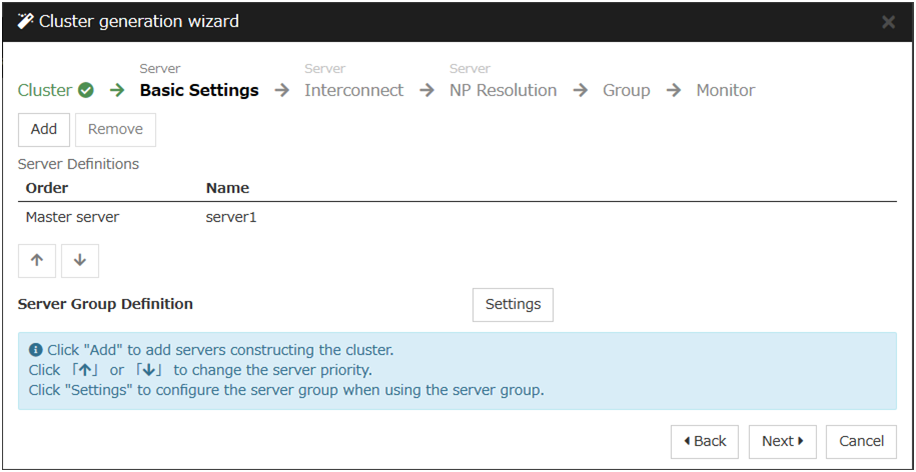
6.4.1.2. Add a server
Add the second and subsequent servers to the cluster.
In Server Definitions, click Add.
The Add Server dialog box is displayed. Enter the server name, FQDN name, or IP address of the second server, and then click OK. The second server (server2) is added to the Server Definitions.
For the hybrid disk configuration, add the third server (server3) in the same way.
For the hybrid disk configuration, follow the procedure in "1-3 Create a server group."
Click Next.
6.4.1.3. Create a server group
For the hybrid disk configuration, create a group of servers connected to the disk on each disk to be mirrored before creating a hybrid disk resource.
Click Settings in Server Group Definition.
Click Add in Server group.
The Server Group Definition dialog box is displayed. Enter the server group name svg1 in the Name box.
- Click server1 from Available Servers, and then, click Add. The server1 is added in Servers that can run the Group.Likewise, add server2.
Click OK. The svg1 is added in Server Group Definitions.
Click Add to open the Server Group Definition dialog box. Enter the server group name svg2 in the Name box.
Click server3 from Available Servers, and then, click Add. The server3 is added in Servers that can run the Group.
Click OK. The svg1 and svg2 are added in Server Group Definitions.

Click Close.
Click Next.
6.4.1.4. Set up the network configuration
Set up the network configuration between the servers in the cluster.

Add or delete them by using Add or Delete, click a cell in each server column, and then select or enter the IP address. For a communication route to which some servers are not connected, leave the cells for the unconnected servers blank.
- For a communication route used for heartbeat transmission (interconnect), click a cell in the Type column, and then select Kernel Mode. When using only for the data mirroring communication of the mirror disk resource or the hybrid disk resource and not using for the heartbeat, select Mirror Communication Only.At least one communication route must be specified for the interconnect. Specify as many communication routes for the interconnect as possible.If multiple interconnects are set up, the communication route for which the Priority column contains the smallest number is used preferentially for internal communication between the servers in the cluster. To change the priority, change the order of communication routes by selecting arrows.
When using BMC heartbeat, click a cell in the Type column, and then select BMC. Next, click a cell of each server, and then enter the BMC IP address. For servers that do not use BMC heartbeat, make the cells of those servers blank.
When using Witness heartbeat, click a cell in the Type column, and select Witness. Next, click Properties, and enter the address of Witness server for Target Host. Then enter the port number for Service Port. For servers that do not use Witness heartbeat, click the cells of those servers, and select Do Not Use.
For a communication route used for data mirroring communication for mirror disk resources or hybrid disk resources, click a cell of the MDC column, and then select the mirror disk connect name (mdc1 to mdc16) assigned to the communication route. Select Do Not Use for communication routes not used for data mirroring communication.
Click Next.
6.4.1.5. Set up network partition resolution
Set up the network partition resolution resource.

- To use NP resolution in the COM mode, click Add and add a row to NP Resolution List, click Type and select COM, and then, click the cell of each server and select the COM port of each server which is connected with a cross cable. If there are any servers that are not connected, make the cells of the servers to blank.For the setup example in this chapter, add COM mode row and select COM1 on the cell of each server to use the shared disk.
- To use NP resolution in the DISK mode, click Add and add a row to NP Resolution List, click Type and select DISK, and then, click the cell of each server and select the disk drive to be used for the partition for disk heartbeat. If there are any servers that are not connected to the shared disk, make the cells of the servers blank.For the setup example in this chapter, add a DISK mode row and click the column of each server, and then select the E: drive to use the shared disk. To use a hybrid disk, add a DISK mode column, click the cells of server1 and server2, and then select the E: drive. Make the server3 cell blank.
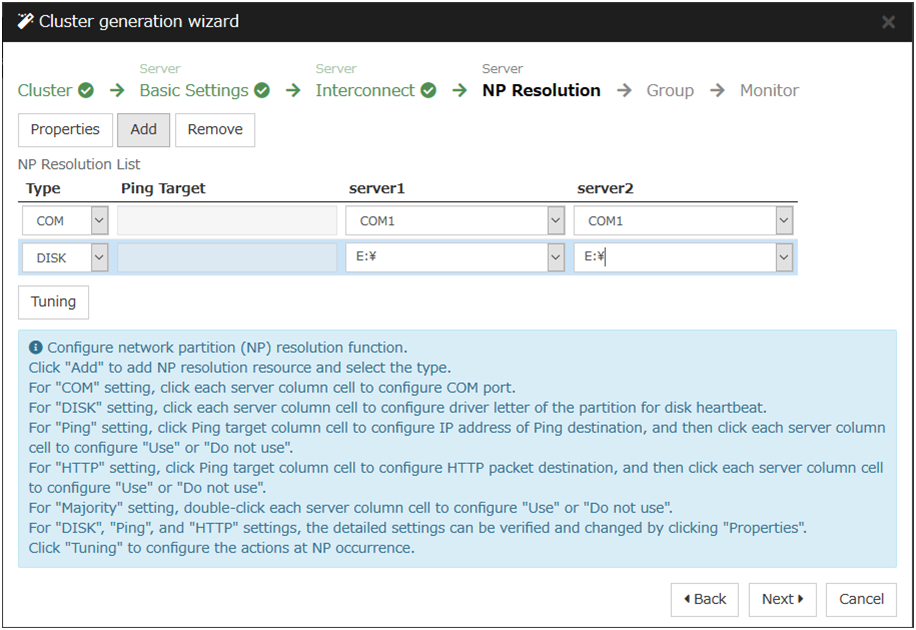
- To use NP resolution in the PING mode, click Add and add a row to NP Resolution List, click Type and select Ping, click the cell of Ping Target, and enter the IP addresses of the ping destination target devices (such as a gateway). When multiple IP addresses separated by commas are entered, they are regarded as isolated from the network if there is no ping response from any of them.If the PING mode is used only on some servers, set the cell of the server not to be used to Do Not Use.For the setup example in this chapter, a row for the PING mode is added and 192.168.0.254 is specified for Ping Target.

- To use NP resolution in the HTTP mode, add a row to NP Resolution List by clicking Add, click the cell in Type column, and select HTTP/HTTPS. Then click Properties, enter the address of the Web server in Target Host, and enter the port number in Service Port. If the HTTP mode is used only on some servers, set the cells of the servers not to be used to Do Not Use.For the setup example in this chapter, the HTTP mode is not used.
- To use the majority method for NP resolution, click Add and add a row to NP Resolution List, click the cell of Type column, and then select Majority.For the setup example in this chapter, the majority method is not used.
Click Next.
6.4.2. Create a failover group
Add a failover group that executes an application to the cluster. (Below, failover group is sometimes abbreviated to group.)
6.4.2.1. Add a failover group
Set up a group that works as a unit of failover at the time an error occurs.
- Click Add in the Group List to open the Group Definition dialog box.For the setup example in this chapter, select Use Server Group Settings checkbox to use a hybrid disk. Enter the group name (failover1) in the Name box, and click Next.
- Specify a server on which the failover group can start up. For the setup example in this chapter, to use the shared disk or the mirror disk, select the Failover is possible at all servers check box or add server1 and then server2 from the Available Servers and add them to the Servers that can run the Group. To use the hybrid disk, add svg1 and then svg2 from the Available Server Groups to the Server Groups that can run the Group

Click Next.
- Specify each attribute value of the failover group. Because all the default values are used for the setup example in this chapter, click Next.The Group Resource List is displayed.
6.4.2.2. Add a group resource (Floating IP resource)
Add a group resource, a configuration element of the group, to the failover group you have created in Step 2-1.
Click Add in the Group Resource List.
The Resource Definition of Group | failover1 dialog box is displayed. In the Resource Definition of Group(failover1) dialog box, select the group resource type Floating IP resource in the Type box, and enter the group resource name fip1 in the Name box. Click Next.
The Dependent Resources page is displayed. Specify nothing. Click Next.
The Recovery Operation at Activation Failure Detection and Recovery Operation at Deactivation Failure Detection pages are displayed. Click Next.
- Enter IP address (10.0.0.12) to IP Address box. Click Finish.The floating IP resource is added to Group Resource List.
6.4.2.3. Add a group resource (Disk resource/Mirror disk resource/Hybrid disk resource)
When using a shared disk
Add a shared disk as a group resource.
Click Add in Group Resource List.
The Resource Definition of Group | failover1 dialog box is displayed. In the Resource Definition of Group | failover1 dialog box, select the group resource type disk resource in the Type box, and enter the group resource name sd1 in the Name box. Click Next.
The Dependent Resources page is displayed. Specify nothing. Click Next.
The Recovery Operation at Activation Failure Detection and Recovery Operation at Deactivation Failure Detection pages are displayed. Click Next.
Select server1 in the Servers that can run the Group. Click Add.
The Selection of partition dialog box is displayed. Select the partition F:. Click OK.
Important
For disk resource partition, specify an unformatted partition on the shared disk that is connected to the filtering-configured HBA.
Make sure not to specify the disk resource partition to partition for disk heartbeat partition, or cluster partition or data partition for mirror disk resource. Data on the shared disk may be corrupted.
When using a mirror disk
Add a mirror disk as a group resource.
Click Add in Group Resource List.
The Resource Definition of Group | failover1 dialog box is displayed. In the Resource Definition of Group | failover1 dialog box, select the group resource type mirror disk resource in the Type box, and enter the group resource name md1 in the Name box. Click Next.
The Dependent Resources page is displayed. Specify nothing. Click Next.
The Recovery Operation at Activation Failure Detection and Recovery Operation at Deactivation Failure Detection pages are displayed. Click Next.
Select server1 in the Servers that can run the Group. Click Add.
The Selection of partition dialog box is displayed. In the Selection of Partition dialog box, click Connect, and then, select a data partition F: and cluster partition E:. Click OK.
Important
Specify different partitions for data partition and cluster partition. If the same partition is specified, data on the mirror disk may be corrupted. Make sure not to specify a partition on the shared disk for the data partition and cluster partition of mirror disk resource.
When using a hybrid disk
Add a hybrid disk as a group resource.
Click Add in Group Resource List.
The Resource Definition of Group | failover1 dialog box is displayed. In the Resource Definition of Group | failover1 dialog box, select the group resource type hybrid disk resource in the Type box, and enter the group resource name hd1 in the Name box. Click Next.
The Dependent Resources page is displayed. Specify nothing. Click Next.
The Recovery Operation at Activation Failure Detection and Recovery Operation at Deactivation Failure Detection pages are displayed. Click Next.
Enter the drive letter (G:) of the data partition for mirroring in the Data Partition Drive Letter box, the drive letter (F:) of the cluster partition in the Cluster Partition Drive Letter box.
Important
Specify different partitions for data partition and cluster partition. If the same partition is specified, data on the mirror disk may be corrupted.
6.4.2.4. Add a group resource (Application resource)
Add an application resource that can start and stop the application.
Click Add in Group Resource List.
The Resource Definition of Group | failover1 dialog box is displayed. In the Resource Definition of Group | failover1 dialog box, select the group resource type Application resource in the Type box, and enter the group resource name appli1 in the Name box. Click Next.
The Dependent Resources page is displayed. Specify nothing. Click Next.
The Recovery Operation at Activation Failure Detection and Recovery Operation at Deactivation Failure Detection pages are displayed. Click Next.
Select Resident in the Resident Type. Specify the path of the execution file for the Start Path.
Note
For the Start Path and Stop Path, specify an absolute path of the executable file or the name of the executable file of which the path configured with environment variable is effective. Do not specify a relative path. If it is specified, starting up the application resource may fail.
- Click Finish.The application resource is added to Group Resource List.

Click Finish.
6.4.3. Create monitor resources
Add a monitor resource that monitors a specified target to the cluster.
6.4.3.1. Add a monitor resource (Disk RW monitor resource)
Add RW monitor resource to monitor the local disk.
Click Next in Group List.
The Monitor Resource List is displayed. In the Monitor Resource List, click Add. Select the monitor resource type disk RW monitor in the Type box, and enter the monitor resource name diskw1 in the Name box. Click Next.
Enter the monitor settings. Select Always in the Monitor Timing box. Click Next.
Set the file name C:/check.txt and I/O size (2000000). Select Action on Stall (Generate an Intentional Stop Error) and Action When Diskfull Is Detected (Recover), and click Next. For File Name, specify the file of the partition where OS is installed.
Select Execute only the final action in the Recovery Action box.
- Select Generate an Intentional Stop Error in the Final Action box, and click Finish.The disk RW monitor resource diskw1 is added to the Monitor Resource List.
Note
By specifying a file in the local disk for the monitoring target of the disk RW monitoring resource, monitoring can be performed as the local disk monitoring. In such a case, select Generate an Intentional Stop Error for the Final Action.
6.4.3.2. Add a monitor resource (IP monitor resource)
Add monitor resources that monitor IP.
Click Add in the Monitor Resource List dialog box. Select the monitor resource type ip monitor in the Type box, and enter the monitor resource name ipw1 in the Name box. Click Next.
Enter the monitor settings. Change nothing from the default values. Click Next.
Click Add in the IP Addresses. Enter the IP address to be monitored 192.168.0.254 in the IP Address box, and click OK.
Note
For monitoring target of the IP monitor resource, specify the IP address of a device (for example, gateway) that is assumed to be always active on the public LAN.
The IP address you have entered is set in the IP Addresses. Click Next.
Specify the recovery target. Click Browse.
Click All Groups in the tree view and click OK. All Groups is set in the Recovery Target.
- Click Finish.The IP monitor resource ipw1 is added to the Monitor Resource List.
6.4.4. Disabling the cluster operation
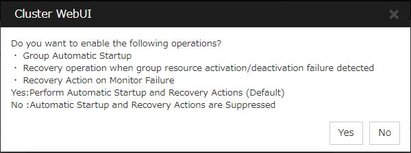
Clicking No disables automatic group startup, recovery on the activation/deactivation failure of a group resource, and recovery on the failure of a monitor resource. To start a cluster for the first time after creating the cluster configuration data, it is recommended to disable the automatic start and the recovery and to check the cluster configuration data for errors.
To disable the cluster operation, go to Cluster properties -> Extension tab -> Disable cluster operation.
Note
Even if the cluster operation is disabled, failover is performed upon a server failure.
Disabling the recovery on the failure of a monitor resource is not applied to the function of detecting the stall of the disk RW monitor resource.
Create cluster configuration information is complete. Proceed to the next section, "6.6. Starting a cluster".
6.5. Saving the cluster configuration data
The cluster configuration data can be saved in a file system or in media such as a floppy disk.
6.5.1. Saving the cluster configuration data
Follow the procedures below to save the cluster configuration.
Click Export in the config mode of Cluster WebUI.
Select a location to save the data and save it.
Note
One file (clp.conf) and one directory (scripts) are saved. If any of these are missing, the command to create a cluster does not run successfully. Make sure to treat these two as a set. When new configuration data is edited, clp.conf.bak is created in addition to these two.
Note
When installing EXPRESSCLUSTER, if the port number different from the default value is specified in Port Number, click Cluster Properties and click Port Number and specify the same values for WebManager HTTP Port Number and Disk Agent Port Number specified at the time of installation before saving the cluster configuration data.
6.6. Starting a cluster
After creating and/or modifying a cluster configuration data, apply the configuration data on the servers that constitute a cluster and create a cluster system.
6.6.1. How to create a cluster
After creation and modification of the cluster configuration data are completed, create a cluster in the following procedures.
- Click Apply the Configuration File in the config mode of Cluster WebUI.A popup message asking "Do you want to perform the operations?" is displayed. Click OK.When the upload ends successfully, a popup message saying "The application finished successfully." is displayed. Click OK.If the upload fails, perform the operations by following the displayed message.
Select the Operation Mode on the drop down menu of the toolbar in Cluster WebUI to switch to the operation mode.
- Select Start Cluster in the Status tab of Cluster WebUI and click.Confirm that a cluster system starts and the status of the cluster is displayed to the Cluster WebUI. If the cluster system does not start normally, take action according to an error message.
 For how to operate and check the Cluster WebUI, see the online manual from the
 button on the upper right of the screen.
Note
When installing EXPRESSCLUSTER, if the port number different from the default value is specified in Port Number, click Cluster Properties and click Port Number and specify the same values for WebManager HTTP Port Number and Disk Agent Port Number specified at the time of installation before saving the cluster configuration data.
7. Verifying a cluster system
7.1. Verifying the status using the Cluster WebUI
This chapter provides instructions for verifying the cluster system by using the Cluster WebUI. The Cluster WebUI is installed at the time of the EXPRESSCLUSTER Server installation. Therefore, it is not necessary to install it separately. The overview of the Cluster WebUI is provided. Then how to verify a cluster by accessing the Cluster WebUI is described.
See also
For system requirements of the Cluster WebUI, see the "Getting Started Guide".
Follow the steps below to verify the operation of the cluster after creating the cluster and connecting to the Cluster WebUI.
See also
For how to operate Cluster WebUI, see the online manual. If any error is detected while checking the status, troubleshoot the error referring to "Troubleshooting" in the "Reference Guide".
- Check heartbeat resourcesCheck on the Cluster WebUI that the each server has been rebooted and that the heartbeat resource status of each server is normal. Check that no alert or error is recorded in the alert view of the Cluster WebUI.
- Check monitor resourcesVerify that the status of each monitor resource is normal on the Cluster WebUI.
- Start up a groupStart a group.Check on the Cluster WebUI that the group has been started and that group resources included in the group have been started.Check that no alert or error is recorded in the alert view of the Cluster WebUI.
- Check a disk resource and mirror disk resources/hybrid disk resourceCheck that you can access the resource switching partition or data partition on the server where a disk resource/mirror disk resource/hybrid disk is active. Check that you cannot access the resource switching partition or data partition on the server where any resource described above is not active.
- Check a floating IP resourceCheck that you can ping a floating IP address while the floating IP is active.
- Check an application resourceCheck that an application is working on the server where an application resource is active.
- Check a service resourceCheck that a service is working on the server where a service resource is active.
- Stop a groupStop a group.Verify on the Cluster WebUI that the group has been stopped and that each group resource included in the group has been stopped. Verify that no alert or error is recorded in the alert view of the Cluster WebUI.
- Start a groupStart a group.Verify on the Cluster WebUI that the group has been started.
- Move a groupMove a group to another server.Check on the Cluster WebUI that the group has been started on the moving destination sever.Verify that each group resource has been started successfully and that no alert or error is recorded in the alert view of the Cluster WebUI.Move the group to all servers included in the failover policy to check above mentioned issue.
- Perform failoverShut down the server where a group is active.After the heartbeat timeout, check to see the group has failed over. Verify that the status of the group becomes activated on the failover destination server on the Cluster WebUI.
- Perform failbackWhen the automatic failback is set, start the server that you shut down for checking failover. Verify that the group fails back to the original server after it is started. Check on the Cluster WebUI that the status of group becomes activated on the failback destination server.
Note
For groups that include mirror disk resource or hybrid disk resource, auto failback cannot be set because mirror recovery is required.
- Check the alert optionWhen the alert option is set, check that an alert mail message is sent after checking a failover.
- Shut down the clusterShut down the cluster. Verify that all servers in the cluster are successfully shut down Also, check that all servers start successfully by restarting them. At the same time, check that no alert or error is recorded in the Alert logs of the Cluster WebUI.
7.2. Verifying status using commands
Follow the steps below to verify the status of the cluster from a server constituting the cluster using command lines after the cluster is created.
See also
For details on how to use commands, see "EXPRESSCLUSTER command reference" in the "Reference Guide". If any error is detected while verifying the status, troubleshoot the error referring to "Troubleshooting" in the "Reference Guide".
- Check heartbeat resourcesCheck that the status of each server is activated by using the clpstat command.Verify that the heartbeat resource status of each server is normal.
- Check monitor resourcesVerify that the status of each monitor resource is normal by using the clpstat command.
- Start groupsStart the groups with the clpgrp command.Verify that the status of groups is activated by using the clpstat command.
- Check a disk resource/mirror disk resource/hybrid disk resourceCheck that you can access the resource switching partition or data partition on the server where a disk resource/mirror disk resource/hybrid disk is active. Check that you cannot access the resource switching partition or data partition on the server where any resource described above is not active.
- Check a floating IP resourceVerify that you can ping a floating IP address while the IP resource is active.
- Check an application resourceVerify that an application is working on the server where the application resource is active.
- Check a service resourceVerify that a service is working on the server where the service resource is active.
- Stop a groupStop a group by using the clpgrp command. Check that the group is stopped by using the clpstat command.
- Start a groupStart a group by using the clpgrp command. Check that the group is activated by using the clpstat command.
- Move a groupMove a group to another server by using the clpstat command.Verify that the status of the group is activated by using the clpstat command.Move the group to all servers in the failover policy and verify that the status changes to activated on each server.
- Perform failoverShut down a server where a group is active.After the heartbeat timeout, check to see the group has failed over by using the clpstat command. Verify that the status of the group becomes activated on the failover destination server using the clpstat command.
- Perform failback (When it is set)When the automatic failback is set, start the server which you shut down in the previous step, "11. Perform failover." Verify that the group fails back to the original server after it is started using the clpstat command. Verify that the status of the group becomes activated on the failback destination server using the clpstat command.
- Check the alert option (When it is set)When the alert option is set, verify that a mail message is sent at failover.
- Shut down the clusterShut down the cluster by using the clpstdn command. Verify that all servers in the cluster are successfully shut down.
8. Verifying operation
This chapter provides information on how to run dummy-failure tests to see the behaviors of your cluster system and how to adjust parameters.
This chapter covers:
8.1. Operation tests
- Transition of recovery operations due to dummy failureWhen Dummy Failure is enabled, a test must be conducted to check that recovery of the monitor resources in which an error was detected is performed as set.You can perform this test from Cluster WebUI or with the clpmonctrl command. For details, see the online manual or "EXPRESSCLUSTER command reference" in the "Reference Guide".
- Dummy-failure of the shared disks(When the shared disk is RAID-configured and dummy-failure tests can be run)The test must include error, replacement, and recovery of RAID for the shared disk.
Set a dummy-failure to occur on the shared disk.
Recover RAID from the degenerated state to normal state.
For some shared disk, I/O may temporarily stop or delay when it switches to the degenerated operation or when the RAID is reconfigured.If any time-out and/or delay occurs in disk rw monitor resource or disk TUR monitor resource, adjust the time-out value of each monitor resource. - Dummy-failure of the paths to shared disks(When the path to the shared disk is redundant paths and dummy-failure tests can be run.)The test must include an error in the paths and switching of one path to another.
Set a dummy-failure to occur in the primary path.
It takes time for some path-switching software (driver) to switch the failed path to the path normally working. In some cases, the control may not be returned to the operating system (software).If any time-out and/or delay occurs in disk rw monitor resource or disk TUR monitor resource, adjust the time-out value of each monitor resource. - Backup/RestorationIf you plan to perform regular backups, run a test backup.Some backup software and archive commands make CPU and/or disk I/O highly loaded.If any heartbeat delays, delay in monitor resources, or time-out occur, adjust the heartbeat time-out value and/or time-out value of each monitor resource.
The following describes dummy-failures and what occur by the dummy-failures on a device basis. What occurs varies depending on a system configuration and resource settings. The table in the next page shows the operational examples in the general setting and configuration.
Device |
Dummy-failure |
What happens: |
|---|---|---|
Disk device SCSI/FC path |
Unplug the cable on the active server (for redundant disk cable, unplug both cables) |
When the shared disk is monitored, an error is detected, and failover to the standby server occurs. When no disk is monitored, the operation stops.
Deactivation of a disk resource may fail when performing failover.
|
Unplug the cable on the standby server (for redundancy, unplug both cables) |
When the disk TUR monitor resource monitors the disk path on the standby server, an error is detected. The operation continues on the active server. |
|
Unplug the cable of the primary path when the disk path is redundant. (When FC Switch is used, power it off as well.) |
Switching of the disk path is performed by the path switching software. No error is detected on the EXPRESSCLUSTER and the operation continues. |
|
In the state of one side path described above, restart the server by moving a group or shutting down the cluster. |
The disk path operates in the same way as it is normal. |
|
Degenerate and/or recover the RAID of the disk device. |
No error is detected on EXPRESSCLUSTER, and the operation continues. |
|
When the disk device controller is duplicated, stop the one side. |
When the path is duplicated, the disk path is switched by the path switching software. No error is detected on EXPRESSCLUSTER, and the operation continues.
When the path is not duplicated and each server is connected directly to the disk, an error is detected by the disk TUR monitor resource on the server connected to the stopped controller, failover to the standby server is performed. (When the controller on the standby server stops, the operation continues.)
|
|
Interconnect LAN |
Unplug the cable dedicated to LAN |
The LAN heartbeat resource on the interconnect becomes offline.
A warning is issued to the alert log.
Communication between servers continues by using a public LAN
= Operation continues.
|
Public LAN |
Unplug the LAN cable or power off the HUB |
Communication with the operational client stops, application stalls or an error occurs.
LAN heartbeat resource on the public LAN becomes inactive. A warning is issued to the alert log.
An error is detected when using IP monitor resource and/or NIC Link Up/Down monitor resource. When the cable on the active server is unplugged, a failover occurs. (When HUB is powered off, a failover is repeated up to the largest count configured.
When the public LAN is the only communication channel between servers (such as the remote cluster configuration), emergency shutdown due to the network partition resolving in the ping method takes place in the server where LAN cable is unplugged.
|
Server UPS |
Unplug the power cable of UPS on the active server from outlet |
The active server shuts down
Failover to the standby server occurs
|
UPS on a shared disk |
When the power of the shared disk is duplicated, unplug one of the power cables from outlet. |
No error is detected on EXPRESSCLUSTER and the operation continues. When UPS supplies the power to one server, the server shuts down. (If it is the active server, failover to the standby server takes place) |
LAN for UPS |
Unplug the LAN cable |
UPS becomes uncontrollable. However, no error is detected on EXPRESSCLUSTER and operation continues. |
COM |
Unplug the RS-232C cable of the COM network partition resolving. |
A warning is issued to the alert log.
Operation continues.
|
OS error |
Run the shutdown command on the active server |
The active server shuts down
Failover to a standby server occurs.
|
Mirror connect |
When more than one LAN cable is set up for the mirror connect and one or more of them are connected
Unplug only the LAN cable that is being used as the mirror connect.
|
Continue the mirroring operation |
When only one LAN cable is set up for the mirror connect, or when more than one LAN cable is set up for the mirror connect but none of them are connected
Unplug only the LAN cable that is being used as the mirror connect.
|
A warning is issued to the alert log (mirroring stops)
Operation continues on the active server but switching to a standby server becomes impossible.
An error is detected in mirror disk monitor resource/mirror connect disk resource/hybrid disk monitor resource.
|
|
Disk resource |
Start up the disk resource on the server where the disk path is unplugged. |
The disk resource does not get activated. |
Failover to a standby server occurs.
|
||
Application resource |
Start up the application resource on the server where the name of the file or folder configured for the start path of the application resource was temporarily changed. |
The application resource does not get activated.
Failover to a standby server occurs.
|
Application monitor resource |
Stop a process to be monitored by the task manager. |
An error is detected. The application is restarted or a failover to the standby server occurs. |
Service resource |
Start up the service resource on the server where the path or name of the service's execution file was temporarily changed. |
The service resource does not get activated.
Failover to a standby server occurs.
|
Service monitor resource |
Stop a service to be monitored. |
An error is detected. The service is restarted or a |
failover to a standby server occurs. |
||
Floating IP address |
Specify the IP address that was set to a floating IP address to a machine in the same segment, and then start up the floating IP address resource. |
The floating IP resource does not get activated.
Failover to a standby server occurs. (Activation fails at the failover destination. Failover is repeated up to the largest count configured)
|
VM resource |
Disconnect the shared disk containing the virtual machine image. |
The VM resource is not activated. |
VM monitor resource |
Shut down the virtual machine. |
The virtual machine is started by restarting the resource. |
See also
For information on how to change each parameter, see the "Reference Guide".
8.2. Backup and restoration
The following figure illustrates backup and restoration of data. For details on how to back up, see "The system maintenance information" in the "Maintenance Guide" and manuals backup software.
The following is an example of the backup on the uni-directional standby server.
Data in a shared disk and in a local disk is backed up to a backup device connected to the active server (Server 1).
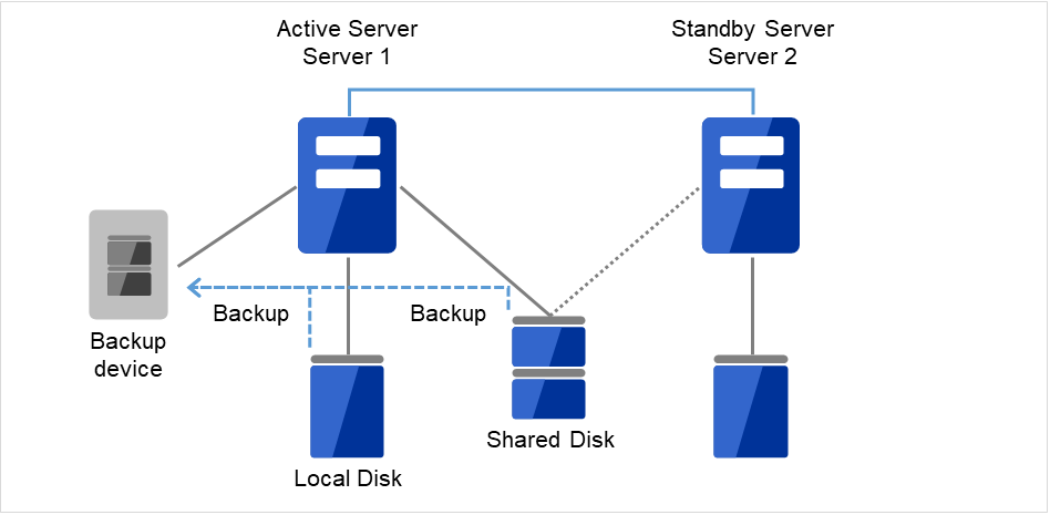
Fig. 8.1 Example of data backup in a uni-directional standby cluster (1)
When an error occurs in Server 1, the data in the shared disk and in the local disk is backed up to a backup device connected to the standby server (Server 2).
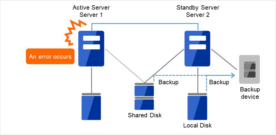
Fig. 8.2 Example of data backup in a uni-directional standby cluster (2)
9. Preparing to operate a cluster system
9.1. Operating the cluster
Before you start using your cluster system, check to see your cluster system work properly and make sure you can use the system properly. The operations described below can be executed by using Cluster WebUI or EXPRESSCLUSTER commands. For details of functions of Cluster WebUI, see the online manual. For the details of EXPRESSCLUSTER commands, see "EXPRESSCLUSTER command reference " in the "Reference Guide".The following describes procedures to start up and shut down a cluster and to shut down a server.
9.1.1. Activating a cluster
To activate a cluster, follow the instructions below:
When you are using any shared or add-in disk, start the disk.
Start all the servers in the cluster.
After cluster activation synchronization between the servers has been confirmed, a cluster is activated on each server. After the cluster has been activated, a group is activated on an appropriate server according to the settings.
Note
When you start all the servers in the cluster, make sure they are started within the duration of time set to Server Sync Wait Time on the Timeout tab of the Cluster Properties in the Cluster WebUI. Be careful that failover occurs if startup of any server fails to be confirmed within the specified time duration.
Note
The shared disk spends a few minutes for initialization after its startup. If a server starts up during the initialization, the shared disk cannot be recognized. Make sure to set servers to start up after the shared disk initialization is completed.
9.1.2. Shutting down a cluster and server
To shut down a cluster or server, use EXPRESSCLUSTER commands or shut down through the Cluster WebUI.
Note
When you are using the Replicator/Replicator DR, mirror break may occur if you do not use any EXPRESSCLUSTER commands or Cluster WebUI to shut down a cluster.
9.1.3. Shutting down the entire cluster
The entire cluster can be shut down by running the clpstdn command, executing cluster shutdown from the Cluster WebUI or performing cluster shutdown from the Start menu. To shut down the entire cluster, wait for all the groups to stop and then terminate each server. By shutting down a cluster, all servers in the cluster can be stopped properly as a cluster system.
9.1.4. Shutting down a server
Shut down a server by running the clpdown command or executing server shutdown from the Cluster WebUI. Failover occurs when you shut down a server. Mirroring performed by mirror disk resources/hybrid disk resources is interrupted when you are using the Replicator/Replicator DR. If you intend to use a standby server while performing hardware maintenance, shut down the active server.
9.1.5. Suspending/resuming a cluster
When a cluster is suspended, some functions are disabled as described below because the EXPRESSCLUSTER service stops while the active resources are kept active.
All heartbeat resources stop.
All network partition resolution resources stop.
All monitor resources stop.
Groups or group resources are disabled (cannot be started, stopped, or moved).
The following commands cannot be used:
clpcl command options other than --resume
clpdown
clpstdn
clpgrp
clptoratio
clpmonctrl
clprsc
clpcpufreq
9.1.6. How to suspend a cluster
You can suspend a cluster by executing the clpcl command or by using Cluster WebUI.
9.1.7. How to resume a cluster
You can resume a cluster by executing the clpcl command or by using Cluster WebUI.
9.2. Suspending EXPRESSCLUSTER
There are two ways to stop running EXPRESSCLUSTER. One is to stop the service of the EXPRESSCLUSTER Server, and the other is to set the Server service to be manually started.
9.2.1. Stopping the EXPRESSCLUSTER Server service
To stop only the EXPRESSCLUSTER Server service without shutting down the operating system, use the clpcl command or Stop cluster from the Cluster WebUI.
See also
For more information on the clpcl command, see "EXPRESSCLUSTER command reference" in the "Reference Guide".
9.2.2. Setting the EXPRESSCLUSTER Server service to be manually activated
To make the EXPRESSCLUSTER Server service not start when the OS starts, make the setting by using the OS service manager so that the Server service is manually started. By doing this, the EXPRESSCLUSTER will not start when the OS is rebooted next time.
9.2.3. Changing the setting of the EXPRESSCLUSTER Server service from the manual startup to automatic startup
The OS service manager is also used to set the EXPRESSCLUSTER Server service to be started automatically. Even you change the settings, the EXPRESSCLUSTER Server service remains stopped until it is directly started up or the server is restarted.
9.3. Modifying the cluster configuration data
The following describes procedures and precautions for modifying the configuration data after creating a cluster.
9.3.1. Modifying the cluster configuration data by using the Cluster WebUI
Start the Cluster WebUI.
Select the Config Mode icon from the drop down menu of the tool bar in Cluster WebUI.
Modify the configuration data after the current cluster configuration data is displayed.
Upload the modified configuration data. Depending on the data modified, it may become necessary to suspend or stop the cluster and/or to restart by shutting down the cluster. In such a case, uploading is canceled once and the required operation is displayed. Follow the displayed message and do as instructed to perform upload again.
9.3.2. Applying the modified cluster configuration data
To upload the modified cluster configuration data by the Cluster WebUI or the clpcfctrl command, select the operation from the following depending on the modification. For the operation required to apply the modified data, refer to "Parameter details"in the "Reference Guide".
The way you apply the changed data may affect the applications on the system and the behavior of the EXPRESSCLUSTER Server. For details, see the table below:
# |
The way to apply changes |
Effect |
|---|---|---|
1 |
Upload only |
The operation of the EXPRESSCLUSTER Server is not affected. Heartbeat resources, group resources and monitor resource do not stop. |
2 |
Upload data and then restart the API service |
The operation of the EXPRESSCLUSTER Server is not affected. Heartbeat resources, group resources and monitor resource do not stop. |
3 |
Restart the WebManager server after uploading |
The operation of the EXPRESSCLUSTER Server is not affected. Heartbeat resources, group resources and monitor resource do not stop. |
4 |
Upload data and then restart the Information Base service |
The operation of the EXPRESSCLUSTER Server is not affected. Heartbeat resources, group resources and monitor resource do not stop. |
5 |
Upload after stopping the group whose setting has been changed |
Group resources are stopped. Because of this, the applications on the system that are controlled by the group are stopped until the group is started after uploading. |
6 |
Upload after suspending the cluster |
The EXPRESSCLUSTER is partly stopped.
During the period when the EXPRESSCLUSTER Server service is suspended, heartbeat resources and monitor resources are stopped. Because group resources do not stop, the applications on the system continue to operate.
|
7 |
Upload after stopping the cluster |
The EXPRESSCLUSTER totally stops. Groups stop as well. Therefore, the applications used on the system are stopped until data is uploaded and the cluster is started. |
8 |
Shut down and restart the cluster after uploading the data |
The applications used on the system are stopped until the cluster restarts and the group is started. |
Note
10. Uninstalling and reinstalling EXPRESSCLUSTER
10.1. Uninstallation
10.1.1. Uninstalling the EXPRESSCLUSTER Server
Note
You must log on as Administrator when uninstalling the EXPRESSCLUSTER Server. It is recommended to extract configuration information before performing uninstallation. For details, refer to "EXPRESSCLUSTER command reference" in the "Reference Guide".
Follow the procedures below to uninstall the EXPRESSCLUSTER Server:
Switch the type of service startup to manual startup.
clpsvcctrl.bat --disable -a
Shutdown the server.
If the shared disk is used, please unplug all disk cables connected to the server because disk filtering will be disabled after uninstallation.
Turn on the server.
In Control Panel in OS, click Programs and Features.
Select EXPRESSCLUSTER Server, and then click Uninstall.
The EXPRESSCLUSTER Server Setup dialog box is displayed.
Click Yes in the uninstallation confirmation dialog box. If you click No, uninstallation will be canceled.
- If the SNMP service is started, the message to confirm to stop the SNMP service is displayed. Click Yes. If you click No, uninstallation will be canceled.

- The message asking whether to return the media sense function (TCP/IP disconnection detection) to the state before installing the EXPRESSCLUSTER Server is displayed. Click Yes to return to the state before installing the EXPRESSCLUSTER Server. If you click No, EXPRESSCLUSTER will be uninstalled while media sense function is not effective.

The completion message is displayed when uninstallation is completed in the EXPRESSCLUSTER Server Setup dialog box. Click Finish.
The confirmation message whether to restart the computer is displayed. Select whether to restart the PC and click Finish. Uninstallation of the EXPRESSCLUSTER Server is completed.
Important
If the shared disk is used, make sure not to start the OS while the shared disk is connected after uninstalling EXPRESSCLUSTER. Data on the shared disk may be corrupted.
Note
If you uninstall EXPRESSCLUSTER with CPU frequency changed by using CPU Frequency Control of EXPRESSCLUSTER, the CPU frequency does not return to the state before changing. In this case, return the CPU frequency to the defined value by the following way.
Select Balanced in Power Options -> Choose or customize a power plan in Control Panel.
10.2. Reinstallation
10.2.1. Reinstalling the EXPRESSCLUSTER Server
To reinstall the EXPRESSCLUSTER Server, you have to prepare the cluster configuration data (or the latest data if you reconfigured the cluster) created by the Cluster WebUI.
After changing the configuration data, make sure to save the latest cluster configuration data. The configuration data backup can be created by the clpcfctrl command as well as it can be saved in the Cluster WebUI when being created. For details, refer to "Creating a cluster and backing up configuration data (clpcfctrl command)" in "EXPRESSCLUSTER command reference" in the "Reference Guide".
To reinstall EXPRESSCLUSTER Server on the entire cluster
To reinstall the EXPRESSCLUSTER Server, follow the procedures below:
Unplug disk all cables connected to all servers because access restriction does not function until reinstallation of the EXPRESSCLUSTER Server is completed.
Shut down OS after uninstalling the EXPRESSCLUSTER Server is completed.
Important
When a shared disk is used, make sure not to start the server connected to the shared disk while EXPRESSCLUSTER is uninstalled. Data on the shared disk may be corrupted.
Important
When a shared disk is used, make sure not to connect the shared disk to HBA without filtering settings or SCSI controller. Data on the shared disk may be corrupted.
To reinstall EXPRESSCLUSTER Server on some servers in the cluster
To reinstall the EXPRESSCLUSTER Server, follow the procedures below:
When a shared disk is used, unplug all disk cables connected to the servers on which you want to reinstall the EXPRESSCLUSTER Server. This is because the access control does not work until the reinstallation is completed.
Shut down the OS when uninstalling the EXPRESSCLUSTER Server is completed.
Important
When a shared disk is used, make sure not to start the server connected to the shared disk while EXPRESSCLUSTER is uninstalled. Data on the shared disk may be corrupted.
Important
When a shared disk is used, make sure not to connect the shared disk to HBA without filtering settings or SCSI controller. Data on the shared disk may be corrupted.
Connect to the Cluster WebUI in other servers in a cluster and switch to the Config mode.
If a shared disk is used and the OS is reinstalled, or if you modify HBA to connect the shared disk, update the filtering information in HBA tab in Server Properties of the server where the OS is reinstalled.
Important
To configure the filtering settings, click Server Properties of the server where the EXPRESSCLUSTER Server is installed, click HBA tab, and then click Connect. If the filtering setting is configured without clicking Connect, data on the shared disk may be corrupted.
From the server where the web browser of the Cluster WebUI is connected, run clpcl --suspend --force from the command prompt and suspend the cluster.
Apply the changes by the Config mode.
If the fixed-term license is used, run the following command.
clplcnsc --reregister <a folder path for saved license files>The following message is displayed if the changes has successfully been applied.
The application finished successfully.
Change the Cluster WebUI to Operation mode and resume the cluster from the Service menu.
Note
When resuming the cluster from the Cluster WebUI, the message "Failed to resume the cluster. Click the Reload button, or try again later." is displayed, but ignore this message.
Select Start Server Service for the server where EXPRESSCLUSTER Server is reinstalled from Cluster WebUI.
When Off is selected in Auto Return in Cluster Properties, click the server where the EXPRESSCLUSTER Server is reinstalled by using the Cluster WebUI and select Recover.
If necessary, move the group.
11. Troubleshooting
11.1. Error messages when installing the EXPRESSCLUSTER Server
Behavior and Message |
Cause |
Action |
|---|---|---|
failed to set up
Error code: %x
%x: error code
|
Refer to the given error code. |
Refer to the action for the error code. |
Less than 9.0 has been installed. After uninstalling, reinstall it again. |
The old version of the EXPRESSCLUSTER has been installed. |
Uninstall the old version of the EXPRESSCLUSTER and install the current version. |
Failed to set up (%d)
Error code: %x
After restart, install it.
%d: internal code
%x: error code
|
Refer to the explanation of the given error code. |
Refer to the action for the given error code. |
11.2. Licensing
Behavior and Message |
Cause |
Action |
|---|---|---|
When the cluster was shut down and rebooted after distribution of the configuration data created by the Cluster WebUI to all servers, the following message was displayed on the alert log, and the cluster stopped.
"The license is not registered. (Product name: %1)"
%1: Product name
|
The cluster has been shut down and rebooted without its license being registered. |
Register the license according to "Registering the license". |
When the cluster was shut down and rebooted after distribution of the configuration data created by the Cluster WebUI to all servers, the following message appeared on the alert log, but the cluster is working properly.
"The number of licenses is insufficient. The number of insufficient licenses is %1. (Product name:%2)"
%1: The number of licenses in short of supply
%2: Product name
|
Not enough license |
Obtain a license and register it. |
While the cluster was operated on the trial license, the following message is displayed and the cluster stopped.
"The trial license has expired in %1. (Product name: %2)"
%1: Trial end date
%2: Product name
|
The license has already expired. |
Ask your sales agent for extension of the trial version license, or obtain and register the product version license. |
While the cluster was operated on the fixed term license, the cluster operation was disabled with the following message outputted:
"The fixed term license has expired in %1. (Product name:%2)"
%1: Fixed term end day
%2: Product name
"Cluster operation is forcibly disabled since a valid license has not been registered."
|
The license has already expired. |
Obtain the license for the product version from the vendor, and then register the license. |
12. Glossary
- Active server
- A server that is running for an application set.(Related term: Standby server)
- Cluster partition
- A partition on a mirror disk. Used for managing mirror disks.(Related term: Disk heartbeat partition)
- Cluster shutdown
To shut down an entire cluster system (all servers that configure a cluster system).
- Cluster system
Multiple computers are connected via a LAN (or other network) and behave as if it were a single system.
- Data partition
- A local disk that can be used as a shared disk for switchable partition. Data partition for mirror disks.(Related term: Cluster partition)
- Disk heartbeat partition
A partition used for heartbeat communication in a shared disk type cluster.
- Failback
A process of returning an application back to an active server after an application fails over to another server.
- Failover
The process of a standby server taking over the group of resources that the active server previously was handling due to error detection.
- Failover group
A group of cluster resources and attributes required to execute an application.
- Failover policy
A priority list of servers that a group can fail over to.
- Floating IP address
- Clients can transparently switch one server from another when a failover occurs.Any unassigned IP address that has the same network address that a cluster server belongs to can be used as a floating address.
- Heartbeat
- Signals that servers in a cluster send to each other to detect a failure in a cluster.(Related terms: Interconnect, Network partition)
- Interconnect
- A dedicated communication path for server-to-server communication in a cluster.(Related terms: Private LAN, Public LAN)
- Management client
Any machine that uses the Cluster WebUI to access and manage a cluster system.
- Master server
The server displayed at the top of Master Server in Server Common Properties of the config mode of Cluster WebUI
- Mirror connect
LAN used for data mirroring in a data mirror type cluster. Mirror connect can be used with primary interconnect.
- Mirror disk type cluster
A cluster system that does not use a shared disk. Local disks of the servers are mirrored.
- Moving failover group
Moving an application from an active server to a standby server by a user.
- Network partition
- All heartbeat is lost and the network between servers is partitioned.(Related terms: Interconnect, Heartbeat)
- Node
A server that is part of a cluster in a cluster system. In networking terminology, it refers to devices, including computers and routers, that can transmit, receive, or process signals.
- Primary (server)
- A server that is the main server for a failover group.(Related term: Secondary server)
- Private LAN
- LAN in which only servers configured in a clustered system are connected.(Related terms: Interconnect, Public LAN)
- Public LAN
- A communication channel between clients and servers.(Related terms: Interconnect, Private LAN)
- Secondary server
- A destination server where a failover group fails over to during normal operations.(Related term: Primary server)
- Server Group
A group of servers connected to the same network or the shared disk device
A disk that multiple servers can access.
A cluster system that uses one or more shared disks.
- Standby server
- A server that is not an active server.(Related term: Active server)
- Startup attribute
A failover group attribute that determines whether a failover group should be started up automatically or manually when a cluster is started.
- Switchable partition
- A disk partition connected to multiple computers and is switchable among computers.(Related terms: Disk heartbeat partition)
- Virtual IP address
IP address used to configure a remote cluster.