1. Preface
1.1. Who Should Use This Guide
The HA Cluster Configuration Guide for Microsoft Azure (Linux) is intended for administrators who want to build a cluster system, and for system engineers and maintenance personnel who provide user support.
The software and setup examples introduced in this guide are for reference only, and the software is not guaranteed to run.
1.2. Scope of application
This guide covers the following product versions.
EXPRESSCLUSTER X 4.2 for Linux (Internal version: 4.2.0-1)
CentOS 7.6
Microsoft Azure portal: Environment as of December 19, 2019
Azure CLI 2.0
1.3. How This Guide is Organized
3. Operating Environments: Describes the tested operating environment of this function.
4. Cluster Creation Procedure (for an HA Cluster Using Azure DNS): Describes the procedure to create an HA cluster using Azure DNS.
5. Cluster Creation Procedure (for an HA Cluster Using an Public Load Balancer): Describes the procedure to create an HA cluster using an public load balancer.
6. Cluster Creation Procedure (for an HA Cluster Using an Internal Load Balancer): Describes the procedure to create an HA cluster using an internal load balancer.
7. Error Messages: Describes the error messages and solutions.
8. Notes and Restrictions: Describes the notes and restrictions on creating and operating a cluster.
1.4. EXPRESSCLUSTER X Documentation Set
The EXPRESSCLUSTER X manuals consist of the following six guides. The title and purpose of each guide is described below:
EXPRESSCLUSTER X Getting Started Guide
This guide is intended for all users. The guide covers topics such as product overview, system requirements, and known problems.
EXPRESSCLUSTER X Installation and Configuration Guide
This guide is intended for system engineers and administrators who want to build, operate, and maintain a cluster system. Instructions for designing, installing, and configuring a cluster system with EXPRESSCLUSTER are covered in this guide.
EXPRESSCLUSTER X Reference Guide
This guide is intended for system administrators. The guide covers topics such as how to operate EXPRESSCLUSTER, function of each module and troubleshooting. The guide is supplement to the Installation and Configuration Guide.
EXPRESSCLUSTER X Maintenance Guide
This guide is intended for administrators and for system administrators who want to build, operate, and maintain EXPRESSCLUSTER-based cluster systems. The guide describes maintenance-related topics for EXPRESSCLUSTER.
EXPRESSCLUSTER X Hardware Feature Guide
This guide is intended for administrators and for system engineers who want to build EXPRESSCLUSTER-based cluster systems. The guide describes features to work with specific hardware, serving as a supplement to the Installation and Configuration Guide.
EXPRESSCLUSTER X Legacy Feature Guide
This guide is intended for administrators and for system engineers who want to build EXPRESSCLUSTER-based cluster systems. The guide describes EXPRESSCLUSTER X 4.0 WebManager and Builder.
1.5. Conventions
In this guide, Note, Important, See also are used as follows:
Note
Used when the information given is important, but not related to the data loss and damage to the system and machine.
Important
Used when the information given is necessary to avoid the data loss and damage to the system and machine.
See also
Used to describe the location of the information given at the reference destination.
The following conventions are used in this guide.
Convention |
Usage |
Example |
|---|---|---|
Bold |
Indicates graphical objects, such as text boxes, list boxes, menu selections, buttons, labels, icons, etc. |
Click Start.
Properties dialog box
|
Angled bracket within the command line |
Indicates that the value specified inside of the angled bracket can be omitted. |
|
# |
Prompt to indicate that a Linux user has logged on as root user. |
|
Monospace (Courier) |
Indicates path names, commands, system output (message, prompt, etc.), directory, file names, functions and parameters. |
/Linux |
Monospace bold (Courier) |
Indicates the value that a user actually enters from a command line. |
Enter the following:
# clpcl -s -a |
Monospace italic (Courier) |
Indicates that users should replace italicized part with values that they are actually working with. |
|
1.6. Contacting NEC
For the latest product information, visit our website below:
2. Overview
2.1. Functional overview
This guide describes how to configure an HA cluster based on EXPRESSCLUSTER X (hereinafter referred to as "EXPRESSCLUSTER") using Azure Resource Manager on a Microsoft Azure cloud service.
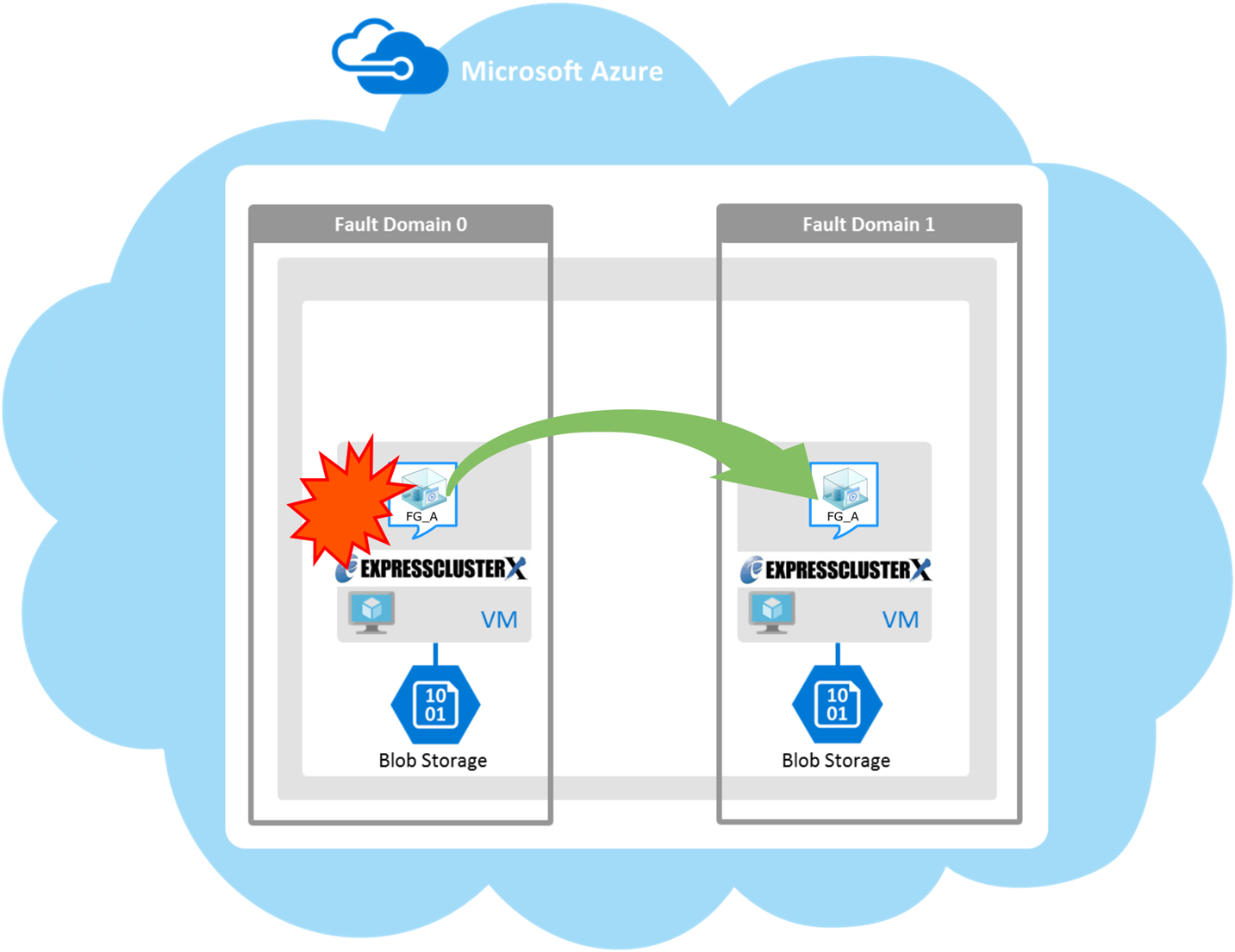
Fig. 2.1 HA Cluster on a Cloud Service (Using Azure DNS)
Operational availability can be increased by clustering virtual machines (VMs in Figure 2.1 HA Cluster on a Cloud Service (Using Azure DNS)) using a Microsoft Azure region and availability set in a Microsoft Azure environment.
Microsoft Azure region
Physical and logical units called a Microsoft Azure region are provided.It is possible to build all nodes in a single region (such as Japan East or Japan West). However, if all nodes are built in a single region, there is a possibility for nodes to go down due to a network failure or natural disaster, causing interruption to the flow of business. Distributing nodes into multiple regions can improve the operational availability.Availability set
Microsoft Azure allows each node to be deployed in a logical group called an availability set. Locating each node in an availability set minimizes the impact of planned maintenance or unplanned maintenance due to a physical hardware failure of the Microsoft Azure platform. This guide describes the configuration using an availability set.For details about an availability set, see the following website:Manage the availability of Linux virtual machines:
2.2. Basic configuration
This guide assumes two types of HA clusters. One is an HA cluster using Azure DNS of the Resource Manager deployment model. The other is an HA cluster using a load balancer of the Resource Manager deployment model. (Both HA clusters are configured as a unidirectional standby cluster.) The following table describes the EXPRESSCLUSTER resources to be selected depending on the Microsoft Azure deployment model in use.
Purpose |
EXPRESSCLUSTER resource to use |
Accessing the cluster by using a DNS name
(Azure DNS needs to be installed)
|
Azure DNS resource |
Accessing the cluster by using a virtual IP address(global IP address)
(Use public load balancer)
|
Azure probe port resource |
Accessing the cluster by using a virtual IP address(private IP address)
(Use internal load balancer)
|
Azure probe port resource |
HA cluster using Azure DNS
In this configuration, two virtual machines are deployed the same resource group so that the cluster can be accessed by using the same DNS name. The EXPRESSCLUSER Azure DNS resource uses Azure DNS to enable access with a DNS name. For details about Azure DNS, see the following website:
Azure DNS: https://azure.microsoft.com/en-us/services/dns/

Fig. 2.2 HA Cluster Using Azure DNS
These two virtual machines use the same availability set to minimize the impact of planned maintenance or unplanned maintenance due to a physical hardware failure of the Microsoft Azure platform.
The cluster in Figure 2.2 HA Cluster Using Azure DNS is accessed by using the DNS name of the Azure DNS zone. EXPRESSCLUSTER manages record sets and DNS A records of the Azure DNS zone to find an IP address according to the DNS name. A client need not be conscious about the switching of virtual machines upon failover occurrence or group migration.
The following table describes the EXPRESSCLUSTER resources and monitor resources required for a HA cluster configuration using Azure DNS.
Resource or monitor resource type
Description
Setting
Azure DNS resource
Manages the record sets (A records) of the Azure DNS zone to find an IP address according to the DNS name.
Required
Azure DNS monitor resource
Monitors that the results of name resolution are normal in relation to the Azure DNS record set.
Required
IP monitor resource
Monitors whether communication with the Microsoft Azure Service Management API is possible, and also monitors health of communication with an external network.
When an public load balancer is used, required to monitor communication between clusters that are configured with virtual machines, and also to monitor health of communication with an internal network.
Custom monitor resource
Monitors communication between clusters that are configured with virtual machines, and also monitors health of communication with an internal network.
When an public load balancer is used, required to monitor whether communication with the Microsoft Azure Service Management API is possible, and also to monitor health of communication with an external network.
Multi target monitor resource
Monitors the statuses of both the IP monitor resource and custom monitor resource. If the statuses of both monitor resources are abnormal, a script in which a process for network partition resolution (NP resolution) is described is executed.
When an public load balancer is used, required to monitor health of communication between an internal network and external network.
Other resources and monitor resources
Depends on the configuration of application, such as a mirror disk, that is used in an HA cluster.
Optional
HA cluster using a load balancer

Fig. 2.3 HA Cluster Using an Public Load Balancer
A client application can connect a virtual machine on an availability set in a Microsoft Azure environment to a cluster node by using frontend IP address. By using a VIP (Virtual IP), a client need not be conscious about the switching of virtual machines upon failover occurrence or group migration.A cluster built in a Microsoft Azure environment in Figure 2.3 HA Cluster Using an Public Load Balancer is accessed by specifying a global IP address of the Microsoft Azure Load Balancer (Load Balancer in Figure 2.3 HA Cluster Using an Public Load Balancer).Active and standby nodes of a cluster are switched by using probes of Microsoft Azure Load Balancer. To use Microsoft Azure Load Balancer probes, use a probe port provided by the EXPRESSCLUSTER Azure probe port resource.Activating the Azure probe port resource starts a probe port control process in standby for alive monitoring (access to a probe port) from Microsoft Azure Load Balancer.Deactivating the Azure probe port resource stops a probe port control process in standby for alive monitoring (access to a probe port) from Microsoft Azure Load Balancer.The Azure probe port resource also supports the Microsoft Azure internal load balancer (Internal Load Balancing: ILB). For the internal load balancer, a Microsoft Azure private IP address is used as a VIP.
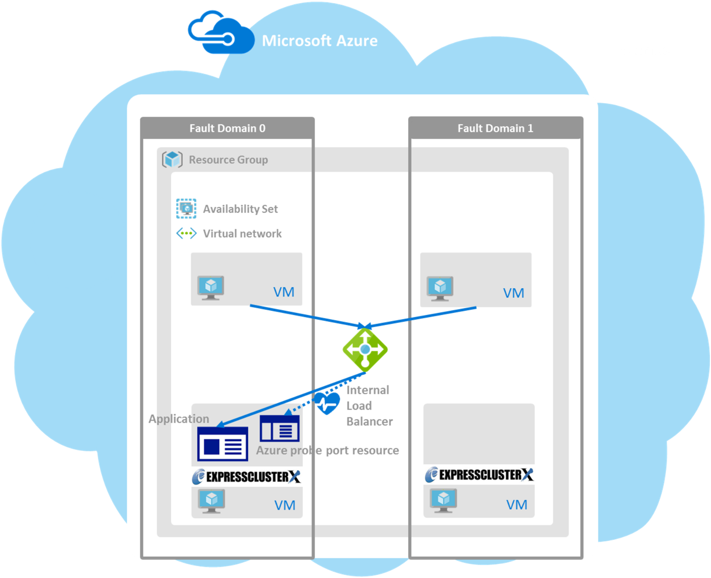
Fig. 2.4 HA Cluster Using the Internal Load Balancer
The following are examples of two HA cluster configurations using a load balancer. Select a load balancer to use depending on your purpose.
Purpose
Load balancer to use
Creating procedure
Disclosing operations outside the Microsoft Azure network
Public load balancer
See "5. Cluster Creation Procedure (for an HA Cluster Using an Public Load Balancer)" in this guide.
Publishing operations within the Microsoft Azure network
Internal load balancer (ILB)
See "6. Cluster Creation Procedure (for an HA Cluster Using an Internal Load Balancer)" in this guide.
The following table describes the EXPRESSCLUSTER resources and monitor resources required for a HA cluster using a load balancer.
Resource or monitor resource type
Description
Setting
Azure probe port resource
Provides a mechanism to wait for alive monitoring from a load balancer on a specific port of a node in which operations are running.
Required
Azure probe port monitor resource
Performs alive monitoring of a probe port control process, which starts upon activation of the Azure probe port resource, for a node in which the Azure probe port resource is running.
Required
Azure load balance monitor resource
Monitors whether a port with the same number as a probe port is open for a node in which the Azure probe port resource is not running.
Required
IP monitor resource
Monitors whether communication with the Microsoft Azure Service Management API is possible, and also monitors health of communication with an external network.
When an public load balancer is used, required to monitor communication between clusters that are configured with virtual machines, and also to monitor health of communication with an external network.
Custom monitor resource
Monitors communication between clusters that are configured with virtual machines, and also monitors health of communication with an internal network.
When an public load balancer is used, required to monitor whether communication with the Microsoft Azure Service Management API is possible, and also to monitor health of communication with an external network.
Multi target monitor resource
Monitors the statuses of both the IP monitor resource and custom monitor resource. If the statuses of both monitor resources are abnormal, a script in which a process for network partition resolution (NP resolution) is described is executed.
When anpublic load balancer is used, required to monitor health of communication between an internal network and external network.
PING network partition resolution resource
When an internal load balancer (ILB) is used, monitors health of communication between subnets by checking whether to communicate with a device that is always on and can return a response to ping (ping device).
When an internal load balancer (ILB) is used, required to monitor health of communication between subnets.
Other resources and monitor resources
Depends on the configuration of application, such as a mirror disk, that is used in an HA cluster.
Optional
2.3. Network partition resolution
Virtual machines configuring an HA cluster mutually performs alive monitoring through a heartbeat communication. If the virtual machines exist in different subnets, an undesirable event, such as an application starting more than once, occurs if a heartbeat ceases. To prevent a service from starting more than once, it is necessary to identify whether other virtual machines went down or whether the applicable virtual machine was isolated from a network (network partitioning: NP).
The network partition resolution feature (NP resolution) sends ping to or checks a LISTEN port of a device that is always on and can return a response to ping etc. (access destination). If there is no reply, this feature judges that the device entered the NP status and executes the specified action (such as a warning, recovery action, and server shutdown).
The access destination in the following table are used as ping devices for Microsoft Azure.(*) A private IP address of an internal load balancer (ILB) cannot be used because it does not reply to ping.
Scope of disclosure
access destination
Procedure
EXPRESSCLUSTER resources, monitor resources, and commands to be used for NP resolution
Outside the Microsoft Azure Virtual network
Microsoft Azure Service Management API (management.core.windows.net)
Checking a LISTEN port
each cluster server
Ping
IP monitor resource
Inside the Microsoft Azure Virtual network
Servers, excluding a cluster server, that exist within the Microsoft Azure network(*)
Ping
PING network partition resolution resource
Web servers that exist within the Microsoft Azure network
HTTP
HTTP network partition resolution resource
For details about NP resolution, see the following:
Setting the NP resolution destination
You need to examine the NP resolution destination and method depending on the location of clients accessing a cluster system and the condition for connecting to an on-premise environment (for example, using a dedicated line). There is no NP resolution destination nor method to recommend.
How to judge the network partition status
EXPRESSCLUSTER provides the clpazure_port_checker command to check the TCP port listening status. Use this command as Script created with this product of the custom monitor resource or multi target monitor resource.
For details about the clpazure_port_checker command, see the following subsections.
Checking the TCP port listening status (clpazure_port_checker command)
clpazure_port_checker
Checks whether a LISTEN port exists among TCP ports of the specified server.
- Command line
clpazure_port_checker -h hostname -p port
- Description
- Options
- -h hostname
Specify the determining server as hostname (by using an FQDN name or IP address). This option cannot be omitted.
- -p port
Specify the determining port number as port (by using a port number or service name). This option cannot be omitted.
- Return values
- 0
Normal
- 1
Error (communication error)
- 2
Error (timeout)
- 3
Error (invalid argument or internal error)
2.4. Differences between on-premises and Microsoft Azure
The following table describes the functional differences of EXPRESSCLUSTER between on-premises and Microsoft Azure. "Y" indicates that the relevant function can be used and "N" indicates that the relevant function cannot be used.
Function |
On-premise |
Microsoft Azure |
|---|---|---|
Creating a shared disk type cluster |
Y |
N |
Creating a mirror disk type cluster |
Y |
Y |
Creating a hybrid disk type cluster |
Y |
N |
Using the floating IP resource |
Y |
N |
Using the virtual IP resource |
Y |
N |
Using the Azure probe port resource |
N |
Y |
Using the Azure DNS resource |
N |
Y |
HA cluster using Azure DNS
For Microsoft Azure, execute steps 1 to 6 in the following table after logging in to the Microsoft Azure portal (https://portal.azure.com/).For Microsoft Azure, execute steps 7 to 18 after logging in to each virtual machine.
Before Installing EXPRESSCLUSTER
Step No.
Procedure
On-premise
Microsoft Azure
1
Creating a resource group
Not required
See "4.2. Configuring Microsoft Azure" in this guide.
2
Creating a virtual network
Not required
See "4.2. Configuring Microsoft Azure" in this guide.
3
Creating a virtual machine
Not required
See "4.2. Configuring Microsoft Azure" in this guide.
4
Setting a private IP address
Not required
See "4.2. Configuring Microsoft Azure" in this guide.
5
Adding a disk
Not required
See "4.2. Configuring Microsoft Azure" in this guide.
6
Creating a DNS zone
Not required
See "4.2. Configuring Microsoft Azure" in this guide.
7
Setting up the DNS server
See the manual provided with an OS or DNS server such as Red Hat Enterprise Linux 7 Network Guide.
Not required
8
Setting a partition for the mirror disk resource
9
Adjusting the OS startup time
See "Settings after configuring hardware" in Determining a system configuration in the Installation and Configuration Guide.
Same as "On-premise"
10
Checking the network setting
See "Settings after configuring hardware" in Determining a system configuration in the Installation and Configuration Guide.
Same as "On-premise"
11
Checking the root file system
See "Settings after configuring hardware" in Determining a system configuration in the Installation and Configuration Guide.
Same as "On-premise"
12
Checking the firewall setting
See "Settings after configuring hardware" in Determining a system configuration in the Installation and Configuration Guide.
Same as "On-premise"
13
Synchronizing the server time
See "Settings after configuring hardware" in Determining a system configuration in the Installation and Configuration Guide.
Same as "On-premise"
14
Checking the SELinux setting
See "Settings after configuring hardware" in Determining a system configuration in the Installation and Configuration Guide.
Same as "On-premise"
15
Installing the Azure CLI
Not required
See "4.2. Configuring Microsoft Azure" in this guide.
16
Registering the service principal
Not required
See "4.2. Configuring Microsoft Azure" in this guide.
17
Installing EXPRESSCLUSTER
See "Installing EXPRESSCLUSTER" in the Installation and Configuration Guide.
Same as "On-premise"
After Installing EXPRESSCLUSTER
Step No.
Procedure
On-premise
Microsoft Azure
18
Registering the EXPRESSCLUSER license
See Registering the license in the Installation and Configuration Guide.
Same as "On-premise"
19
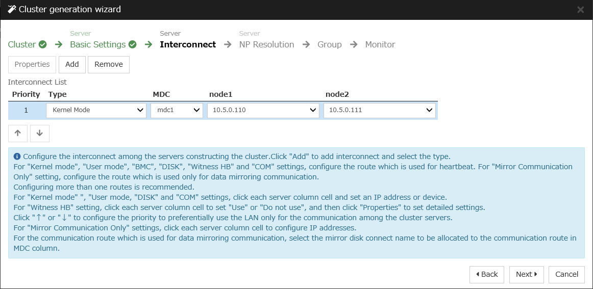
Creating a cluster: Setting the heartbeat method
See "Creating the configuration data of a 2-node cluster" in Creating the cluster configuration data in the Installation and Configuration Guide.
The COM heartbeat, BMC heartbeat, and disk heartbeat cannot be used.
HA cluster using a load balancer
For Microsoft Azure, execute steps 1 to 5, and 7 to 8 in the following table after logging in to the Microsoft Azure portal (https://portal.azure.com/).For Microsoft Azure, execute steps 6, and 9 to 16 after logging in to each virtual machine.
Before Installing EXPRESSCLUSTER
Step No.
Procedure
On-premise
Microsoft Azure
1
Creating a resource group
Not required
2
Creating a virtual network
Not required
3
Creating a virtual machine
Not required
4
Setting a private IP address
Not required
5
Adding a disk
Not required
7
Creating and configuring a load balancer
Not required
8
Setting the inbound security rules
Not required
"5.2. Configuring Microsoft Azure" in this guide
9
Adjusting the OS startup time
See "Settings after configuring hardware" in Determining a system configuration in the Installation and Configuration Guide.
Same as "On-premise"
10
Checking the network setting
See "Settings after configuring hardware" in Determining a system configuration in the Installation and Configuration Guide.
Same as "On-premise"
11
Checking the root file system
See "Settings after configuring hardware" in Determining a system configuration in the Installation and Configuration Guide.
Same as "On-premise"
12
Checking the firewall setting
See "Settings after configuring hardware" in Determining a system configuration in the Installation and Configuration Guide.
Same as "On-premise"
13
Synchronizing the server time
See "Settings after configuring hardware" in Determining a system configuration in the Installation and Configuration Guide.
Same as "On-premise"
14
Checking the SELinux setting
See "Settings after configuring hardware" in Determining a system configuration in the Installation and Configuration Guide.
Same as "On-premise"
15
Installing EXPRESSCLUSTER
See "Installing EXPRESSCLUSTER" in the Installation and Configuration Guide.
Same as "On-premise"
After Installing EXPRESSCLUSTER
Step No.
Procedure
On-premise
Microsoft Azure
16
Registering the EXPRESSCLUSER license
See Registering the license in the Installation and Configuration Guide.
Same as "On-premise"
17
Creating a cluster: Setting the heartbeat method
See "Creating the configuration data of a 2-node cluster" in Creating the cluster configuration data in the Installation and Configuration Guide.
The COM heartbeat, BMC heartbeat, and DISK heartbeat cannot be used.
3. Operating Environments
3.1. HA cluster using Azure DNS
See the following:
"Getting Started Guide" > "Installation requirements for EXPRESSCLUSTER" > "Operation environment for Azure DNS resource, Azure DNS monitor resource"
x86_64
OS
CentOS 7.6
EXPRESSCLUSTER
EXPRESSCLUSTER X 4.2 for Linux (Internal version: 4.2.0-1)
Microsoft Azure deployment model
Resource Manager
Region
(Asia Pacific) Japan East
Mirror disk sizeDisk size: 20 GB(1 GB for a cluster partition and 19 GB for a data partition)Azure CLI
Azure CLI 2.0
Python
2.7
The Azure CLI and Python must be installed because Azure DNS resource use them.Since Python 2.7 is required when using Azure CLI 2.0.For details about the Azure CLI, see the following website:Get started with Azure CLI:Install the Azure classic CLI:Python is bundled with Linux OS.
Since Azure CLI 1.0 (Azure classic CLI) running on Python 2.6 has been unrecommended, install Python by using the package manager of each distribution (e.g. APT, yum, and zipper) if Python 2.7 is not bundled.
Azure DNS must be installed because the Azure DNS resource use it. For details about Azure DNS, see the following website:
3.2. HA cluster using a load balancer
See the following:
"Operation environment for Azure probe port resource, Azure probe port monitor resource, Azure load balance monitor resource" in "Installation requirements for EXPRESSCLUSTER" in the Getting Started Guide.
4. Cluster Creation Procedure (for an HA Cluster Using Azure DNS)
4.1. Creation example
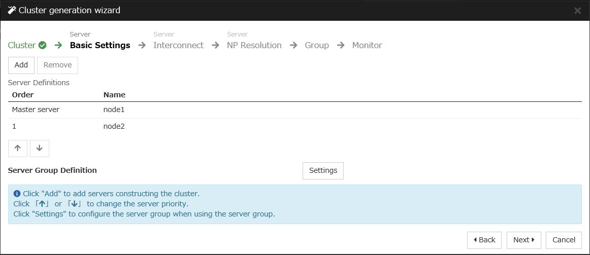
This guide introduces the procedure for creating a 2-node unidirectional standby cluster using EXPRESSCLUSTER. This procedure is intended to create a mirror disk type configuration in which node1 is used as an active server.
The following tables describe the parameters that do not have a default value and the parameters whose values are to be changed from the default values.
Microsoft Azure settings (common to node1 and node2)
Setting item
Setting value
Resource group setting
Resource group
TestGroup1
Region
(Asia Pacific) Japan East
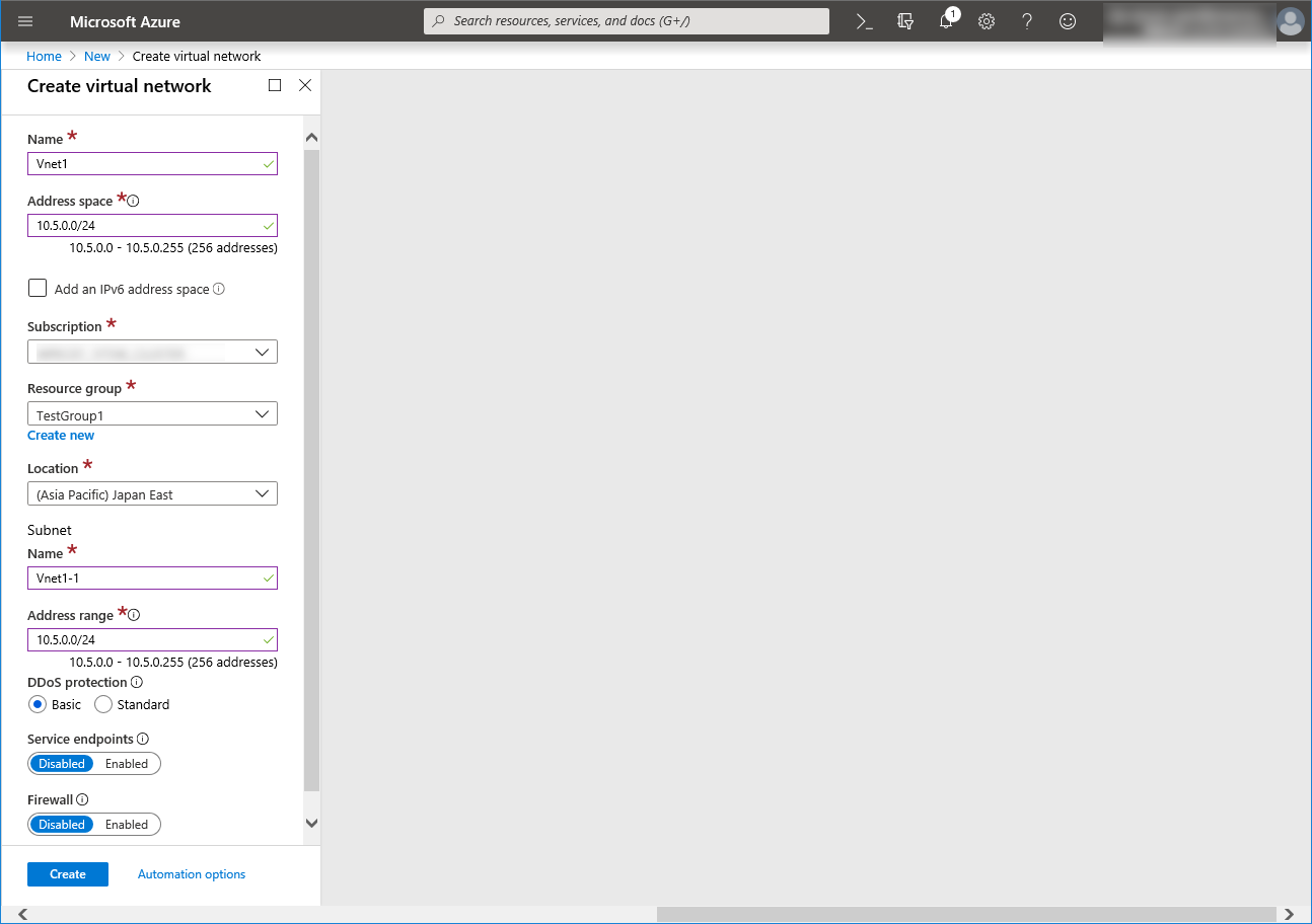
Virtual network setting
Name
Vnet1
Address space
10.5.0.0/24
Subnet Name
Vnet1-1
Subnet Address range
10.5.0.0/24
Resource group
TestGroup1
Location
(Asia Pacific) Japan East
DNS zone setting
Name
cluster1.zone
Resource group
TestGroup1
Record set
test-record1
Microsoft Azure settings (specific to each of node1 and node2)
Setting item
Setting value
node1
node2
Virtual machine setting
Disk type
Standard HDD
User name
testlogin
Password
PassWord_123
Resource group
TestGroup1
Region
(Asia Pacific) Japan East
Network security group setting
Name
node1-nsg
node2-nsg
Availability set setting
Name
AvailabilitySet1
Update domains
5
Fault domains
2
Diagnostics storage account setting
Name
Automatically generated
Performance
Standard
Replication
Locally-redundant storage (LRS)
IP configuration setting
IP address
10.5.0.110
10.5.0.111
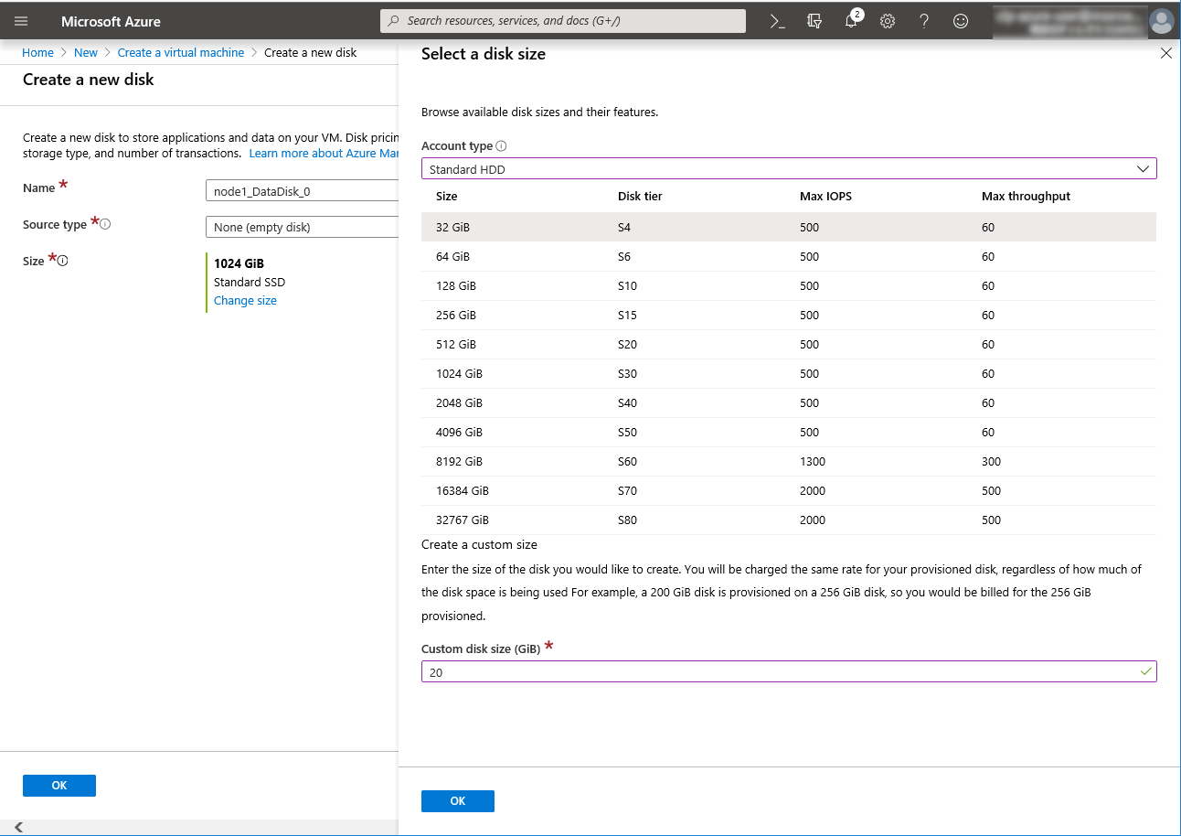
Disk setting
Name
node1_DataDisk_0
node2_DataDisk_0
Source type
None (empty disk)
Account type
Standard HDD
Size
20
EXPRESSCLUSTER settings (cluster properties)
Setting item
Setting value
node1
node2
Cluster Name
Cluster1
Server Name
node1
node2
Timeout Tab: Heartbeat timeout
120
EXPRESSCLUSTER settings (failover group)
Resource name
Setting item
Setting value
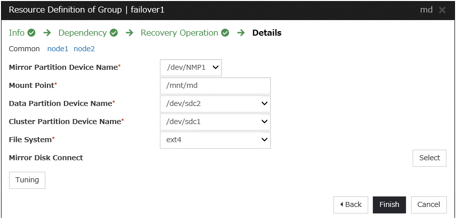
Mirror disk resource
Name
md
Details Tab: Mount Point
/mnt/md
Details Tab: Data Partition Device Name
/dev/sdc2
Details Tab: Cluster Partition Device Name
/dev/sdc1
Details Tab: File System
ext4
Mirror Tab: Execute the initial mirror construction
On
Mirror Tab: Execute initial mkfs
On
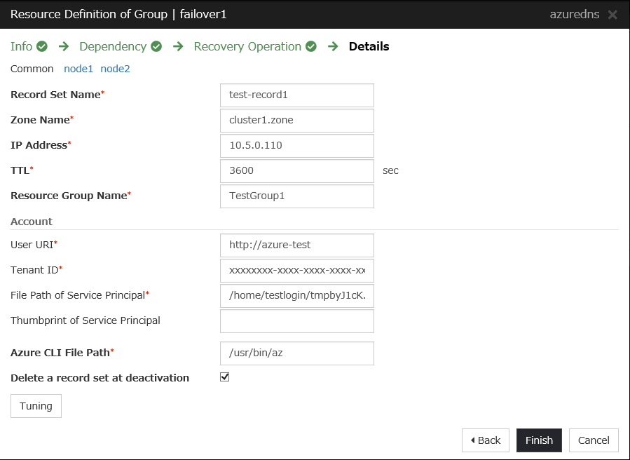
Azure DNS resource
Name
azuredns1
Record Set Name
test-record1
Zone Name
cluster1.zone
IP Address
(node1) 10.5.0.110(node2) 10.5.0.111Resource Group Name
TestGroup1
User URI
http://azure-test
Tenant ID
xxxxxxxx-xxxx-xxxx-xxxx-xxxxxxxxxxxx
File Path of Service Principal
/home/testlogin/tmpbyJ1cK.pem
Azure CLI File Path
/usr/bin/az
EXPRESSCLUSTER settings (monitor resource)
Monitor resource name
Setting item
Setting value
Mirror disk monitor resource
Name
mdw1
Azure DNS monitor resource
Name
azurednsw1
Custom monitor resource
Name
genw1
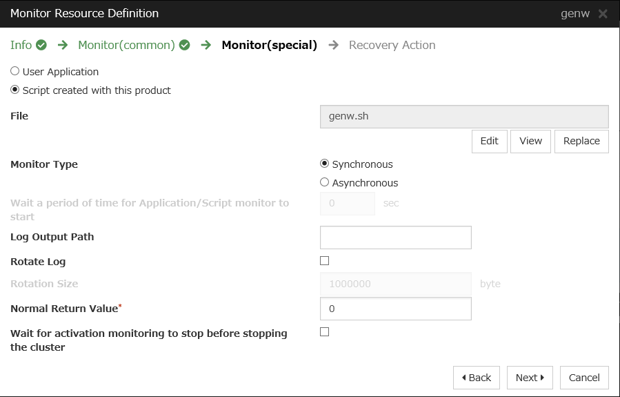
Script created with this product
On
Monitor Type
Synchronous
Normal Return Value
0
Recovery Action
Execute only the final action
Recovery Target
LocalServer
IP monitor resource
Name
ipw1
Server to monitor
node1
IP Address
10.5.0.111
Recovery Action
Execute only the final action
Recovery Target
LocalServer
IP monitor resource
Name
ipw2
Server to monitor
node2
IP Address
10.5.0.110
Recovery Action
Execute only the final action
Recovery Target
LocalServer
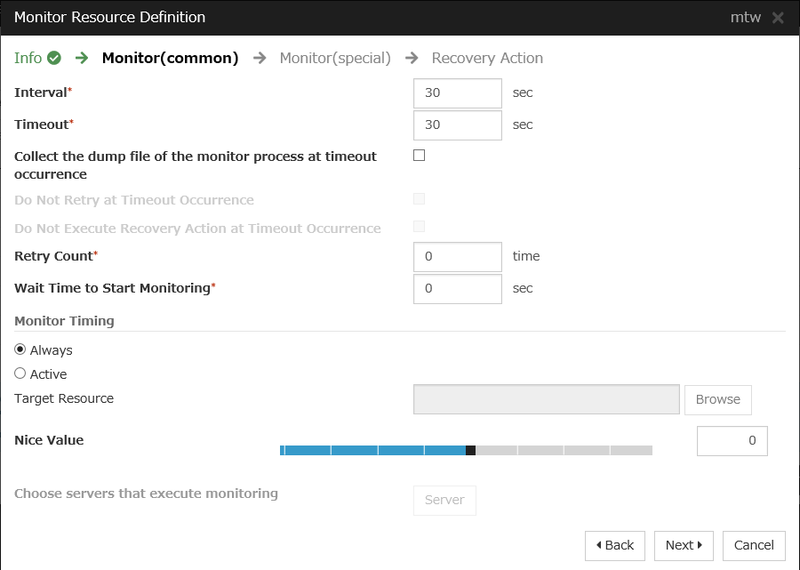
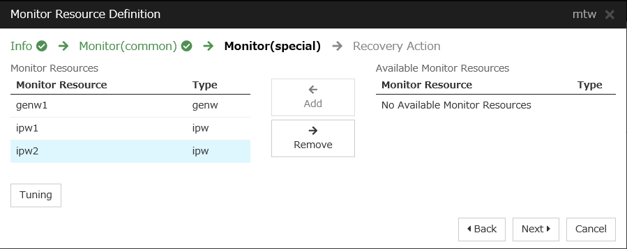
Multi target monitor resource
Name
mtw1
Monitor resource list
genw1ipw1ipw2Recovery Action
Execute only the final action
Recovery Target
LocalServer
4.2. Configuring Microsoft Azure
Creating a resource group
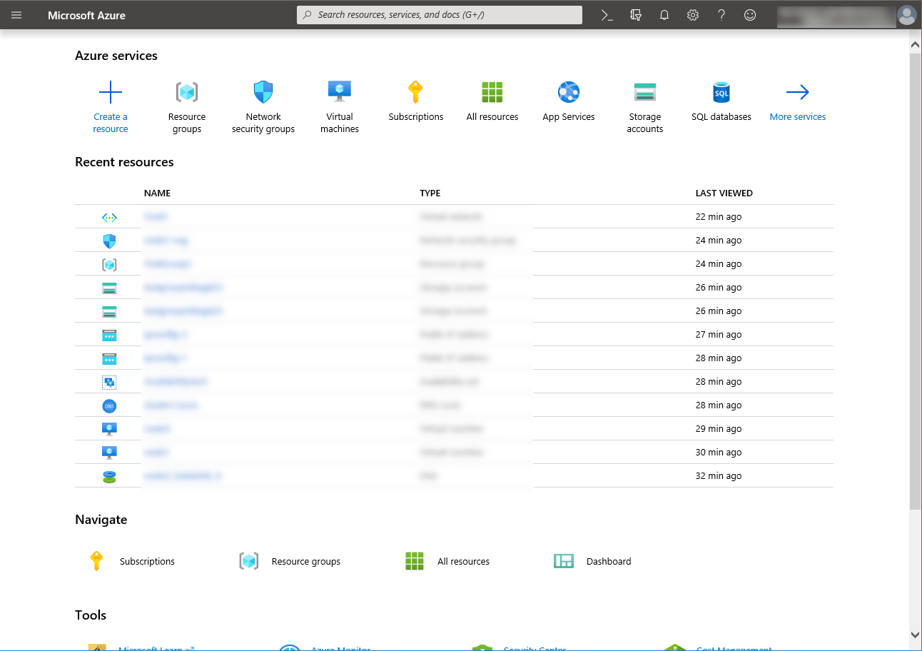
Log in to the Microsoft Azure portal (https://portal.azure.com/) and create a resource group following the steps below.
Select the Resource groups icon on the upper part of the window. If there are existing resource groups, they are displayed in a list.
Select +Add on the upper part of the window.

Specify Subscription, Resource group, and Region, and click Review+Create.

Creating a virtual network
Log in to the Microsoft Azure portal (https://portal.azure.com/) and create a virtual network following the steps below.
Select the +Create a resource icon on the upper part of the window.
Select Networking and then Virtual network.
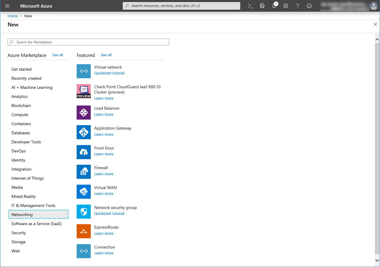
Specify Name, Address space, Subscription, Resource group, Location, Name of Subnet, and Address range of Subnet, and click Create.
Creating a virtual machine
Log in to the Microsoft Azure portal (https://portal.azure.com/) and create virtual machines and disks following the steps below.Create as many virtual machines as required to create a cluster. Create node1 and then node2.Select the Create a resource icon on the upper part of the window.
Select Compute and then See all.

Select CentOS-based 7.6.

Click Create.
- When the Basics tab appears, specify the settings of Subscription, Resource group, Virtual machine name, Region, Image, Size, Username, Password, and Confirm password.Select Availability set from Availability options, and click Create new under the Availability set field. When Create new appears, specify the settings of Name, Fault domains, and Update domains. Then click OK.

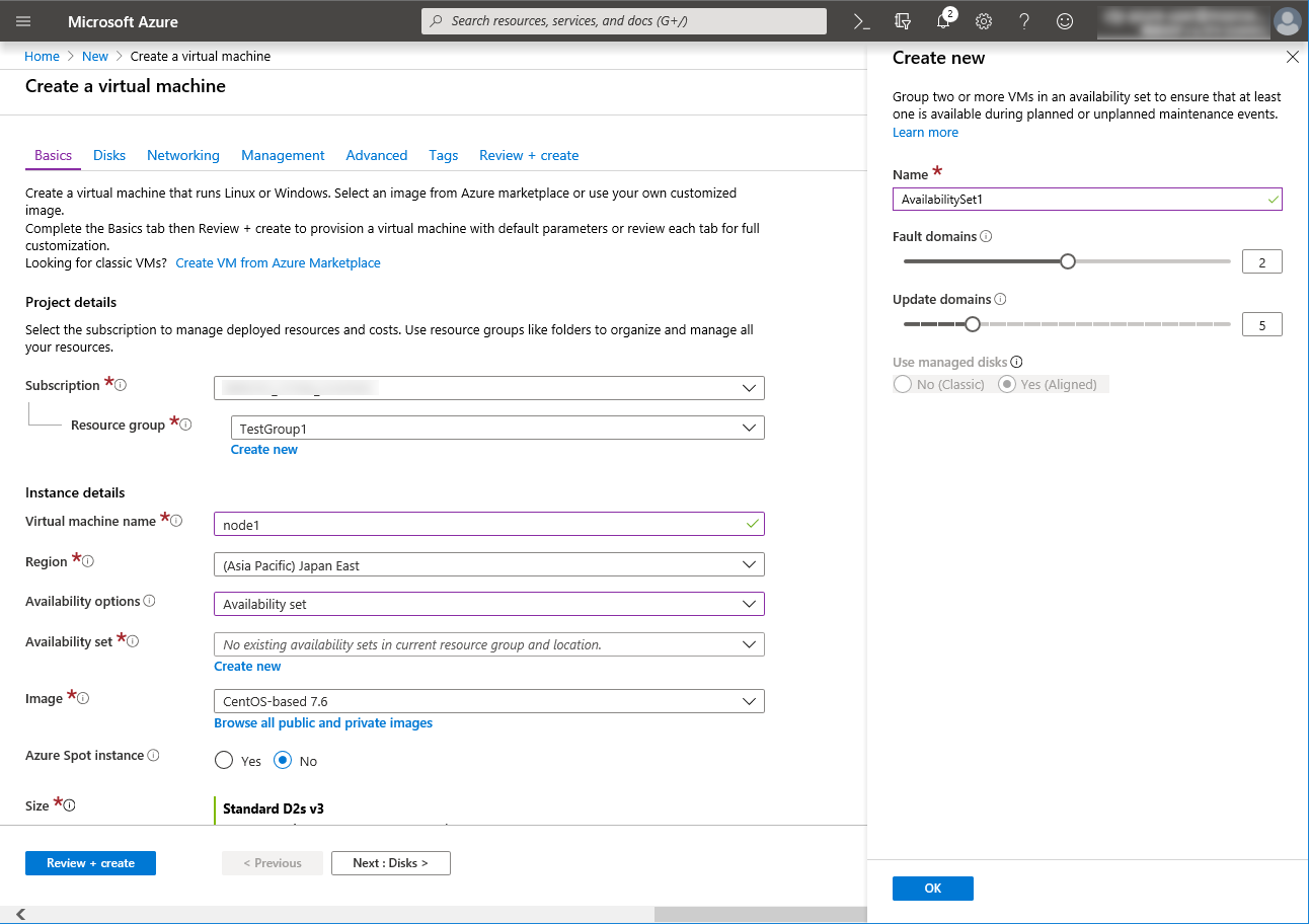
- Click Change size to display Select a VM size.From the list, choose a size (Standard - A1 in this guide) suitable for your virtual machine and click Select.Regarding the Virtual machine name, node1 is for node1, and node2 is for node2.Click Next: Disks >
- When the Disks tab appears, go through the following steps to add a disk to be used for a mirror disk (cluster partition or data partition).From the DATA DISKS list, click Create and attach a new disk.
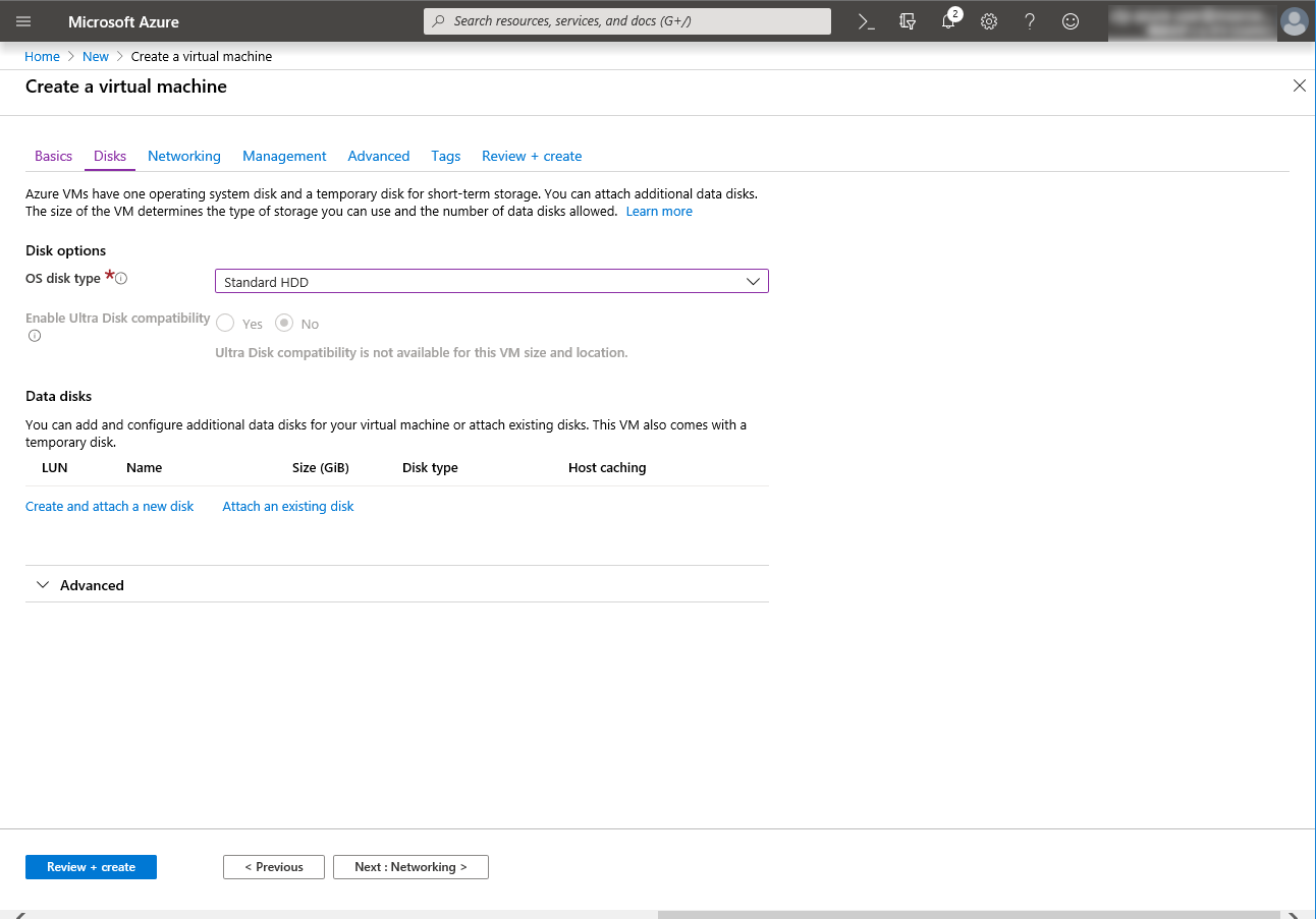
- Create a new disk appears.Specify the settings of**Name**, Source type, and Size. Then click OK.Click Next: Networking >
- The Networking tab appears.Specify the settings of Virtual network, Subnet, NIC Network security group, and Configure network security group.Click Create new under the Configure network security group field to display Create network security group. Specify the setting of Name and then click OK.Click Next: Management >.

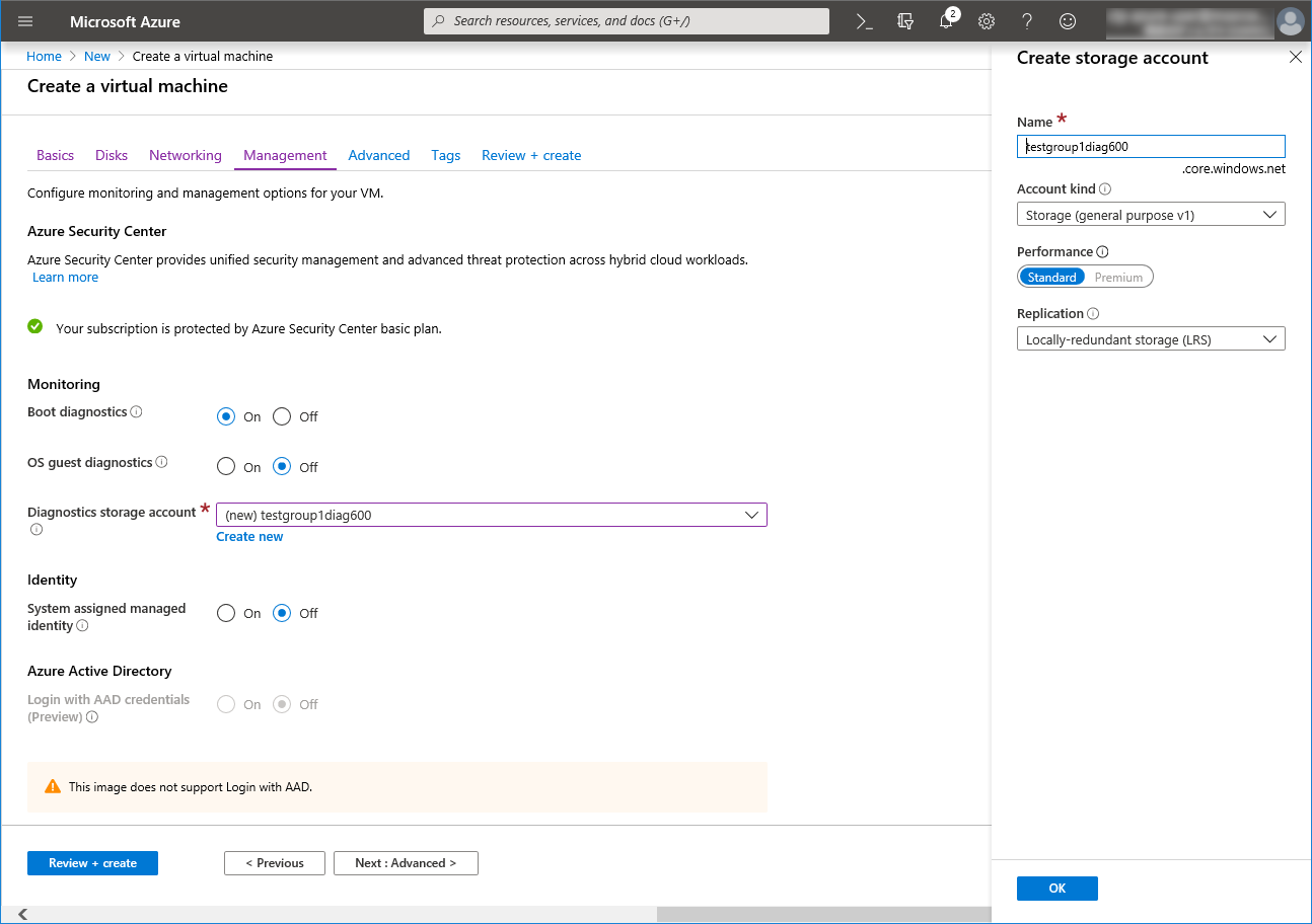
- The Management tab appears.Click Create new under the Diagnostics storage account field to display Create storage account.Specify the settings of Name, Account kind, and Replication. Then click OK.In the Diagnostics storage account field, the default value is automatically generated and entered.Click Next: Details >.

Click Next: Tags >.

Click Next: Review + create >.
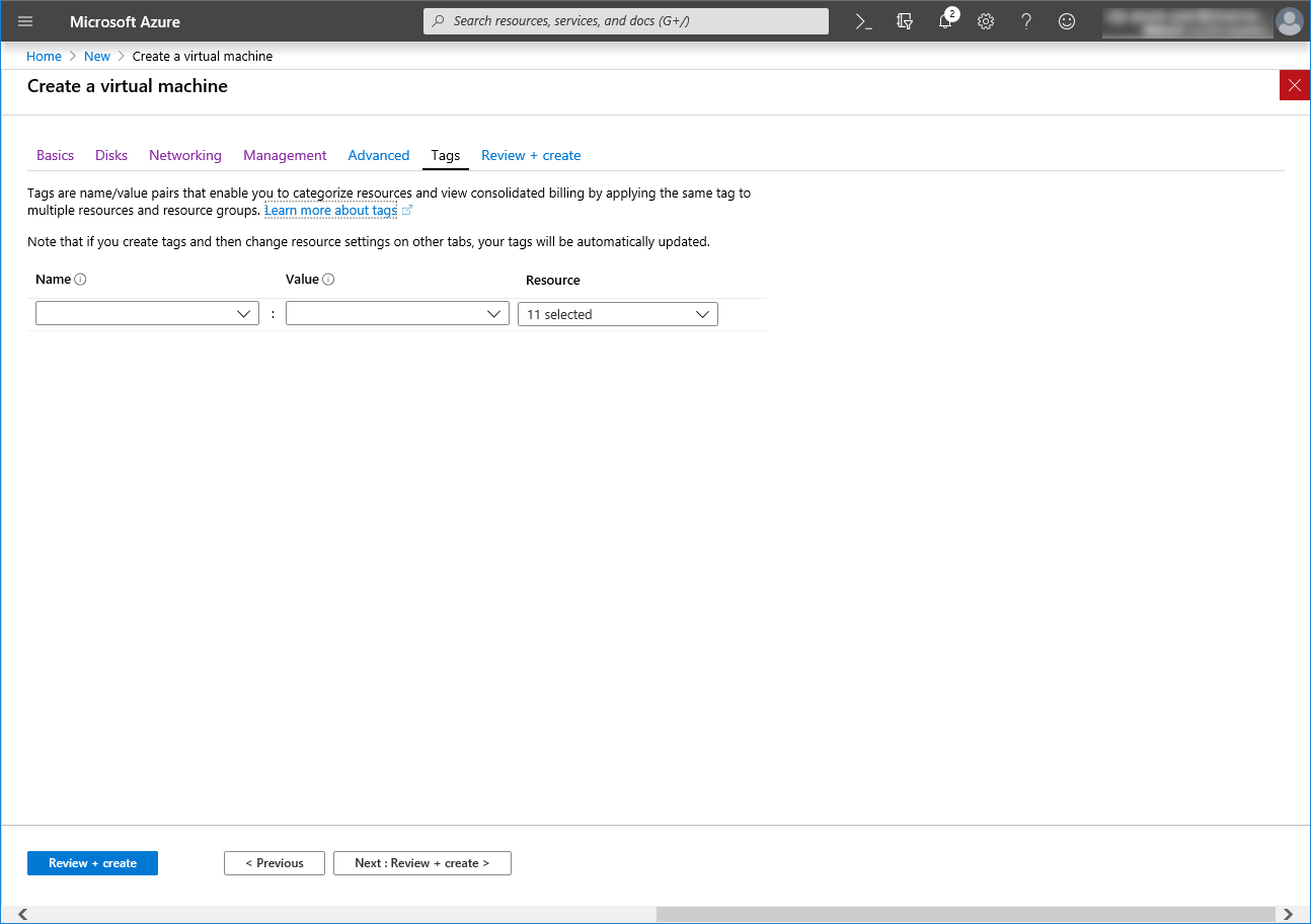
The Review + create tab appears. Check the contents. If there is no problem, click Create. The deployment starts and takes several minutes.

Setting a private IP address
Log in to the Microsoft Azure portal (https://portal.azure.com/) and change the private IP address setting following the steps below. Since an IP address is initially set to be assigned dynamically, change the setting so that an IP address is assigned statically. Change the settings of node1 and then node2.
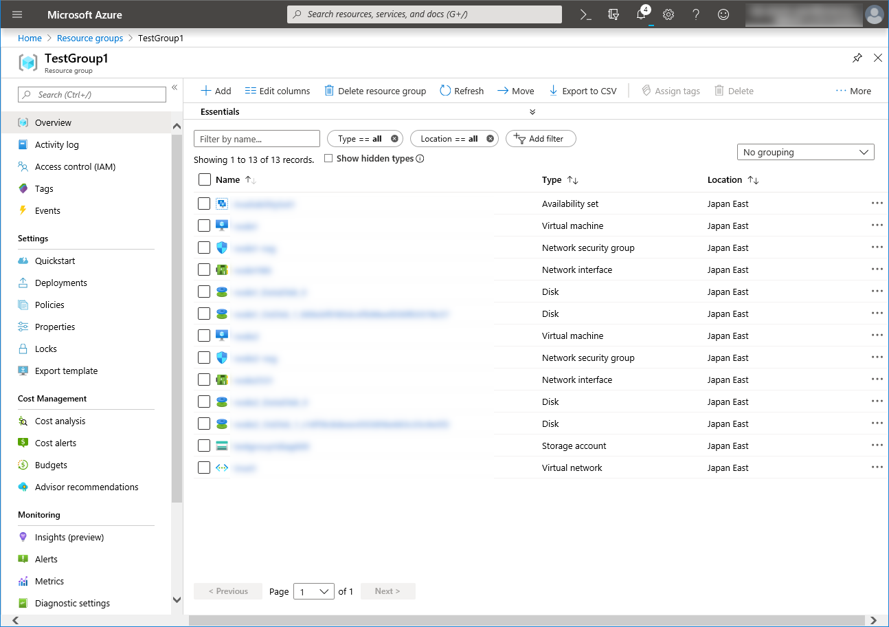
Select the Resource groups icon on the upper part of the window.
Select TestGroup1 from the resource group list.
The summary of TestGroup1 is displayed. Select virtual machine node1 or node2 from the item list.

Select Networking.
Select a network interface displayed in the list. The network interface name is generated automatically.
Select IP configurations.
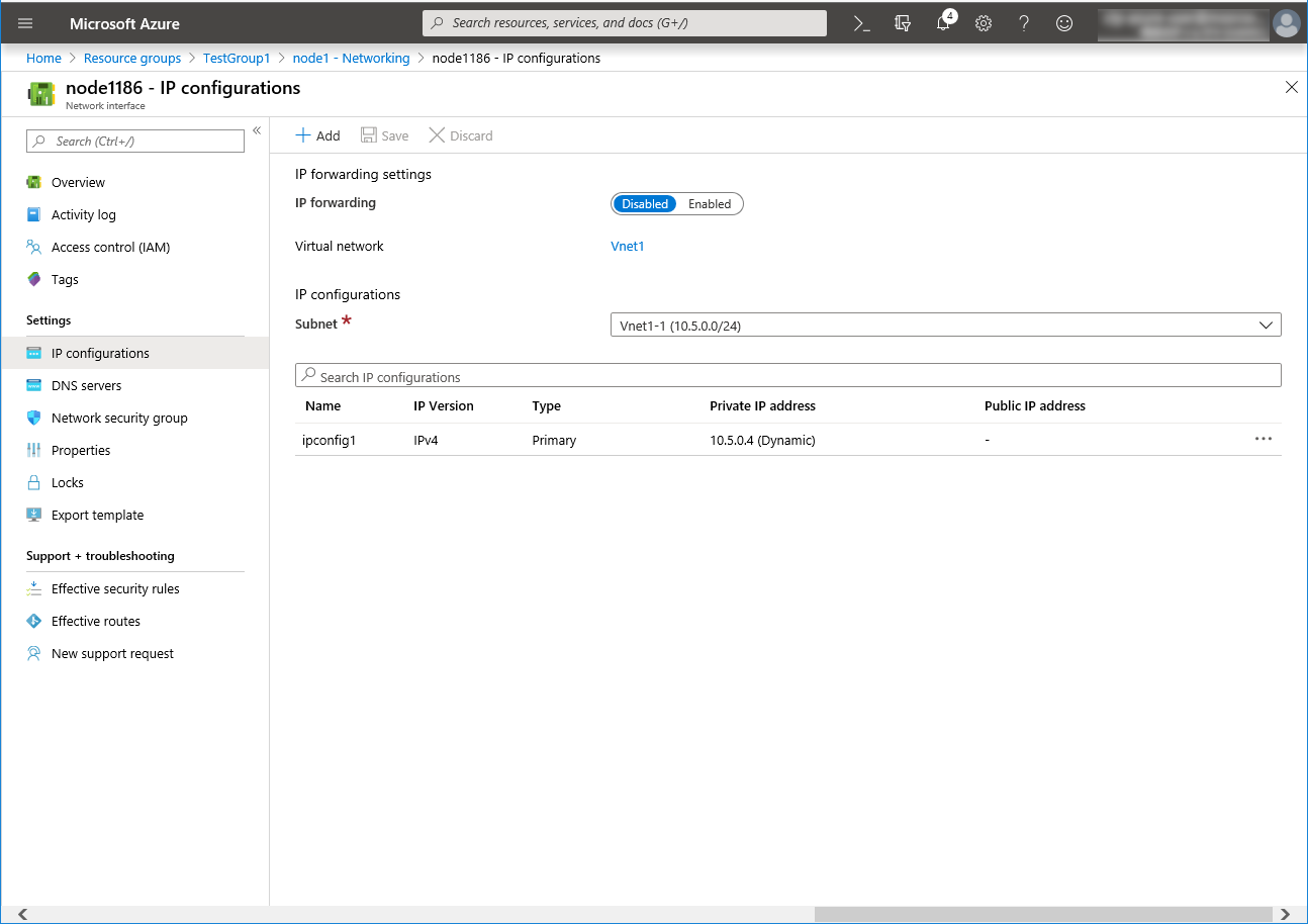
Only ipconfig1 is displayed in the list. Select it.
Select Static for Assignment under Private IP address settings. Enter the IP address to be assigned statically in the IP address text box and click Save at the top of the window. The IP address of node1 is 10.5.0.110. The IP address of node2 is 10.5.0.111.

The virtual machines restart automatically so that new private IP addresses can be used.
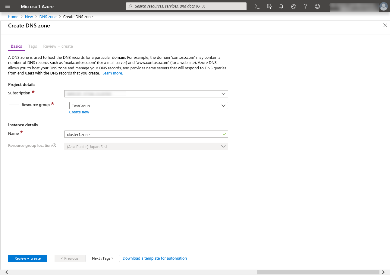
Creating a DNS zone
Log in to the Microsoft Azure portal (https://portal.azure.com/) and configure the DNS zone following the steps below.
Select the Create a resource icon on the upper part of the window.
Select Networking and then See all. Search for DNS zone.
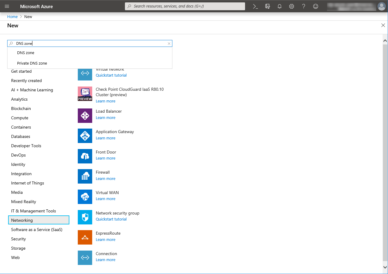
Create DNS zone is displayed. Specify Subscription, Resource group, and Name, and click Review+create. Then click Create.
Configuring virtual machines
Log in to the created node1 and node2 and specify the settings following the procedure below.
Set a partition for the mirror disk resource. Create a file system in the added disk.
Secure an area in the added disk by using the fdisk command and then create a file system.
For details about the partition for the mirror disk resource, see "Partition settings for Mirror disk resource (when using Replicator)" in "Settings after configuring hardware" in "Determining a system configuration" in the Installation and Configuration Guide.
Check the partition list. In the following example, the last line shows the added disk.
$ cat /proc/partitions
major minor  #blocks  name

   2        0          4 fd0
   8        0   31457280 sda
   8        1     512000 sda1
   8        2   30944256 sda2
   8       16   73400320 sdb
   8       17   73398272 sdb1
   8       32   20971520 sdc
Create a cluster partition and data partition in the added disk by using the fdisk command. Allocate 1 GB (1*1024*1024*1024 bytes) or more to a cluster partition. (If the size is specified as just 1 GB, the actual size will be larger than 1 GB depending on the disk geometry difference. This is not a problem.) Also, do not create a file system in a cluster partition.
If you select Execute initial mkfs when creating the cluster configuration data by using Cluster WebUI, EXPRESSCLUSTER creates a file system automatically. Note that existing data in the partition will be lost.
Adjusting the OS startup time, checking the network setting, checking the root file system, checking the firewall setting, synchronizing the server time, and checking the SELinux setting.
For each procedure, see "Settings after configuring hardware." in "Determining a system configuration" in the Installation and Configuration Guide.Installing the Azure CLI
Install the Azure CLI.The procedure to install the Azure CLI from an npm package is described.For details about this procedure and other procedures, see the following websites:Install the Azure CLI:Log in to the created node1 and node2 and install the Azure CLI following the procedure below.Be sure to use the following installation procedure. If the Azure CLI is installed in other ways, Azure DNS resource will not work properly.$ sudo yum check-update; sudo yum install -y gcc libffi-devel python-devel openssl-devel $ curl -L https://aka.ms/InstallAzureCli | bash - $ exec -l $SHELL
Creating a service principal
Create a service principal using the Azure CLI.Azure DNS resource performs login to Microsoft Azure and DNS zone registration and monitoring. When logging in to Microsoft Azure, Azure login with a service principal is used.Please note that certificates have an expiration date.For more details, see the --years option of az ad sp create-for-rbac.For details about a service principal and procedure, see the following websites:
Sign in with Azure CLI:Create an Azure service principal with Azure CLI:Log in with an organizational account.
$ az login -u <account_name> -p <password>Create and register a service principal. Write down the displayed name and tenant because it is necessary to set them in the Azure DNS resource settings of Cluster WebUI. In the following example, a service principal is created in /home/testlogin/tmpbyJ1cK.pem. The valid period of certificates is set to 10 years.
$ az ad sp create-for-rbac --name azure-test --create-cert --years 10
{
  "appId": "xxxxxxxx-xxxx-xxxx-xxxx-xxxxxxxxxxxx",
  "displayName": "azure-test",
  "fileWithCertAndPrivateKey": "/home/testlogin/tmpbyJ1cK.pem",
  "name": "http://azure-test",
  "password": null,
  "tenant": "xxxxxxxx-xxxx-xxxx-xxxx-xxxxxxxxxxxx""
}
Log out.
$ az logout --u <account_name>Check whether login to Microsoft Azure using the created service principal is possible.
$ az login --service-principal -u <name_value_in_step_2> --tenant <tenant_value_in_step_2> -p <fileWithCertAndPrivateKey_value_in_step_2>The following is displayed upon successful sign-in.
[
  {
    "cloudName": "AzureCloud",
    "id": "xxxxxxxx-xxxx-xxxx-xxxx-xxxxxxxxxxxxx",
    "isDefault": true,
    "name": "xxxxxxxxxx",
    "state": "Enabled",
    "tenantId": "xxxxxxxx-xxxx-xxxx-xxxx-xxxxxxxxxxxx",
    "user": {
      "name": "http://azure-test",
      "type": "servicePrincipal"                }
  }
]
Log out.
$ az logout --username <name_value_in_step_4>When changing the role of the created service principal from the default "Contributor" to another role, select a role that has access permissions to all of the following operations as the Actions properties. If the role is changed to a role that does not satisfy this condition, monitoring by the Azure DNS monitor resource, which are set up later, will fail due to an error.
Microsoft.Network/dnsZones/A/writeMicrosoft.Network/dnsZones/A/deleteMicrosoft.Network/dnsZones/NS/read
Installing EXPRESSCLUSTER
For the installation procedure, see the Installation and Configuration Guide.After installation is complete, restart the OS.Registering the EXPRESSCLUSER license
For the license registration procedure, see the Installation and Configuration Guide.
4.3. Configuring the EXPRESSCLUSTER settings
For the Cluster WebUI setup and connection procedures, see "Creating the cluster configuration data" in the Installation and Configuration Guide.
This section describes the procedure to add the following resources and monitor resources:
Mirror disk resource
Azure DNS resource
Azure DNS monitor resource
Custom monitor resource (for NP resolution)
IP monitor resource (for NP resolution)
Multi target monitor resource (for NP resolution)
For the settings of other resources and monitor resources, see the Installation and Configuration Guide and the Reference Guide.
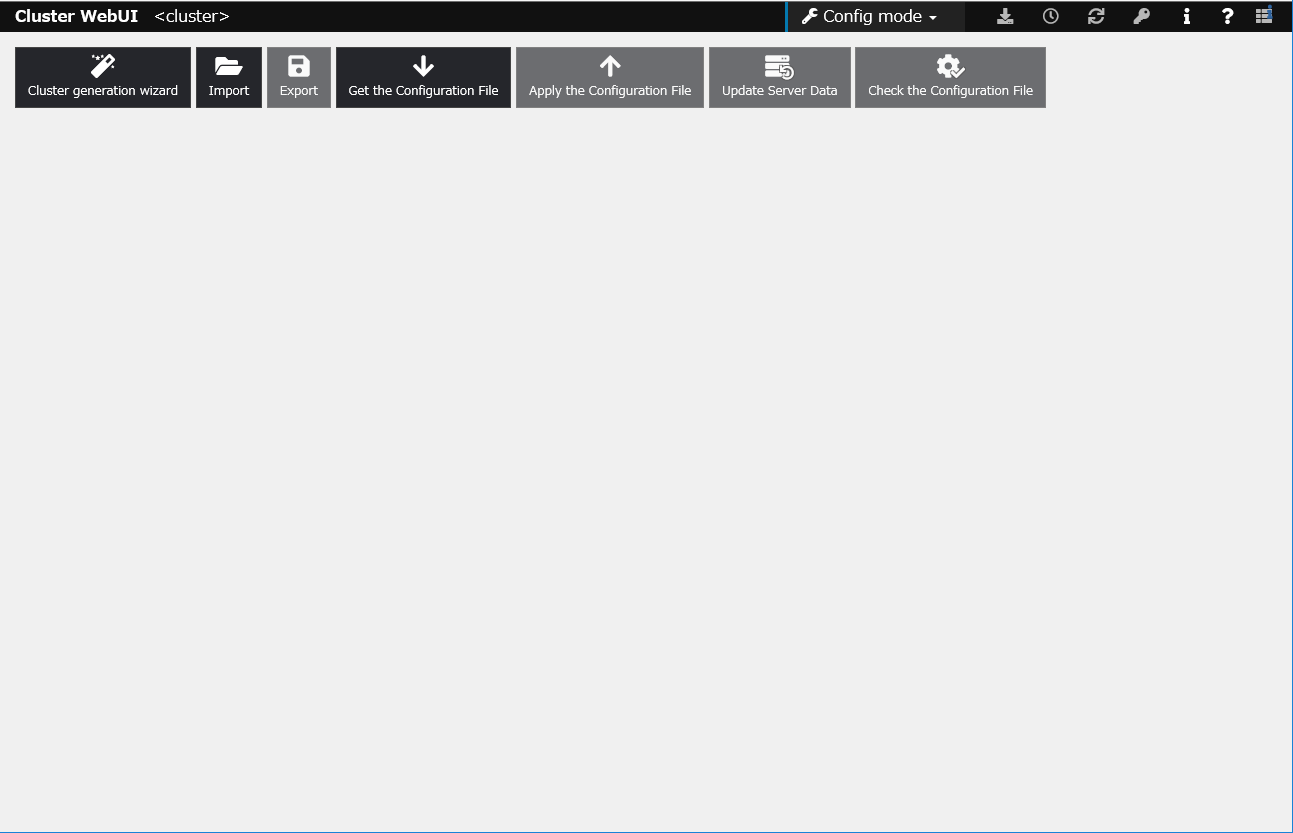
Creating a cluster
Start the Cluster generation wizard to create a cluster.
Creating a cluster
.Access Cluster WebUI, and click Cluster generation wizard.

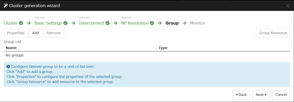
Adding a group resource
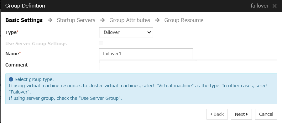
Defining a group
Create a failover group.
Mirror disk resource
Create a mirror disk resource.For details, see "Understanding mirror disk resources" in the Reference Guide.
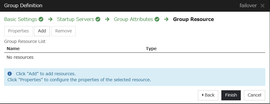
Click Add on the Group Resource List page.
Azure DNS resource
Provides a mechanism to register or unregister a record to or from Azure DNS.For details about the Azure DNS resource, see "Understanding Azure DNS resources" in the Reference Guide.
Click Add on the Group Resource List page.
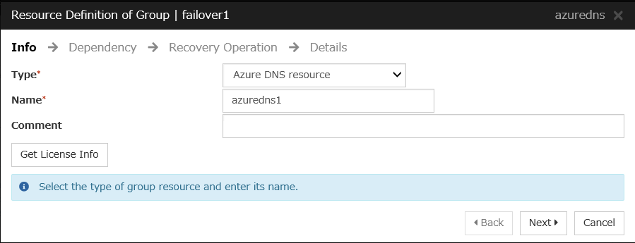
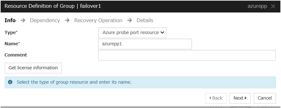
The Resource Definition of Group | failover1 window is displayed. Select the group resource type (Azure DNS resource) from the Type box and enter the group name (azuredns1) in the Name box. Click Next.
Click Finish.

Adding a monitor resource
Azure DNS monitor resource
The mechanism to check the record sets registered to the Azure DNS and whether the name resolution is available is provided.For details about Azure DNS monitor resources, see "Reference Guide" > "Understanding Azure DNS monitor resources"Adding one Azure DNS resource creates one Azure DNS monitor resource automatically.Custom monitor resource
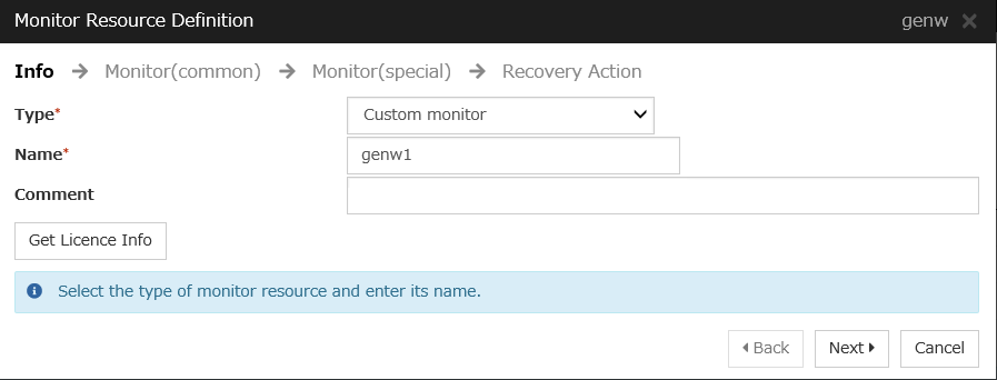
Sets a script to monitor whether communication with the Microsoft Azure Service Management API is possible, and also to monitor health of communication with an external network.For details about the custom monitor resource, see "Understanding custom monitor resources" in the Reference Guide.
Click Add on the Monitor Resource List page.
Select the monitor resource type (Custom monitor) from the Type box and enter the monitor resource name (genw1) in the Name box. Click Next.
Click Finish to finish setting.
IP monitor resource
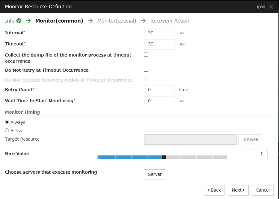
Creates an IP monitor resource to monitor communication between clusters that are configured with virtual machines, and also to monitor whether communication with an internal network is health.For details about the IP monitor resource, see Understanding IP monitor resources in the Reference Guide.
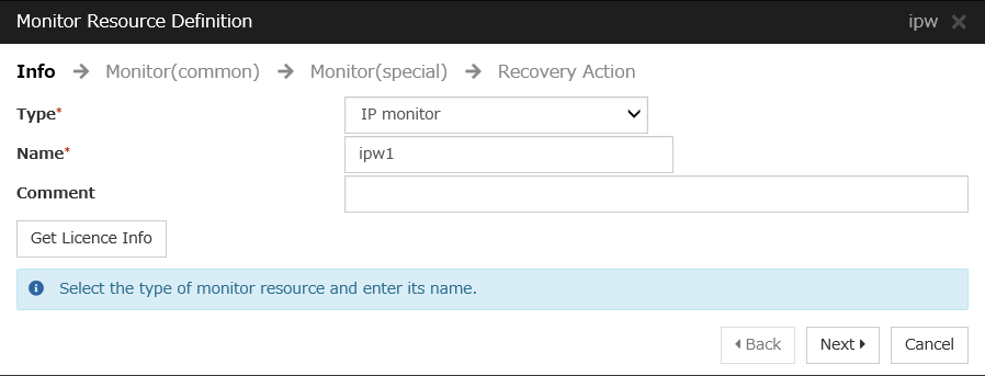
Click Add on the Monitor Resource List page.
Select the monitor resource type (IP monitor) from the Type box and enter the monitor resource name (ipw1) in the Name box. Click Next.
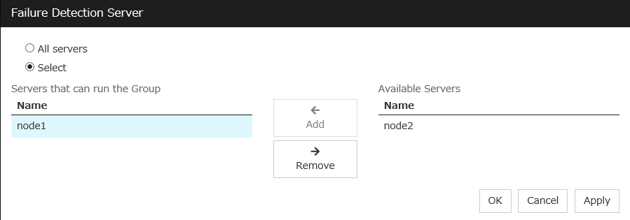
Select one available server for Choose servers that execute monitoring.
Click Next.
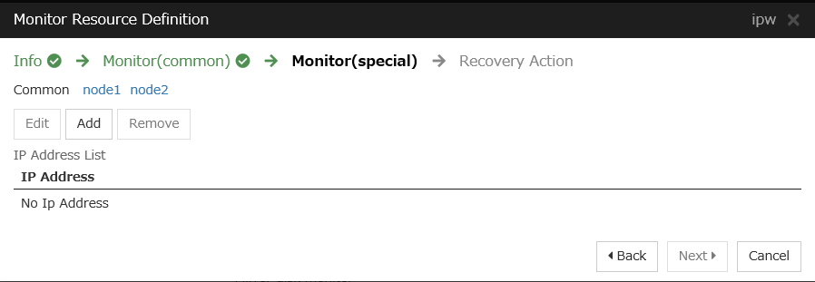
The Monitor (special) window is displayed.
On the Common tab, select Add of IP Address and set an IP address of a server other than the server selected in step 3. Click Next.
Click Finish to finish setting.
Then, create a monitor resource on the other server. Click Add on the Monitor Resource List page.
Select the monitor resource type (IP monitor) from the Type box and enter the monitor resource name (ipw2) in the Name box. Click Next.
Click Finish to finish setting.
Multi target monitor resource
Creates a multi target monitor resource to check the statuses of both the custom monitor resource monitoring communication to Microsoft Azure Service Management API and the IP monitor resource between clusters that are configured with virtual machines.If the statuses of both monitor resources are abnormal, execute the script in which the processing for NP resolution is described.For details about the multi target monitor resource, see Understanding multi target monitor resources in the Reference Guide.
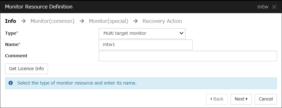
Click Add on the Monitor Resource List page.
Select the monitor resource type (Multi target monitor) from the Type box and enter the monitor resource name (mtw1) in the Name box. Click Next.
Click Finish.


Setting the cluster properties
For details about the cluster properties, see "Cluster properties" in the Reference Guide.
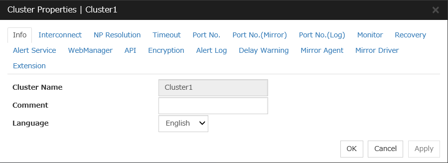
Cluster properties
Configure the settings in Cluster Properties to link Microsoft Azure and EXPERSSCLUSTER.
Enter Config Mode from Cluster WebUI, click the property icon of a cluster name.
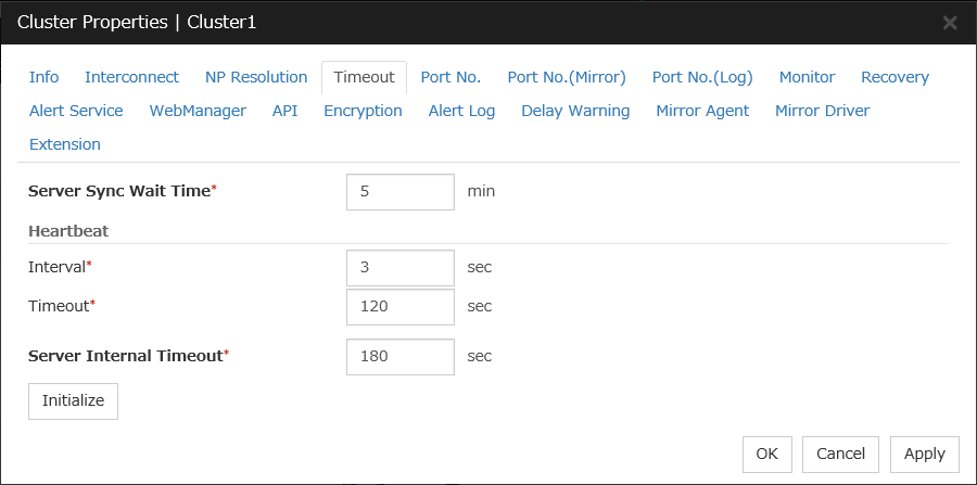
Select the Timeout tab. For Timeout of Heartbeat, specify a value calculated by "A+B+C" as described below.
A: Interval of the monitor resource being monitored by the multi target monitor resource for NP resolution x (Retry Count+1)
* Among three monitor resources, select the monitor resource whose calculation result is the largest.
B: Interval of the multi target monitor resource x (Retry Count+1)
C: 30 seconds (Waiting time for heartbeat not to time out before the multi target monitor resource detects an error. The time can be changed accordingly.
Note
If Timeout of Heartbeat is shorter than the time that it took for the multi target monitor resource to detect an error, a heartbeat timeout will be detected before starting the NP resolution processing. In this case, the same service may start doubly in the cluster because the service also starts on the standby server.
Click OK.
Applying the settings and starting the cluster
Select the Operation Mode on the drop down menu of the toolbar in Cluster WebUI to switch to the operation mode.
The procedure depends on the resource used. For details, refer to the following:Installation and Configuration Guide -> How to create a cluster
4.4. Verifying the created environment
Start the failover group (failover1) on the active node (node1). In the Status tab on the Cluster WebUI, confirm that Group Status of failover1 of node1 is Normal.
Log in to the Microsoft Azure portal, select cluster1.zone on the DNS zone, and then select Summary. Check the DNS servers displayed on the upper right of the window (name server 1, name server 2, name server 3, and name server 4 in the window example).
Confirm that the relevant record set exists in the DNS servers checked in the above step by executing the nslookup command as follows:
$ nslookup test-record1.cluster1.zone <DNS_servers_checked_in_the_above_step>On the Microsoft Azure portal, delete an A record from the DNS zone. This causes azurednsw1 to detect a monitoring error. On the DNS zone, select cluster1.zone and then Summary.
Select the record you want to delete and click Delete. When the deletion confirmation dialog box is displayed, select Yes.
When the time specified for Interval of azurednsw1 elapses, the failover group (failover1) enters an error status and fails over to node2. In the Status tab on the Cluster WebUI, confirm that Group Status of failover1 of node2 is Normal.
Confirm that the relevant record set exists in the DNS servers checked in the above step by executing the nslookup command as follows:
$ nslookup test-record1.cluster1.zone <DNS_servers_checked_in_the_above_step>
Verifying the failover operation when an A record is deleted from the DNS server is now complete. Verify the operations in case of other failures if necessary.
5. Cluster Creation Procedure (for an HA Cluster Using an Public Load Balancer)
5.1. Creation example
This guide introduces the procedure for creating a 2-node unidirectional standby cluster using EXPRESSCLUSTER on Microsoft Azure. This procedure is intended to create a mirror disk type configuration in which node1 is used as an active server.
The following tables describe the parameters that do not have a default value and the parameters whose values are to be changed from the default values.
Microsoft Azure settings (common to node1 and node2)
Setting item
Setting value
Resource group setting
Resource group
TestGroup1
Region
(Asia Pacific) Japan East
Virtual network setting
Name
Vnet1
Address space
10.5.0.0/24
Subnet Name
Vnet1-1
Subnet Address range
10.5.0.0/24
Resource group
TestGroup1
Location
(Asia Pacific) Japan East
Load balancer setting
Name
TestLoadBalancer
Type
Public
Public IP address
TestLoadBalancerPublicIP
Public IP address: Assignment
Static
Resource group
TestGroup1
Region
(Asia Pacific) Japan East
Backend pool: Name
TestBackendPool
Associated to
Availability set
Target virtual machine
node1
node2
Network IP configuration
10.5.0.110
10.5.0.111
Health probe: Name
TestHealthProbe
Health probe: Port
26001
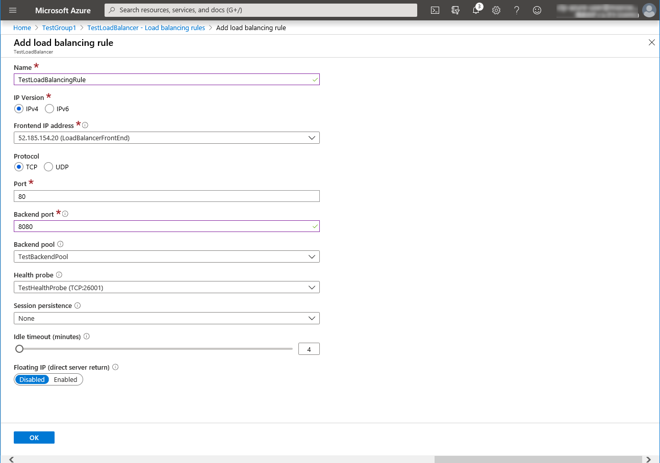
Load balancing rule: Name
TestLoadBalancingRule
Load balancing rule: Port
80 (Port number offering the operation)
Load balancing rule: Backend port
8080 (Port number offering the operation)
Inbound security rule setting
Name
TestHTTP
Protocol
TCP
Destination Port range
8080 (Port number offering the operation)
Microsoft Azure settings (specific to each of node1 and node2)
Setting item
Setting value
node1
node2
Virtual machine setting
Disk type
Standard HDD
User name
testlogin
Password
PassWord_123
Resource group
TestGroup1
Region
(Asia Pacific) Japan East
Network security group setting
Name
node1-nsg
node2-nsg
Availability set setting
Name
AvailabilitySet1
Update domains
5
Fault domains
2
Diagnostics storage account setting
Name
Automatically generated
Performance
Standard
Replication
Locally-redundant storage (LRS)
IP configuration setting
IP address
10.5.0.110
10.5.0.111
Disk setting
Name
node1_DataDisk_0
node2_DataDisk_0
Source type
None (empty disk)
Account type
Standard HDD
Size
20
EXPRESSCLUSTER settings (cluster properties)
Setting item
Setting value
node1
node2
Cluster Name
Cluster1
Server Name
node1
node2
Timeout Tab: Heartbeat timeout
120
EXPRESSCLUSTER settings (failover group)
Resource name
Setting item
Setting value
Mirror disk resource
Name
md
Details Tab: Mount Point
/mnt/md
Details Tab: Data Partition Device Name
/dev/sdc2
Details Tab: Cluster Partition Device Name
/dev/sdc1
Details Tab: File System
ext4
Mirror Tab: Execute the initial mirror construction
On
Mirror Tab: Execute initial mkfs
On
Azure probe port resource
Name
azurepp1
Probe port
26001 (Value specified for Port of Health probe)
EXPRESSCLUSTER settings (monitor resource)
Monitor resource name
Setting item
Setting value
Mirror disk monitor resource
Name
mdw1
Azure probe port monitor resource
Name
azureppw1
Recovery Target
azurepp1
Azure load balance monitor resource
Monitor resource name
aurelbw1
Recovery Target
azurepp1
Custom monitor resource
Name
genw1
Script created with this product
On
Monitor Type
Synchronous
Normal Return Value
0
Recovery Action
Execute only the final action
Recovery Target
LocalServer
IP monitor resource
Name
ipw1
Server to monitor
node1
IP Address
10.5.0.111
Recovery Action
Execute only the final action
Recovery Target
LocalServer
IP monitor resource
Name
ipw2
Server to monitor
node2
IP Address
10.5.0.110
Recovery Action
Execute only the final action
Recovery Target
LocalServer
Multi target monitor resource
Name
mtw1
Monitor resource list
genw1ipw1ipw2Recovery Action
Execute only the final action
Recovery Target
LocalServer
Execute Script before Final Action
On
Timeout
30
5.2. Configuring Microsoft Azure
Creating a resource group
Log in to the Microsoft Azure portal (https://portal.azure.com/) and create a resource group following the steps below.
Select the Resource groups icon on the upper part of the window. If there are existing resource groups, they are displayed in a list.
Select +Add at the upper part of the window.
Specify Subscription, Resource group, and Region, and click Review+Create.
Creating a virtual network
Log in to the Microsoft Azure portal (https://portal.azure.com/) and create a virtual network following the steps below.
Select the Create a resource icon on the upper part of the window.
Select Networking and then Virtual network.
Specify Name, Address space, Subscription, Resource group, Location, Name of Subnet, and Address range of Subnet, and click Create.
Creating a virtual machine
Log in to the Microsoft Azure portal (https://portal.azure.com/) and create virtual machines and disks following the steps below.Create as many virtual machines as required to create a cluster. Create node1 and then node2.
Select the Create a resource icon on the upper part of the window.
Select Compute and then See all.
Select CentOS-based 7.6
Click Create.
Click Next: Tags >.
Click Next: Review + create >.
The Review + create tab appears. Check the contents. If there is no problem, click Create. The deployment starts and takes several minutes.
Setting a private IP address
Log in to the Microsoft Azure portal (https://portal.azure.com/) and change the private IP address setting following the steps below. Since an IP address is initially set to be assigned dynamically, change the setting so that an IP address is assigned statically. Change the settings of node1 and then node2.
Select the Resource groups icon on the upper part of the window.
Select TestGroup1 from the resource group list.
The summary of TestGroup1 is displayed. Select virtual machine node1 or node2 from the item list.
Select Networking.
Select a network interface displayed in the list. The network interface name is generated automatically.
Select IP configurations.
Only ipconfig1 is displayed in the list. Select it.
Select Static for Assignment under Private IP address settings. Enter the IP address to be assigned statically in the IP address text box and click Save at the top of the window. The IP address of node1 is 10.5.0.110. The IP address of node2 is 10.5.0.111.
The virtual machines restart automatically so that new private IP addresses can be used.
Configuring virtual machines
Log in to the created node1 and node2 and specify the settings following the procedure below.Set a partition for the mirror disk resource. Create a file system in the added disk.Secure an area in the added disk by using the fdisk command and then create a file system.For details about the partition for the mirror disk resource, see "Partition settings for Mirror disk resource (when using Replicator)." in "Settings after configuring hardware" in "Determining a system configuration".in the Installation and Configuration Guide.
Check the partition list. In the following example, the last line shows the added disk.
$ cat /proc/partitions
major minor  #blocks  name

   2        0          4 fd0
   8        0   31457280 sda
   8        1     512000 sda1
   8        2   30944256 sda2
   8       16   73400320 sdb
   8       17   73398272 sdb1
   8       32   20971520 sdc
Create a cluster partition and data partition in the added disk by using the fdisk command. Allocate 1 GB (1*1024*1024*1024 bytes) or more to a cluster partition. (If the size is specified as just 1 GB, the actual size will be larger than 1 GB depending on the disk geometry difference. This is not a problem.) Also, do not create a file system in a cluster partition.
If you select Execute initial mkfs when creating the cluster configuration data by using Cluster WebUI, EXPRESSCLUSTER creates a file system automatically. Note that existing data in the partition will be lost.
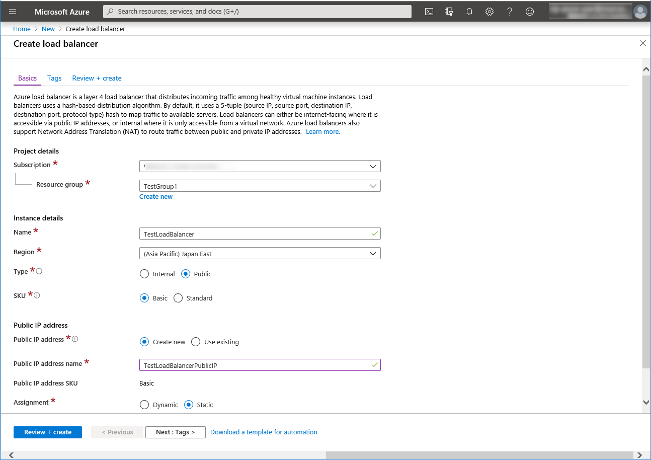
Configuring a load balancer
Log in to the Microsoft Azure portal (https://portal.azure.com/) and add a load balancer following the steps below.For details, see the following websites:
Select the Create a resource icon on the upper part of the window.
Select Networking and then Load Balancer.
The Create load balancer blade is displayed. Specify Name. Select Public for Type and Basic for SKU, respectively.
Specify Create new, Public IP address Name and Assignment for Public IP address.
Specify Subscription, Resource group, and Region, and click Review+create. Then click Create. Deploying the load balancer starts. This processing takes several minutes.
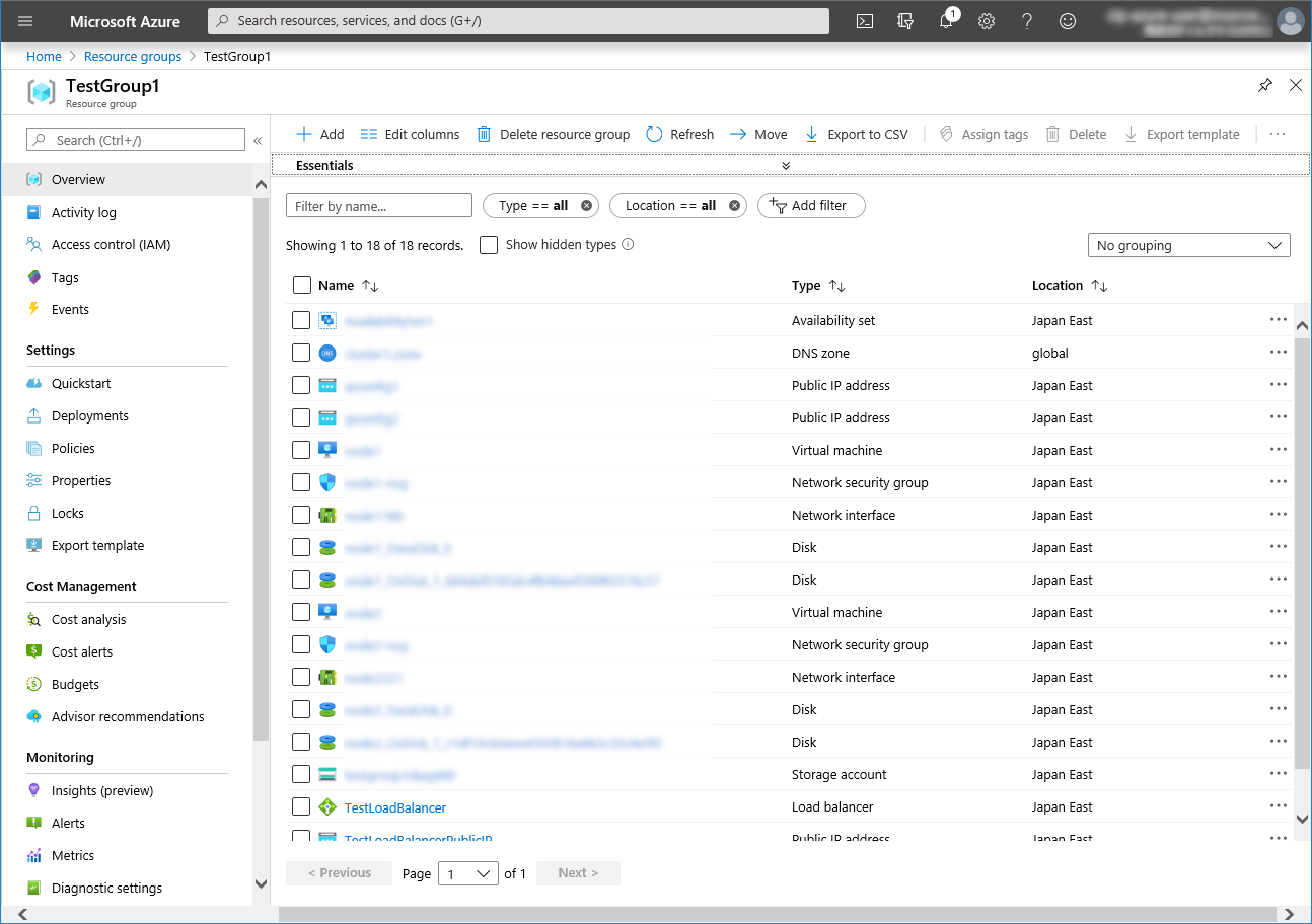
Configuring a load balancer (configuring a backend pool)
Associate a virtual machine registered to the availability set to the load balancer. After the load balancer has been deployed, select the Resource groups icon on the upper part of the window.
Select the resource group to which the created load balancer belongs from the resource group list.
The summary of the selected resource group is displayed. Select the created load balancer from the item list.
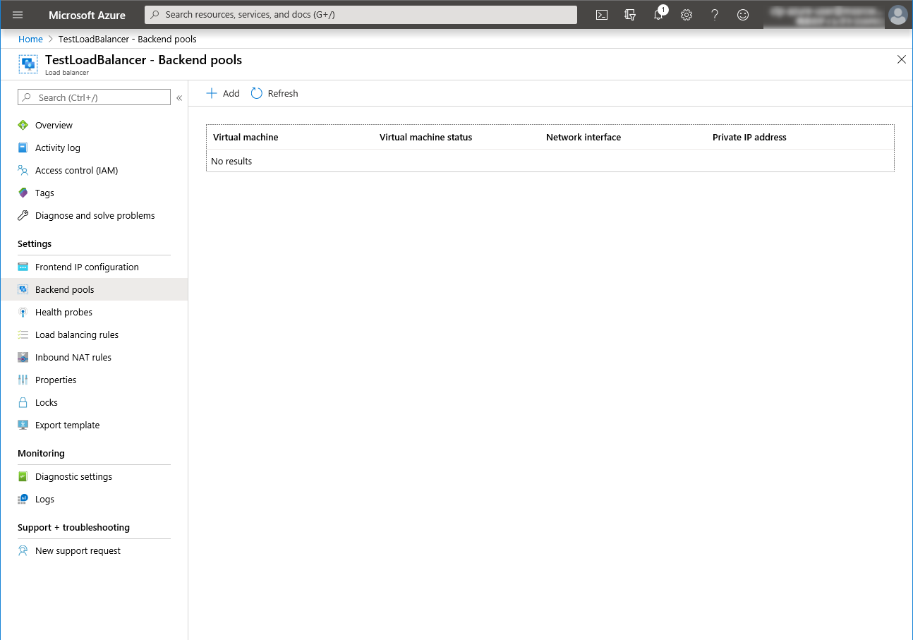
Select Backend pools.
Click Add.
Add backend pool is displayed. Specify Name.
Select Virtual machine for Associated to.
Specify Virtual machine and IP address for the virtual machine you want to associate. Repeat this procedure for the rest of such virtual machines.
Then click Add.

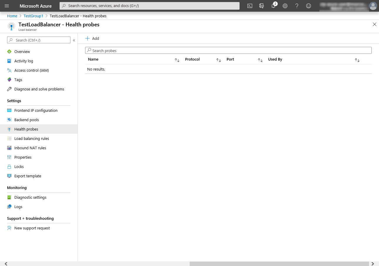
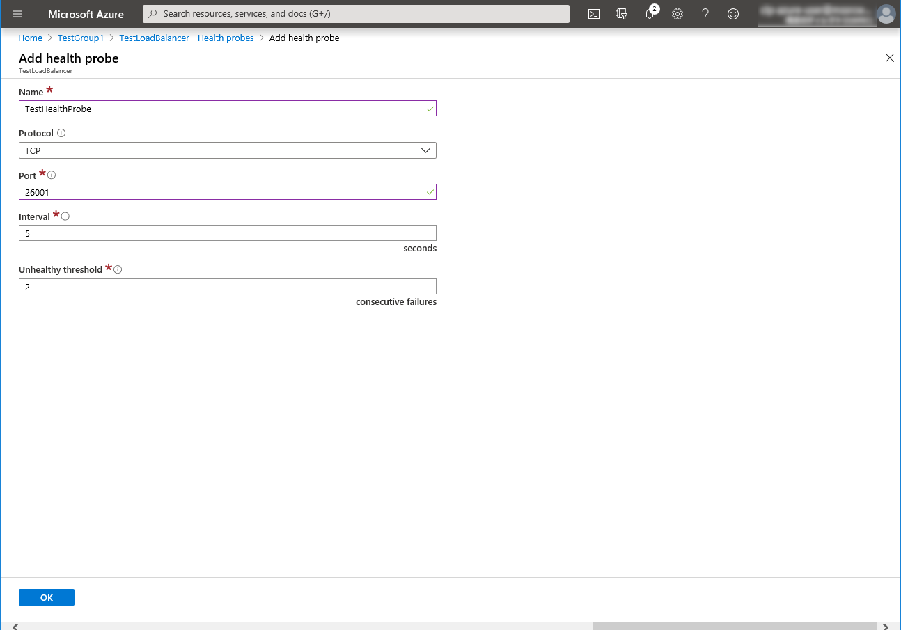
Configuring a load balancer (configuring a health probe)
Select Health probes.
Click Add.
Add health probe is displayed. Specify Name.
Specify Protocol and Port, and click OK.
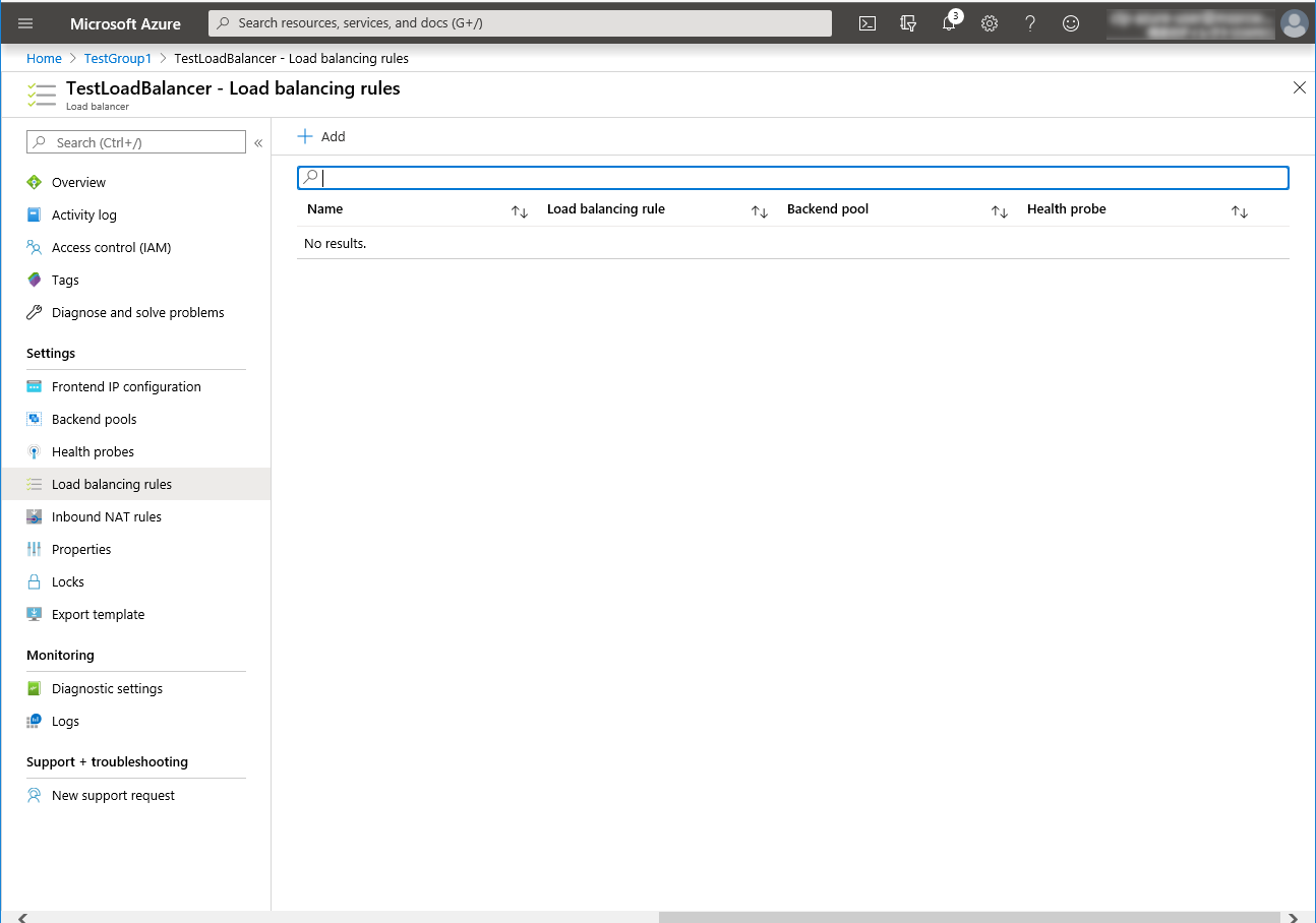
Configuring a load balancer (setting the load balancing rules)
Select Load balancing rules.
Click Add.
The Add load balancing rule blade is displayed. Specify Name.
Specify Port and Backend port, and click OK.
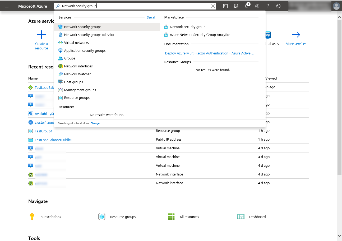
Setting the inbound security rules
Log in to the Microsoft Azure portal (https://portal.azure.com/) and set the inbound security rules following the steps below.
Search for Network security group.
Select Network security groups.
From the network security group list, select node1-nsg for node1 or node2-nsg for node2.
The summary is displayed.
Select Inbound security rules.
Click Add.
The Add inbound security rule blade is displayed. Specify Name.
Specify Destination port range and Protocol, and click Add.
Then, check <Load_balancer_frontend_IP(public_IP_address)> specified in the script before recovery action of the multi target monitor resource that is set in "3. Adding a monitor resource". Write down the confirmatory result.
Select the Resource groups icon on the upper part of the window.
Select the resource group to which the created load balancer belongs from the resource group list.
The summary of the selected resource group is displayed. Select the created load balancer from the item list.
The summary of the load balancer is displayed. Select Public IP address from the item list.


Adjusting the OS startup time, checking the network setting, checking the root file system, checking the firewall setting, synchronizing the server time, and checking the SELinux setting.
For each procedure, see "Settings after configuring hardware" in "Determining a system configuration" in the Installation and Configuration Guide.
Installing EXPRESSCLUSTER
For the installation procedure, see the Installation and Configuration Guide.After installation is complete, restart the OS.
Registering the EXPRESSCLUSER license
For the license registration procedure, see the Installation and Configuration Guide.
5.3. Configuring the EXPRESSCLUSTER settings
For the Cluster WebUI setup and connection procedures, see "Creating the cluster configuration data" in the Installation and Configuration Guide.
This section describes the procedure to add the following resources and monitor resources:
Mirror disk resource
Azure probe port resource
Azure probe port monitor resource
Azure load balance monitor resource
Custom monitor resource (for NP resolution)
IP monitor resource (for NP resolution)
Multi target monitor resource (for NP resolution)
For the settings of other resources and monitor resources, see the Installation and Configuration Guide and the Reference Guide.
Creating a cluster
Start the Cluster generation wizard to create a cluster.
Creating a cluster
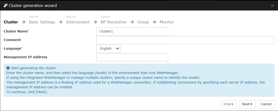
Access Cluster WebUI, and click Cluster generation wizard.
Cluster of Cluster generation wizard is displayed.
Enter a desired name in Cluster Name.Select an appropriate language in Language. Click Next.
Adding a group resource
Defining a group
Create a failover group.
The Group List window s displayed.
Click Add.
The Group Definition window is displayed.
Specify a failover group name (failover1) for Name. Click Next.
Mirror disk resource
Create a mirror disk resource. For details, see Understanding Mirror disk resources in "Group resource details" in the Reference Guide.
Click Add on the Group Resource List page.
Azure probe port resource
When EXPRESSCLUSTER is used on Microsoft Azure, EXPRESSCLUSTER provides a mechanism to wait for alive monitoring from a load balancer on a port specific to a node in which operations are running. For details about the Azure probe port resources", see "Understanding Azure probe port resources" in "Group resource details" in the Reference Guide.
Click Add on the Group Resource List page.
The Resource Definition of Group | failover1 window is displayed. Select the group resource type (Azure probe port resource) from the Type box and enter the group name (azurepp1) in the Name box. Click Next.
The Dependency window is displayed. Click Next without specifying anything.
The Recovery Operation window is displayed. Click Next.
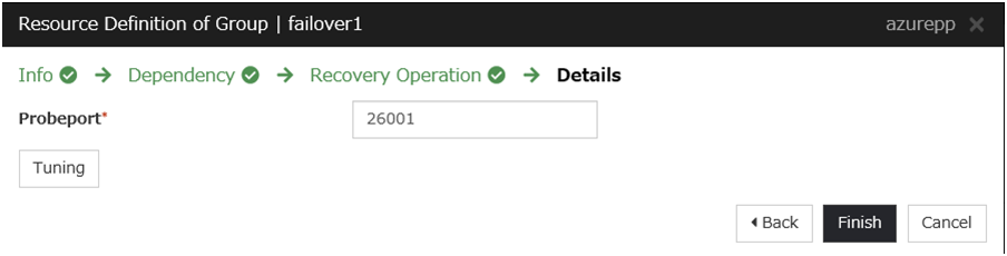
For Probeport, enter the value specified for Port when configuring a load balancer (configuring health probe).
Click Finish.
Adding a monitor resource
Azure probe port monitor resource
The port monitoring mechanism for alive monitoring is provided for the node in which the Microsoft Azure probe port resource is running. For details about the Azure probe port monitor resource, see "Understanding Azure probe port monitor resources" in the Reference Guide. Adding one Azure probe port monitor resource creates one Azure probe port monitor resource automatically.
Azure load balance monitor resource
The mechanism to monitor whether the port with the same port number as the probe port is open or not is provided for the node in which the Microsoft Azure probe port resource is not running. For details about the Azure load balance resource, see "Understanding Azure load balance monitor resources" in the Reference Guide. Adding one Azure probe port resource creates one Azure load balance monitor resource automatically.
Custom monitor resource
Sets a script to monitor whether communication with Microsoft Azure Service Management API is possible, and also monitors health of communication with an external network. For details about the custom monitor resource, see "Understanding custom monitor resources" in the Reference Guide.
Click Add on the Monitor Resource List page.
Select the monitor resource type (Custom monitor) from the Type box and enter the monitor resource name (genw1) in the Name box. Click Next.
Click Finish to finish setting.
IP monitor resource
Creates an IP monitor resource to monitor communication between clusters that are configured with virtual machines, and also to monitor whether communication with an internal network is health. For details about the IP monitor resource, see Understanding IP monitor resources in the Reference Guide.
Click Add on the Monitor Resource List page.
Select the monitor resource type (IP monitor) from the Type box and enter the monitor resource name (ipw1) in the Name box. Click Next.
Select one available server for Choose servers that execute monitoring.
Click Next.
The Monitor (special) window is displayed.
On the Common tab, select Add of IP Address and set an IP address of a server other than the server selected in step 3. Click Next.
Click Finish to finish setting.
Then, create a monitor resource on the other server. Click Add on the Monitor Resource List page.
Select the monitor resource type (ip monitor) from the Type box and enter the monitor resource name (ipw2) in the Name box. Click Next.
Click Finish to finish setting.
Multi target monitor resource
Creates a multi target monitor resource to check the statuses of the custom monitor resource and IP monitor resource. The custom monitor resource monitors communication to Microsoft Azure Service Management API. The IP monitor resource monitors communication between clusters that are configured with virtual machines. If their statuses are abnormal, execute the script in which the processing for NP resolution is described. For details about the multi target monitor resource, see Understanding multi target monitor resources in the Reference Guide.
Click Add on the Monitor Resource List page.
Select the monitor resource type (Multi target monitor) from the Type box and enter the monitor resource name (mtw1) in the Name box. Click Next.
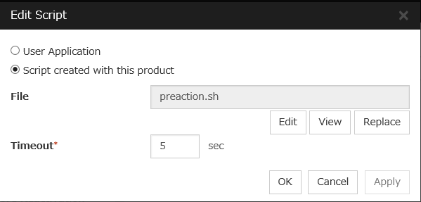
#! /bin/sh
<EXPRESSCLUSTER_installation_path>/bin/clpazure_port_checker -h 127.0.0.1 -p <Backend_port_of_the_load_balancer_of_Load_balancing_rule>
if [ $? -ne 0 ]
then
    clpdown
    exit 0
fi
<EXPRESSCLUSTER_installation_path>/bin/clpazure_port_checker -h <Frontend_IP(public_IP_address)_of_the_load_balancer> -p <Port_of_the_load_balancer_of_Load_balancing_rule>
if [ $? -ne 0 ]
then
    clpdown
    exit 0
fi
For Timeout, specify a value larger than the timeout value of clpazure_port_checker (fixed to five seconds). In the case of the above sample script, it is recommended to set a value larger than 10 seconds in order to execute clpazure_port_checker twice.Click OK.
Click Finish to finish setting.

Setting the cluster properties
For details about the cluster properties, see "Cluster properties" in the Reference Guide.
Cluster properties
Configure the settings in Cluster Properties to link Microsoft Azure and EXPERSSCLUSTER.
Enter Config Mode from Cluster WebUI, click the property icon of the cluster name.
Select the Timeout tab. For Timeout of Heartbeat, specify a value calculated by "A+B+C" as described below.
A: Interval of the monitor resource being monitored by the multi target monitor resource for NP resolution x (Retry Count+1)
* Among three monitor resources, select the monitor resource whose calculation result is the largest.
B: Interval of the multi target monitor resource x (Retry Count+1)
C: 30 seconds (Waiting time for heartbeat not to time out before the multi target monitor resource detects an error. The time can be changed accordingly.
Note
If Timeout of Heartbeat is shorter than the time that the multi target monitor resource requires to detect an error, a heartbeat timeout will be detected before starting the NP resolution processing. In this case, the same service may start doubly in the cluster because the service also starts on the standby server.
Click OK.
Applying the settings and starting the cluster
Select the Operation Mode on the drop down menu of the toolbar in Cluster WebUI to switch to the operation mode.
The procedure depends on the resource used. For details, refer to the following:Installation and Configuration Guide -> How to create a cluster
5.4. Verifying the created environment
Verify whether the created environment works properly by generating a monitoring error to fail over a failover group. If the cluster is running normally, the verification procedure is as follows:
Start the failover group (failover1) on the active node (node1). In the Status tab on the Cluster WebUI, confirm that Group Status of failover1 of node1 is Normal.
Change Operation Mode to Verification Mode from the Cluster WebUI pull-down menu.
In the Status tab on the Cluster WebUI, click the Enable dummy failure icon of azureppw1 of Monitors.
After the Azure probe port resource (azurepp1) activated three times, the failover group (failover1) becomes abnormal and fails over to node2. In the Status tab on the Cluster WebUI, confirm that Group Status of failover1 of node2 is Normal.
Also, confirm that access to the frontend IP and port of the Azure load balancer is normal after the failover.
Verifying the failover operation in case of a dummy failure is now complete. Verify the operations in case of other failures if necessary.
6. Cluster Creation Procedure (for an HA Cluster Using an Internal Load Balancer)
6.1. Creation example
This guide introduces the procedure for creating a 2-node unidirectional standby cluster using EXPRESSCLUSTER. This procedure is intended to create a mirror disk type configuration in which node1 is used as an active server.
The following tables describe the parameters that do not have a default value and the parameters whose values are to be changed from the default values.
Microsoft Azure settings (common to node1 and node2)
Setting item
Setting value
Resource group setting
Resource group
TestGroup1
Region
(Asia Pacific) Japan East
Virtual network setting
Name
Vnet1
Address space
10.5.0.0/24
Subnet Name
Vnet1-1
Subnet Address range
10.5.0.0/24
Resource group
TestGroup1
Location
(Asia Pacific) Japan East
Load balancer setting
Name
TestLoadBalancer
Type
Internal
Virtual network
Vnet1
Subnet
Vnet1-1
IP address assignment
Static
Private IP address
10.5.0.200
Resource group
TestGroup1
Region
(Asia Pacific) Japan East
Backend pool: Name
TestBackendPool
Associated to
Availability set
Target virtual machine
node1node2Network IP configuration
10.5.0.11010.5.0.111Health probe: Name
TestHealthProbe
Health probe: Port
26001
Load balancing rule: Name
TestLoadBalancingRule
Load balancing rule: Port
80 (Port number offering the operation)
Load balancing rule: Backend port
8080 (Port number offering the operation)
Microsoft Azure settings (specific to each of node1 and node2)
Setting item
Setting value
node1
node2
Virtual machine setting
Disk type
Standard HDD
User name
testlogin
Password
PassWord_123
Resource group
TestGroup1
Region
(Asia Pacific) Japan East
Network security group setting
Name
node1-nsg
node2-nsg
Availability set setting
Name
AvailabilitySet1
Update domains
5
Fault domains
2
Diagnostics storage account setting
Name
Automatically generated
Performance
Standard
Replication
Locally-redundant storage (LRS)
IP configuration setting
IP address
10.5.0.110
10.5.0.111
Disk setting
Name
node1_DataDisk_0
node2_DataDisk_0
Source type
None (empty disk)
Account type
Standard HDD
Size
20
EXPRESSCLUSTER settings (cluster properties)
Setting item
Setting value
node1
node2
Cluster Name
Cluster1
Server Name
node1
node2
NP Resolution Tab: Type
Ping
NP Resolution Tab: Ping Target
10.5.0.5
NP Resolution Tab: <server> column
Use
Use
EXPRESSCLUSTER settings (failover group)
Resource name
Setting item
Setting value
Mirror disk resource
Name
md
Details Tab: Mount Point
/mnt/md
Details Tab: Data Partition Device Name
/dev/sdc2
Details Tab: Cluster Partition Device Name
/dev/sdc1
Details Tab: File System
ext4
Mirror Tab: Execute the initial mirror construction
On
Mirror Tab: Execute initial mkfs
On
Azure probe port resource
Name
azurepp1
Probe port
26001 (Value specified for Port of Health probe)
EXPRESSCLUSTER settings (monitor resource)
Monitor resource name
Setting item
Setting value
Mirror disk monitor resource
Name
mdw1
Azure probe port monitor resource
Name
azureppw1
Recovery Target
azurepp1
Azure load balance monitor resource
Name
aurelbw1
Recovery Target
azurepp1
6.2. Configuring Microsoft Azure
Creating a resource group
Log in to the Microsoft Azure portal (https://portal.azure.com/) and create a resource group following the steps below.
Select the Resource groups icon on the upper part of the window. If there are existing resource groups, they are displayed in a list.
Select +Add at the upper part of the window.
Specify Subscription, Resource group, and Region, and click Review+Create.
Creating a virtual network
Log in to the Microsoft Azure portal (https://portal.azure.com/) and create a virtual network following the steps below.
Select the Create a resource icon on the upper partof the window.
Select Networking and then Virtual network.
Specify Name, Address space, Subscription, Resource group, Location, Name of Subnet, and Address range of Subnet, and click Create.
Creating a virtual machine
Log in to the Microsoft Azure portal (https://portal.azure.com/) and create virtual machines and disks following the steps below.Create as many virtual machines as required to create a cluster. Create node1 and then node2.
Select the Create a resource icon on the upper part of the window.
Select Compute and then See all.
Select CentOS-based 7.6.
Click Create.
Click Next: Tags >.
Click Next: Review + create >
The Review + create tab appears. Check the contents. If there is no problem, click Create. The deployment starts and takes several minutes.
Setting a private IP address
Log in to the Microsoft Azure portal (https://portal.azure.com/) and change the private IP address setting following the steps below. Since an IP address is initially set to be assigned dynamically, change the setting so that an IP address is assigned statically. Change the settings of node1 and then node2.
Select the Resource groups icon on the upper part of the window.
Select TestGroup1 from the resource group list.
The summary of TestGroup1 is displayed. Select virtual machine node1 or node2 from the item list.
Select Networking.
Select a network interface displayed in the list. The network interface name is generated automatically.
Select IP configurations.
Only ipconfig1 is displayed in the list. Select it.
Select Static for Assignment under Private IP address settings. Enter the IP address to be assigned statically in the IP address text box and click Save at the top of the window. The IP address of node1 is 10.5.0.110. The IP address of node2 is 10.5.0.111.
The virtual machines restart automatically so that new private IP addresses can be used.
Configuring virtual machines
Log in to the created node1 and node2 and specify the settings following the procedure below.Set a partition for the mirror disk resource. Create a file system in the added disk.Secure an area in the added disk by using the fdisk command and then create a file system.For details about the partition for the mirror disk resource, see "Settings after configuring hardware" in "Partition settings for Mirror disk resource (when using Replicator)" in "Determining a system configuration" in the Installation and Configuration Guide
Check the partition list. In the following example, the last line shows the added disk.
$ cat /proc/partitions
major minor  #blocks  name

   2        0          4 fd0
   8        0   31457280 sda
   8        1     512000 sda1
   8        2   30944256 sda2
   8       16   73400320 sdb
   8       17   73398272 sdb1
   8       32   20971520 sdc
Create a cluster partition and data partition in the added disk by using the fdisk command. Allocate 1 GB (1*1024*1024*1024 bytes) or more to a cluster partition. (If the size is specified as just 1 GB, the actual size will be larger than 1 GB depending on the disk geometry difference. This is not a problem.) Also, do not create a file system in a cluster partition.
If you select Execute initial mkfs when creating the cluster configuration data by using Cluster WebUI, EXPRESSCLUSTER creates a file system automatically. Note that existing data in the partition will be lost.
Configuring a load balancer
Log in to the Microsoft Azure portal (https://portal.azure.com/) and add an internal load balancer following the steps below. For details, see the following websites:
Select the Create a resource icon on the upper part of the window.
Select Networking and then Load balancer.
The Create load balancer blade is displayed. Specify Name. Select Internal for Type and Basic for SKU, respectively.
For Virtual network and Subnet, select the virtual network and subnet created in "2) Creating a virtual network."
Specify Subscription, Resource group, and Region, and click Review+create. Then click Create. Deploying the load balancer starts. This processing takes several minutes.
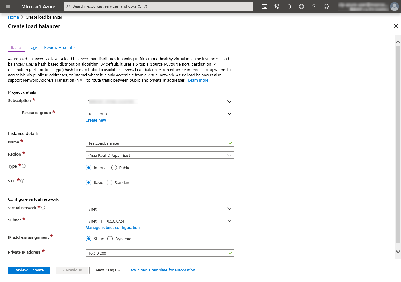
Configuring a load balancer (configuring a backend pool)
Associate a virtual machine registered to the availability set to the load balancer. After the load balancer has been deployed, select the Resource groups icon on the upper part of the window.
Select the resource group to which the created load balancer belongs from the resource group list.
The summary of the selected resource group is displayed. Select the created load balancer from the item list.
Select Backend pools.
Click Add.
Add backend pool is displayed. Specify Name.
Select Virtual machine for Associated to.
Specify Virtual machine and IP address for the virtual machine you want to associate. Repeat this procedure for the rest of such virtual machines.
Then click Add.
Configuring a load balancer (configuring a health probe)
Select Health probes.
Click Add.
Add health probe is displayed. Specify Name.
Specify Protocol and Port, and click OK.
Configuring a load balancer (setting the load balancing rules)
Select Load balancing rules.
Click Add.
The Add load balancing rule blade is displayed. Specify Name.
Specify Port and Backend port, and click OK.
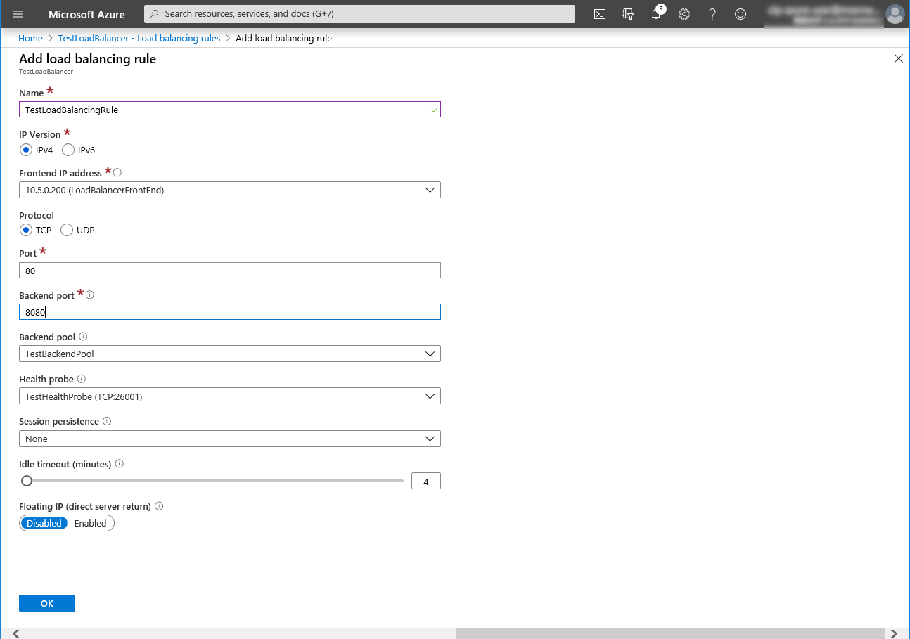
Adjusting the OS startup time, checking the network setting, checking the root file system, checking the firewall setting, synchronizing the server time, and checking the SELinux setting.
For each procedure, see "Settings after configuring hardware" in "Determining a system configuration" in the Installation and Configuration Guide.
Installing EXPRESSCLUSTER
For the installation procedure, see the Installation and Configuration Guide.After installation is complete, restart the OS.
Registering the EXPRESSCLUSER license
For the license registration procedure, see the Installation and Configuration Guide.
6.3. Configuring the EXPRESSCLUSTER settings
For the Cluster WebUI setup and connection procedures, see "Creating the cluster configuration data" in the Installation and Configuration Guide.
This section describes the procedure to add the following resources and monitor resources:
Mirror disk resource
Azure probe port resource
Azure probe port monitor resource
Azure load balance monitor resource
PING network partition resolution resource (for NP resolution)
For the settings of other resources and monitor resources, see the Installation and Configuration Guide and the Reference Guide.
Creating a cluster
Start the Cluster generation wizard to create a cluster.
Creating a cluster
Access Cluster WebUI, and click Cluster generation wizard.
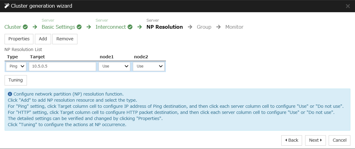
Adding a group resource
Defining a group
Create a failover group.
The Group List window s displayed.
Click Add.
Mirror disk resource
Create a mirror disk resource.For details, see Understanding Mirror disk resources in "Group resource details" in the Reference Guide.
Click Add on the Group Resource List page.
Azure probe port resource
When EXPRESSCLUSTER is used on Microsoft Azure, EXPRESSCLUSTER provides a mechanism to wait for alive monitoring from a load balancer on a port specific to a node in which operations are running.
For details about the Azure probe port resources", see "Understanding Azure probe port resources" in the Reference Guide.
Click Add on the Group Resource List page.
The Resource Definition of Group | failover1 window is displayed. Select the group resource type (Azure probe port resource) from the Type box and enter the group name (azurepp1) in the Name box. Click Next.
The Dependency window is displayed. Click Next without specifying anything.
The Recovery Operation window displayed. Click Next.
For Probeport, enter the value specified for Port when configuring a load balancer (configuring health probe).
Click Finish.
Adding a monitor resource
Azure probe port monitor resource
The port monitoring mechanism for alive monitoring is provided for the node in which the Microsoft Azure probe port resource is running.For details about the Azure probe port resources", see "Understanding Azure probe port resources" in the Reference Guide.Adding one Azure probe port monitor resource creates one Azure probe port monitor resource automatically.Azure load balance monitor resource
The mechanism to monitor whether the port with the same port number as the probe port is open or not is provided for the node in which the Microsoft Azure probe port resource is not running.For details about the Azure load balance resource, see "Understanding Azure load balance monitor resources" in the Reference Guide.Adding one Azure probe port resource creates one Azure load balance monitor resource automatically.
Applying the settings and starting the cluster
Select the Operation Mode on the drop down menu of the toolbar in Cluster WebUI to switch to the operation mode.
The procedure depends on the resource used. For details, refer to the following:Installation and Configuration Guide -> How to create a cluster
6.4. Verifying the created environment
Verify whether the created environment works properly by generating a monitoring error to fail over a failover group.
If the cluster is running normally, the verification procedure is as follows:
Start the failover group (failover1) on the active node (node1). In the Status tab on the Cluster WebUI, confirm that Group Status of failover1 of node1 is Normal.
Change Operation Mode to Verification Mode from the WebManager pull-down menu.
In the Status tab on the Cluster WebUI, click the Enable dummy failure icon of azureppw1 of Monitors.
- When the time specified for Interval elapses, the failover group (failover1) enters an error status and fails over to node2. In the Status tab on the Cluster WebUI, confirm that Group Status of failover1 of node2 is Normal.Also, confirm that access to the frontend IP and port of the Azure load balancer is normal after the failover.
Verifying the failover operation in case of a dummy failure is now complete. Verify the operations in case of other failures if necessary.
7. Error Messages
For the error messages related to resources and monitor resources, see the following:
"Error messages" in the Reference Guide.
8. Notes and Restrictions
8.1. HA cluster using Azure DNS
8.1.1. Notes on Microsoft Azure
There is a tendency for the performance difference (performance deterioration rate) to increase in a multi-tenant cloud environment compared to a physical environment or general virtualization environment (non-cloud environment). Therefore, pay careful attention to this point when designing a performance-oriented system.
Even if a virtual machine is just shut down, its status is Stopped and billing continues. Execute Stop on the virtual machine setting window of the Microsoft Azure portal to change the virtual machine state to Stopped (Deallocated).
An availability set can be set only when creating a virtual machine. To move a virtual machine to and from the availability set, it is necessary to create an availability set again.
To set up EXPRESSCLUSTER to work with Microsoft Azure, a Microsoft Azure organizational account is required. An account other than the organizational account cannot be used because an interactive login is required when executing the Azure CLI.
8.1.2. Notes on EXPRESSCLUSTER
Please refer the following for notes for EXPRESSCLUSTER on Azure:
EXPRESSCLUSTER X Getting Started Guide
"Communication port number" in "Notes and Restrictions"
"Azure DNS resources" in "Notes and Restrictions"
"Setting up Azure DNS resources" in "8. Notes and Restrictions"
EXPRESSCLUSTER X Reference Guide
"Notes on Azure DNS resources"
"Notes on Azure DNS monitor resources"
Therefore, it is recommended to set Heartbeat Timeout parameter on Timeout tab in Cluster Properties more than 30 sec.
In addition to Heartbeat Timeout, please also note the following.
Please set Heartbeat Timeout parameter less than OS reboot time.
When changing Shutdown Monitor Timeout parameter on Monitor tab in Cluster Properties from the default value (Use Heartbeat Timeout), please set the parameter less than Heartbeat Timeout.
Please refer the following about the above:
EXPRESSCLUSTER X Getting Started Guide
"Adjusting OS startup time" in "Notes and Restrictions"
EXPRESSCLUSTER X Reference Guide
"Timeout tab"
"Monitor tab"
8.2. HA cluster using a load balancer
8.2.1. Notes on Microsoft Azure
There is a tendency for the performance difference (performance deterioration rate) to increase in a multi-tenant cloud environment compared to a physical environment or general virtualization environment (non-cloud environment). Therefore, pay careful attention to this point when designing a performance-oriented system.
Even if a virtual machine is just shut down, its status is Stopped and billing continues. Execute Stop on the virtual machine setting window of the Microsoft Azure portal to change the virtual machine state to Stopped (Deallocated).
An availability set can be set only when creating a virtual machine. To move a virtual machine to and from the availability set, it is necessary to create an availability set again.
8.2.2. Notes on EXPRESSCLUSTER
Please refer the following for notes for EXPRESSCLUSTER on Azure:
EXPRESSCLUSTER X Getting Started Guide
"Communication port number" in "Notes and Restrictions"
"Setting up Azure probe port resources" in "8. Notes and Restrictions"
"Setting up Azure load balance monitor resources" in "Notes and Restrictions"
EXPRESSCLUSTER X Reference Guide
"Notes on Azure probe port resources"
"Notes on Azure probe port monitor resources"
"Note on Azure load balance monitor resources"
Therefore, it is recommended to set Heartbeat Timeout parameter on Timeout tab in Cluster Properties more than 30 sec.
In addition to Heartbeat Timeout, please also note the following.
Please set Heartbeat Timeout parameter less than OS reboot time.
When changing Shutdown Monitor Timeout parameter on Monitor tab in Cluster Properties from the default value (Use Heartbeat Timeout), please set the parameter less than Heartbeat Timeout.
Please refer the following about the above:
EXPRESSCLUSTER X Getting Started Guide
"Adjusting OS startup time" in "Notes and Restrictions"
EXPRESSCLUSTER X Reference Guide
"Timeout tab"
"Monitor tab"