1. Preface
1.1. Who Should Use This Guide
The Installation and Configuration Guide is intended for system engineers and administrators who want to build, operate, and maintain a cluster system. Instructions for designing, installing, and configuring a cluster system with EXPRESSCLUSTER are covered in this guide.
1.2. How This Guide is Organized
2. Determining a system configuration: Provides instructions for how to verify system requirements and determine the system configuration.
3. Configuring a cluster system: Helps you understand how to configure a cluster system.
4. Installing EXPRESSCLUSTER: Provides instructions for how to install EXPRESSCLUSTER.
5. Registering the license: Provides instructions for how to register the license.
6. Creating the cluster configuration data: Provides instructions for how to create the cluster configuration data with the Cluster WebUI.
7. Verifying a cluster system: Verify if the cluster system that you have configured operates successfully.
8. Modifying the cluster configuration data: Provides instructions for how to modify the cluster configuration data.
9. Verifying operation: Run the pseudo-failure test and adjust the parameters.
10. Preparing to operate a cluster system: Provides information on what you need to consider before actually start operating EXPRESSCLUSTER.
11. Uninstalling and reinstalling EXPRESSCLUSTER: Provides instructions for how to uninstall and reinstall EXPRESSCLUSTER.
12. Troubleshooting: Describes problems you might experience when installing or setting up EXPRESSCLUSTER X SingleServerSafe and how to resolve them.
1.3. EXPRESSCLUSTER X Documentation Set
The EXPRESSCLUSTER X manuals consist of the following six guides. The title and purpose of each guide is described below:
EXPRESSCLUSTER X Getting Started Guide
This guide is intended for all users. The guide covers topics such as product overview, system requirements, and known problems.
EXPRESSCLUSTER X Installation and Configuration Guide
This guide is intended for system engineers and administrators who want to build, operate, and maintain a cluster system. Instructions for designing, installing, and configuring a cluster system with EXPRESSCLUSTER are covered in this guide.
EXPRESSCLUSTER X Reference Guide
This guide is intended for system administrators. The guide covers topics such as how to operate EXPRESSCLUSTER, function of each moduleand troubleshooting. The guide is supplement to the Installation and Configuration Guide.
EXPRESSCLUSTER X Maintenance Guide
This guide is intended for administrators and for system administrators who want to build, operate, and maintain EXPRESSCLUSTER-based cluster systems. The guide describes maintenance-related topics for EXPRESSCLUSTER.
EXPRESSCLUSTER X Hardware Feature Guide
This guide is intended for administrators and for system engineers who want to build EXPRESSCLUSTER-based cluster systems. The guide describes features to work with specific hardware, serving as a supplement to the Installation and Configuration Guide.
EXPRESSCLUSTER X Legacy Feature Guide
This guide is intended for administrators and for system engineers who want to build EXPRESSCLUSTER-based cluster systems. The guide describes EXPRESSCLUSTER X 4.0 WebManager and Builder.
1.4. Conventions
In this guide, Note, Important, See also are used as follows:
Note
Used when the information given is important, but not related to the data loss and damage to the system and machine.
Important
Used when the information given is necessary to avoid the data loss and damage to the system and machine.
See also
Used to describe the location of the information given at the reference destination.
The following conventions are used in this guide.
Convention |
Usage |
Example |
|---|---|---|
Bold
|
Indicates graphical objects, such as fields, list boxes, menu selections, buttons, labels, icons, etc.
|
In User Name, type your name.
On the File menu, click Open Database.
|
Angled bracket within the command line |
Indicates that the value specified inside of the angled bracket can be omitted. |
clpstat -s[-h host_name] |
# |
Prompt to indicate that a Linux user has logged on as root user. |
# clpcl -s -a |
Monospace (courier) |
Indicates path names, commands, system output (message, prompt, etc.), directory, file names, functions and parameters. |
|
Monospace bold (courier)
|
Indicates the value that a user actually enters from a command line.
|
Enter the following:
# clpcl -s -a
|
Monospace italic
(courier)
|
Indicates that users should replace italicized part with values that they are actually working with.
|
rpm -i expresscls-<version_number>-<release_number>.x86_64.rpm
|
1.5. Contacting NEC
For the latest product information, visit our website below:
2. Determining a system configuration
This chapter provides instructions for determining the cluster system configuration that uses EXPRESSCLUSTER.
This chapter covers:
2.1. Steps from configuring a cluster system to installing EXPRESSCLUSTER
2.4. Checking system requirements for each EXPRESSCLUSTER module
2.5. Example of EXPRESSCLUSTER (main module) hardware configuration
2.1. Steps from configuring a cluster system to installing EXPRESSCLUSTER
Before you set up a cluster system that uses EXPRESSCLUSTER, you should carefully plan the cluster system with due consideration for factors such as hardware requirements, software to be used, and the way the system is used. When you have built the cluster, check to see if the cluster system is successfully set up before you start its operation.
This guide explains how to create a cluster system with EXPRESSCLUSTER through step-by-step instructions. Read each chapter by actually executing the procedures to install the cluster system. Following is the steps to take from designing the cluster system to operating EXPRESSCLUSTER:
The following is the procedure for configuring a cluster system to run an operation test:
Prepare for installing EXPRESSCLUSTER. Determine the hardware configuration and the setting information of a cluster system to be constructed.
Step 1 "2. Determining a system configuration"
Step 2 "3. Configuring a cluster system"
Install EXPRESSCLUSTER to server machines, create a configuration data file on the Cluster WebUI by using the setting information created in Steps 1 and 2 , and construct a cluster. After that, verify that a cluster system operates normally.
Step 3 "4. Installing EXPRESSCLUSTER"
Step 4 "5. Registering the license"
Step 5 "6. Creating the cluster configuration data"
Step 6 "7. Verifying a cluster system"
Step 7 "8. Modifying the cluster configuration data"
Perform an evaluation required before starting the EXPRESSCLUSTER operation. Test the operations of a constructed cluster system, and then check what should be checked before starting the EXPRESSCLUSTER operation. On the last part of this section, how to uninstall and reinstall EXPRESSCLUSTER is described.
Step 8 "9. Verifying operation"
Step 9 "10. Preparing to operate a cluster system"
Step 10 "11. Uninstalling and reinstalling EXPRESSCLUSTER"
See also
Refer to the Reference Guide as you need when operating EXPRESSCLUSTER by following the procedures introduced in this guide. See the Getting Started Guide for installation requirements.
2.2. What is EXPRESSCLUSTER?
EXPRESSCLUSTER is software that enhances availability and expandability of systems by a redundant (clustered) system configuration. The application services running on the active server are automatically taken over to the standby server when an error occurs on the active server.

The following can be achieved by installing a cluster system that uses EXPRESSCLUSTER.
- High availabilityThe down time is minimized by automatically failing over the applications and services to a "healthy" server when one of the servers which configure a cluster stops.
- High expandabilityAn expandable database platform can be provided by supporting a parallel database up to 32 servers.
See also
For details on EXPRESSCLUSTER, refer to "What is a cluster system?" and "Using EXPRESSCLUSTER" in the Getting Started Guide.
2.2.1. EXPRESSCLUSTER modules
EXPRESSCLUSTER consists of following two modules:
- EXPRESSCLUSTER ServerThe main module of EXPRESSCLUSTER and has all high availability functions of the server. Install this module on each server constituting the cluster.
- Cluster WebUIThis is a tool to create the configuration data of EXPRESSCLUSTER and to manage EXPRESSCLUSTER operations. The Cluster WebUI is installed in EXPRESSCLUSTER Server, but it is distinguished from the EXPRESSCLUSTER Server because the Cluster WebUI is operated through a Web browser on the management PC.

2.3. Planning system configuration
You need to determine an appropriate hardware configuration to install a cluster system that uses EXPRESSCLUSTER. The configuration examples of EXPRESSCLUSTER are shown below.
See also
For latest information on system requirements, refer to the Getting Started Guide.
2.3.2. Example 1: configuration using a shared disk with two nodes
The most commonly used system configuration:
Different models can be used for servers.
Use LAN cables for interconnection. (A dedicated HUB can be used for connection as in the case with the 4-nodes configuration)
Connect COM (RS-232C) ports using a LAN cable.

2.3.3. Example 2: configuration using mirror disks with two nodes
Different models can be used for servers. However, servers should have the same architecture.
Use LAN cables for interconnection. Use cross cables for the interconnection between the mirror disks (mirror disk connect). Do not connect a HUB.
Connect COM (RS-232C) ports using LAN cables.

2.3.4. Example 3: configuration using mirror disks with two nodes and one LAN
Different models can be used for servers, but the servers must have the same architecture.

2.3.5. Example 4: configuration using mirror partitions on the disks for OS with two nodes
As shown below, a mirroring partition can be created on the disk used for the OS.

See also
For mirror partition settings, refer to "Group resource details" in the Reference Guide.
2.3.6. Example 5: configuration with three nodes
For three nodes configuration, prepare two mirror disks on a standby server where mirror resources are integrated (in the figure below, server3).
Install a dedicated HUB for LAN used for interconnect and mirror disk connection.
For the HUB, use the high-speed HUB.
It is not necessary to establish connectivity between servers using the connect COM (RS-232C).

2.3.7. Example 6: configuration with four nodes
As is the case with two nodes, connect a shared disk.
Install a dedicated HUB for interconnect.
It is not necessary to establish connectivity between servers using the connect COM (RS-232C).

2.3.8. Example 7: Configuration of hybrid type with three nodes
This is a configuration with three nodes, which consists of two nodes connected to the shared disk and one node with the disk to be mirrored.
Different models can be used for servers but the servers must be configured in the same architecture.
Install a dedicated HUB for interconnection and LAN of mirror disk connect.
For the HUB, use a fast HUB.

2.3.9. Example 8: Configuration for using BMC-related functions with two nodes
This is an example of 2-node cluster configuration for using the BMC linkage functions, such as the forced stop function of a physical machine, chassis identify function, BMC heartbeat resources, and external linkage monitor.
Different models of server can be used together, but each server must support the use of BMC linkage functions.
When using BMC-related functions other than BMC heartbeat resources, connect the interconnect LAN and BMC management LAN via a dedicated HUB.
Use as fast a HUB as is available.

2.4. Checking system requirements for each EXPRESSCLUSTER module
EXPRESSCLUSTER X consists of two modules: EXPRESSCLUSTER Server (main module)and Cluster WebUI. Check configuration and operation requirements of each machine where these modules will be used. For details about the operating environments, see "Installation requirements for EXPRESSCLUSTER" in the Getting Started Guide.
2.5. Example of EXPRESSCLUSTER (main module) hardware configuration
The EXPRESSCLUSTER Server is a core component of EXPRESSCLUSTER. Install it on each server that constitutes a cluster. Cluster WebUI is included in the EXPRESSCLUSTER Server and it is automatically installed once the EXPRESSCLUSTER Server is installed.
2.5.1. General requirements
Following is the recommended specification for the EXPRESSCLUSTER Server:
RS-232C port: 1 port (not necessary when configuring a cluster with more than 3 nodes)
Ethernet port: 2 or more ports
Shared disk (For disk resource and/or hybrid disk resource)
Disk for mirroring or free partition (For mirror disk resource or hybrid disk resource)
CD-ROM drive
See also
For information on system requirements for supported hardware and OS, refer to the Getting Started Guide.
2.6. Verifying system requirements for the Cluster WebUI
To monitor a cluster system that uses EXPRESSCLUSTER, use Cluster WebUI, which accesses from a management PC via a Web browser. Therefore, a management PC should be able to make access to the cluster via network. The management PC can be Linux or Windows.
For information of the latest system requirements of the Cluster WebUI (supported operating systems and browsers, required memory and disk size) see the Getting Started Guide.
2.7. Determining a hardware configuration
Determine a hardware configuration considering an application to be duplicated on a cluster system and how a cluster system is configured. Read "3. Configuring a cluster system" before you determine a hardware configuration.
2.8. Settings after configuring hardware
After you have determined the hardware configuration and installed the hardware, do the following:
2.8.1. Shared disk settings for disk resource (Required for disk resource)
2.8.2. Shared disk settings for Hybrid disk resource (Required for Replicator DR)
2.8.3. Partition settings for Hybrid disk resource (Required for the Replicator DR)
2.8.4. Partition settings for Mirror disk resource (when using Replicator)
2.8.5. Adjustment of the operating system startup time (Required)
2.8.3. Partition settings for Hybrid disk resource (Required for the Replicator DR)
Follow the steps below to configure the partitions when a non-shared disk (such as internal disk of the server or a non-shared external disk) is used as a hybrid disk resource.
For settings in a general mirror configuration (when Replicator is used), see "2.8.4. Partition settings for Mirror disk resource (when using Replicator)".
When a shared disk is used as a hybrid disk resource, refer to "2.8.2. Shared disk settings for Hybrid disk resource (Required for Replicator DR)".
Note
When you continue using an existing partition (in the cases such as clustering a single server) or reinstalling server, do not allocate a partition for a hybrid disk resource or create a file system. The data on the partition gets deleted if you allocate a partition for hybrid disk resources or create a file system.
- Allocate a cluster partition for hybrid disk resource.Allocate a partition to be used by the mirror driver. The mirror driver and mirror agent use this partition to monitor the status of hybrid disk resource. Create a partition in every server in the cluster that uses hybrid disk resource. Use the fdisk command to set 83 (Linux) for the partition ID.
Note
A cluster partition for hybrid disk resource should be 1024MB (1024*1024*1024 bytes) or larger. (The size will be actually larger than 1024MB even if you specify exactly 1024MB because of the disk geometry difference. This will cause no problem.) You do not need to create a file system on this partition.
Initialize the cluster partition. (Required only when you continue using a disk that is used as disk that was used as EXPRESSCLUSTER mirror disk or hybrid disk.)
Initialization is required because the old data on partitions survive even if allocation of partitions is performed.
If you continue to use a disk that was once used as an EXPRESSCLUSTER mirror disk or hybrid disk, make sure to initialize it.
Run the following command:
dd if=/dev/zero of=<Partition device name to be used as cluster partition>
Note
Running the dd command initializes the specified partition. Before you run the dd command make sure to check the partition device name.
Note
The following message is displayed when you run the dd command. This is not an error.
dd: writing to <Partition_device_name_used_as_a_cluster_partition>: No space left on device
- Allocate a partition for hybrid disk resource.Create a partition to be used for hybrid disk resource. Create the partition in every server in the cluster that use hybrid resource. Run the fdisk command to set 83 (Linux) for the partition ID.
- Create a file system.It is necessary to create a file system on the partition for hybrid disk resource.
The hybrid disk resource basically does not depend on file systems, problems may occur depending on the specification of the fsck of the file system.
It is recommended to use file systems which have journal function for fault tolerance improvement of the system.
Following is the currently supported file systems:
ext3
ext4
xfs
reiserfs
jfs
vxfs
It is also possible to directly access the partition without creating a file system.
Note
The EXPRESSCLUSTER controls the file systems on hybrid disk resource. Do not enter the hybrid disk resource or partition for hybrid disk resource into /etc/fstab in the operating system. (Do not enter them into /etc/fstab, even if the ignore option is specified.)
Note
Distributions and kernels where vxfs can be used depend on the support status of vxfs.
Note
When problems occur because of forgetting creating file system, execute the following steps:
- Stop cluster when the cluster is running.For the Cluster WebUI, select Service -> Stop Cluster.For the commands, use clpcl -t -a command.
- Stop mirror agent when mirror agent is running.For the Cluster WebUI, select Service -> Stop Mirror Agent.For the commands, run service clusterpro_md stop on each server.
- Lift access control to the hybrid disk partition.use the clproset command.(Example: cloproset -w -d <partition_device>)
- Create file systemsuse the mkfs or other commands.(Example: mkfs -t ext3 <partition_device>)
- Reboot the system.
Note
When creating an ext4 file system, specify the options as follows.For details, refer to the following topic in the "Getting Started Guide":<For RHEL7, Asianux Server 7, and Ubuntu>
mkfs -t ext4 -O -64bit,-uninit_bg <partition device>
<For other than RHEL7, Asianux Server 7, and Ubuntu>
mkfs -t ext4 -O -uninit_bg <partition device>
- Create a mount point.Create a directory to mount the partition for hybrid disk resource.
If a file system is not used for the partition for hybrid disk resources, a mount point does not need to be created.
2.8.4. Partition settings for Mirror disk resource (when using Replicator)
Set up partitions for mirror disk resource by following the steps below. For using hybrid disk resource (for Replicator DR), refer to "2.8.3. Partition settings for Hybrid disk resource (Required for the Replicator DR)".
Note
When you continue using an existing partition (in the cases such as clustering a single server) or reinstalling server, do not allocate a partition for mirror resources. If you create the partition for mirror resources, data on the existing partition will be deleted.
- Allocate a cluster partition.Allocate a partition to be used by the mirror driver. The mirror driver and mirror agent use this partition to monitor the status of mirror disk resource. Create a partition in every server in the cluster that uses mirror disk resource. Use the fdisk command to set 83 (Linux) for the partition ID.
Note
A cluster partition should be 1024MB (1024*1024*1024 bytes) or larger. (The size will be actually larger than 1024MB even if you specify exactly 1024MB because of the disk geometry difference. This will cause no problem.) You do not need to create a file system on this partition.
- Initialize the cluster partition. (Required only when you continue using a disk that is used as disk that was used as EXPRESSCLUSTER mirror disk or hybrid disk.)
Initialization is required because the old data on the cluster partition remains even if allocation of partitions is performed.
If you continue to use a disk that was once used as an EXPRESSCLUSTER mirror disk or hybrid disk, make sure to initialize it.
Run the following command:
dd if=/dev/zero of=<The name of the partition device to be used as cluster partition>
Note
Running the dd command initializes the specified partition. Before you run the dd command make sure to check the partition device name.
Note
The following message is displayed when you run the dd command. This is not an error.
dd: writing to <Partition_device_name_used_as_a_cluster_partition>: No space left on device
- Allocate a partition for mirror disk resourceCreate a partition to be used for mirror disk resource. Create a partition in every server in the cluster that use mirror resource. Run the fdisk command to set 83 (Linux) for the partition ID.
- Create a file system.Creation of a file system for the partition used for mirror resource depends on the Execute initial mkfs setting.
- If Execute initial mkfs is selected when creating the cluster configuration data using the Cluster WebUI, EXPRESSCLUSTER will automatically create a file system.Note that the existing data on the partition will be lost.
- If Execute initial mkfs is not selected when creating the cluster configuration data using the Cluster WebUI, EXPRESSCLUSTER will not create a file system.Because this option causes the existing file system on the partition to be used, it is necessary to create a file system in advance.
In addition, note the following about the partition for mirror resource:
The mirror resource basically does not depend on file systems, problems may occur depending on the specification of the fsck of the file system.
It is recommended to use a file system capable of journaling to avoid system failures.
The file systems currently supported are:
ext3
ext4
xfs
reiserfs
jfs
vxfs
It is also possible to directly access the partition without creating a file system.
Note
Do not select Execute initial mkfs when you use the data has been saved on the partition.If you select it, the data will be removed.Note
The EXPRESSCLUSTER controls the file systems on the mirror resource. Do not enter the mirror resource or a partition for the mirror resource into the operating system /etc/fstab directory. (Do not enter them into /etc/fstab, even if the ignore option is specified.)
Note
Distributions and kernels where vxfs can be used depend on the vxfs support status.
Note
When manually creating an ext4 file systm by using mkfs, specify the options as follows.
<For RHEL7, Asianux Server 7, and Ubuntu>
mkfs -t ext4 -O -64bit,-uninit_bg <partition device>
<For other than RHEL7, Asianux Server 7, and Ubuntu>
mkfs -t ext4 -O -uninit_bg <partition device>
For details, see the following topic in the Getting Started Guide: - Create a mount point.Create a directory to mount the partition for mirror resource.Create this directory on all servers in the cluster that use mirror resource.
2.8.5. Adjustment of the operating system startup time (Required)
It is necessary to configure the time from power-on of each node in the cluster to the server operating system startup to be longer than the following:
The time from power-on of the shared disk to the point they become available.
Heartbeat timeout time (90 seconds by default in the Cluster WebUI.)
Adjustment of the startup time is necessary due to the following reasons:
Activating disk resources fails if the cluster system is started by powering on the shared disk and servers.
A failover fails if a server, with data you want to fail over by rebooting the server, reboots within the heartbeat timeout. This is because a remote server assumes heartbeat is continued.
Consider the times durations above and adjust the operating system startup time by following the procedure below.
Note
How you configure the time is determined by what is used as an operating system loader, LILO or GRUB.
When GRUB is used for the operating system loader
- Edit /boot/grub/menu.lst.Specify the timeout <startup_time> (in seconds) option. In the following example, change only the underlined part.
Example: Startup time: 90 seconds
default 0
timeout 90
title linux
    kernel (hd0,1)/boot/vmlinuz
    root=/dev/sda2 vga=785
    initrd (hd0,1)/boot/initrd
When LILO is used for the operating system loader
- Edit /etc/lilo.conf.Specify the prompt option and timeout=<startup_time> (in 1/10 seconds) option, or specify the delay=<startup_time> (in 1/10 seconds) option without specifying the prompt option. In the following example, change only the underlined part.
Example 1: Output prompt. Startup time: 90 seconds
boot=/dev/sda
map=/boot/map
install=/boot/boot.b
prompt
linear
timeout=900
image=/boot/vmlinuz
    label=linux
    root=/dev/sda1
    initrd=/boot/initrd.img
    read-only
Example 2: Not output prompt. Startup time: 90 seconds
boot=/dev/sda
map=/boot/map
install=/boot/boot.b
#prompt
linear
delay=900
image=/boot/vmlinuz
    label=linux
    root=/dev/sda1
    initrd=/boot/initrd.img
    read-only
Run the /sbin/lilo command to make the changes of the setting effective.
Note
When you are using an operating system loader other than LILO or GRUB is used, see the setup guide of the operating system loader.
When GRUB2 is used for the operating system loader
- Edit /etc/default/grub.Specify GRUB_TIMEOUT=<startup_time> (in seconds).
Example: Startup time: 90 seconds
GRUB_TIMEOUT=90
Run the command to make the changes of the setting effective.
For the BIOS base server
# grub2-mkconfig -o /boot/grub2/grub.cfgFor the UEFI base server
# grub2-mkconfig -o /boot/efi/EFI/redhat/grub.cfg
2.8.6. Verification of the network settings (Required)
On all servers in the cluster, verify the status of the following networks using the ifconfig or ping command. Verify if network devices (eth0, eth1, eth2, etc) are assigned to appropriate roles, such as public LAN and interconnect-dedicated LAN.
Public LAN (used for communication with all the other machines)
LAN dedicated to interconnect (used for communication between EXPRESSCLUSTER Servers)
Host name
Note
It is not necessary to specify the IP addresses of floating IP resources or virtual IP resources used in the cluster in the operating system.
2.8.7. Verification of the root file system (Required)
It is recommended to use a file system which is capable of journaling for the root file system in the operating system. File systems such as ext3, ext4, JFS, ReiserFS, XFS are available for a journaling file system supported by Linux (version 2.6 or later).
Important
If a file system that is not capable of journaling is used, you must run an interactive command (fsck the root file system) when rebooting from server or OS stop (for example, normal shutdown could not be done.) This is not limited to cluster system and the same is true for a single server.
2.8.8. Verification of the firewall settings (Required)
EXPRESSCLUSTER uses several port numbers for communication between the modules. For details about the port numbers to be used, see "Before 4. Installing EXPRESSCLUSTER" of "Notes and Restrictions" in the "Getting Started Guide".
2.8.9. Server clock synchronization (Required)
It is recommended to regularly synchronize the clocks of all the servers in the cluster. Make the settings that synchronize server clocks through protocol such as ntp on a daily basis.
Note
If the clock in each server is not synchronized, it may take time to analyze the problem when an error occurs.
3. Configuring a cluster system
This chapter provides information on applications to be duplicated, cluster topology, and explanation on cluster configuration data that are required to configure a cluster system.
This chapter covers:
3.1. Configuring a cluster system
This chapter provides information necessary to configure a cluster system, including the following topics:
Determining a cluster system topology
Determining applications to be duplicated
Creating the cluster configuration data
In this guide, explanations are given using a 2-node and uni-directional standby cluster environment as an example.

3.2. Determining a cluster topology
EXPRESSCLUSTER supports multiple cluster topologies. There are uni-directional standby cluster system that considers one server as an active server and other as standby server, and multi-directional standby cluster system in which both servers act as active and standby servers for different operations.
- Uni-directional standby cluster systemIn this operation, only one application runs on an entire cluster system. There is no performance deterioration even when a failover occurs. However, resources in a standby server will be wasted.

- The same applications - multi-directional standby cluster systemIn this operation, the same applications run simultaneously on a cluster system. Applications used in this system must support multi-directional standby operations.

- Different applications multi-directional standby cluster systemIn this operation, different applications run on different servers and standby each other. Resources will not be wasted during normal operation; however, two applications run on one server after failing over and system performance deteriorates.

3.2.1. Failover in uni-directional standby cluster
On a uni-directional standby cluster system, the number of groups for an operation service is limited to one as described in the diagrams below:

3.2.2. Failover in multi-directional standby cluster
On a multi-directional standby cluster system, an application can simultaneously run on multiple servers. However, an active server gets heavily loaded when a failover occurs as described in the diagram below:

3.3. Determining applications to be duplicated
When you determine applications to be duplicated, study candidate applications considering the pointes described below to see whether they should be clustered in your EXPRESSCLUSTER cluster system.
3.3.1. Configuration relevant to the notes
What you need to consider differs depending on which standby cluster system is selected for an application. Following is the notes for each cluster system. The numbers correspond to the numbers of notes (1 through 5) described above:
Note for uni-directional standby [Active-Standby]: 1, 2, 3, and 5
Note for multi-directional standby [Active-Active]: 1, 2, 3, 4, and 5
- Note for co-existing behaviors: 5(Applications co-exist and run. The cluster system does not fail over the applications.)
3.3.2. Server applications
3.3.2.1. Note 1: Data recovery after an error
If an application was updating a file when an error has occurred, the file update may not be completed when the standby server accesses to that file after the failover.
The same problem can happen on a non-clustered server (single server) if it goes down and then is rebooted. In principle, applications should be ready to handle this kind of errors. A cluster system should allow recovery from this kind of errors without human interventions (from a script).
EXPRESSCLUSTER executes fsck if the file system on a shared disk or mirror disk requires fsck.
3.3.2.2. Note 2: Application termination
When EXPRESSCLUSTER stops or transfers (performs online failback of) a group for application, it unmounts the file system used by the application group. Therefore, you have to issue an exit command for applications so that they stop accessing files on a shared disk or mirror disk.
Typically, you give an exit command to applications in their stop scripts; however, you have to pay attention if an exit command completes asynchronously with termination of the application.
3.3.2.3. Note 3: Location to store the data
EXPRESSCLUSTER can pass the following types of data between severs:
Data type
Example
Where to store
Data to be shared among servers
User data, etc.
On shared disk or mirror disks
Data specific to a server
Programs, configuration data
On server's local disks
3.3.2.4. Note 4: Multiple application service groups
For multi-directional standby operation, you have to assume (in case of degeneration due to a failure) that multiple application groups are run by the same application on a server.Applications should have capabilities to take over the passed resources by one of the following methods described in the diagram below. A single server is responsible for running multiple application groups. The same is true for mirror disks:


3.3.2.5. Note 5: Mutual interference and compatibility with applications
Sometimes mutual interference between applications and EXPRESSCLUSTER functions or the operating system functions required to use EXPRESSCLUSTER functions prevents applications or EXPRESSCLUSTER from working properly.
Some applications like those responsible for system monitoring service periodically access all disk partitions. To use such applications in your cluster environment, they need a function that allows you to specify monitoring partitions.
3.3.3. Solution to the problems relevant to the notes
Problems |
Solution |
Note to refer |
|---|---|---|
When an error occurs while updating a data file, the application does not work properly on the standby server. |
Modify the program |
Note 1: Data recovery after an error |
The application keeps accessing a disk or file system for a certain period of time even after it is stopped. |
Execute the sleep command during stop script execution. |
Note 2: Application termination |
The same application cannot be started more than once on one server. |
In multi-directional operation, reboot the application at failover and pass the shared data. |
Note 3: Location to store the data |
3.3.4. How to determine a cluster topology
Carefully read this chapter and determine the cluster topology that suits your needs:
When to start which application
Actions that are required at startup and failover
Data to be placed in disk resources, mirror disk resources or hybrid disk resources.
3.4. Planning a cluster configuration
A group is a set of resources required to perform an independent operation service in a cluster system. Failover takes place by the unit of group. A group has its group name, group resources, and attributes.

Resources in each group are handled by the unit of the group. If a failover occurs in group1 that has Disk resource1 and Floating IP resource1, a failover of Disk resource1 and a failover of Floating IP resource1 are concurrent (failover of disk resource 1 never takes place without that of Floating IP resource1). Likewise, Disk resources1 is never contained in other groups, such as group2.
3.5. Understanding group resources
For a failover to occur in a cluster system, a group that works as a unit of failover must be created. A group consists of group resources. In order to create an optimal cluster, you must understand what group resources to be added to the group you create, and have a clear vision of your operation.
See also
For details on each resource, refer to the "Reference Guide".
Following is the currently supported group resources:
Group Resource Name |
Abbreviation |
|---|---|
EXEC resource |
exec |
Disk resource |
disk |
Floating IP resource |
fip |
Virtual IP resource |
vip |
Mirror disk resource |
md |
Hybrid disk resource |
hd |
NAS resource |
nas |
Volume manager resource |
volmgr |
VM resource |
vm |
Dynamic DNS resource |
ddns |
AWS Elastic IP resource |
awseip |
AWS Virtual IP resource |
awsvip |
AWS DNS resource |
awsdns |
Azure probe port resource |
azurepp |
Azure DNS resource |
azuredns |
Google Cloud Virtual IP resource |
gcvip |
Oracle Cloud Virtual IP resource |
ocvip |
3.6. Understanding monitor resources
- Always monitors:
Monitoring is performed from when the cluster is started up until it is shut down.
- Monitors while activated:
Monitoring is performed from when a group is activated until it is deactivated.
Following is the currently supported monitor resource:
Monitor Resource Name |
Abbreviation |
Always monitors |
Monitors while activated |
|---|---|---|---|
Disk monitor resource |
diskw |
Yes |
Yes |
IP monitor resource |
ipw |
Yes |
Yes |
NIC Link Up/Down monitor resource |
miiw |
Yes |
Yes |
BMC monitor resource |
bmcw |
Yes |
|
Mirror disk connect monitor resource |
mdnw |
Yes |
|
Mirror disk monitor resource |
Mdw |
Yes |
|
Hybrid disk connect monitor resource |
Hdnw |
Yes |
|
Hybrid disk monitor resource |
hdw |
Yes |
|
PID monitor resource |
pidw |
Yes |
|
User mode monitor resource |
userw |
Yes |
|
Custom monitor resource |
genw |
Yes |
|
Volume manager monitor resource |
volmgrw |
Yes |
Yes |
Multi-target monitor resource |
mtw |
Yes |
|
Virtual IP monitor resource |
vipw |
Yes |
|
ARP monitor resource |
arpw |
Yes |
|
VM monitor resource |
vmw |
Yes |
|
Message receive monitor resource |
mrw |
Yes |
Yes |
Dynamic DNS monitor resource |
ddnsw |
Yes |
|
Process name monitor resource |
psw |
Yes |
Yes |
DB2 monitor resource |
db2w |
Yes |
|
Floating IP monitor resource |
fipw |
Yes |
|
FTP monitor resource |
ftpw |
Yes |
Yes |
HTTP monitor resource |
httpw |
Yes |
Yes |
IMAP4 monitor resource |
imap4 |
Yes |
Yes |
MySQL monitor resource |
mysqlw |
Yes |
|
NFS monitor resource |
nfsw |
Yes |
Yes |
Oracle monitor resource |
oraclew |
Yes |
|
Oracle Clusterware synchronization managemtnt monitor resource |
osmw |
Yes |
|
POP3 monitor resource |
pop3w |
Yes |
Yes |
PostgreSQL monitor resource |
psqlw |
Yes |
|
Samba monitor resource |
sambaw |
Yes |
Yes |
SMTP monitor resource |
smtpw |
Yes |
Yes |
Sybase monitor resource |
sybasew |
Yes |
|
Tuxedo monitor resource |
tuxw |
Yes |
Yes |
Websphere monitor resource |
wasw |
Yes |
Yes |
Weblogic monitor resource |
wlsw |
Yes |
Yes |
WebOTX monitor resource |
otxw |
Yes |
Yes |
JVM monitor resource |
jraw |
Yes |
Yes |
System monitor resource |
sraw |
Yes |
|
Process resource monitor resource |
psrw |
Yes |
|
AWS Elastic IP monitor resource |
awseipw |
Yes |
|
AWS Virtual IP monitor resource |
awsvipw |
Yes |
|
AWS AZ monitor resource |
awsazw |
Yes |
|
AWS DNS monitor resource |
awsdnsw |
Yes |
|
Azure probe port monitor resource |
azureppw |
Yes |
|
Azure load balance monitor resource |
azurelbw |
Yes |
|
Azure DNS monitor resource |
azurednsw |
Yes |
|
Google Cloud Virtual IP monitor resource |
gcvipw |
Yes |
|
Google Cloud load balance monitor resource |
gclbw |
Yes |
|
Oracle Cloud Virtual IP monitor resource |
ocvipw |
Yes |
|
Oracle Cloud load balance monitor resource |
oclbw |
Yes |
3.7. Understanding heartbeat resources
Servers in a cluster system monitor if other servers in the cluster are active. For this, heartbeat resources are used. Following is the heartbeat device types:

Heartbeat Resource Name |
Abbreviation |
Functional Overview |
|---|---|---|
LAN heartbeat resource (1)(2)
|
lanhb
|
Uses a LAN to monitor if servers are active.
Used for communication within the cluster as well.
|
Kernel mode LAN heartbeat resource (1)(2)
|
lankhb |
A kernel mode module uses a LAN to monitor if servers are active.
Used for communication within the cluster as well.
|
Disk heartbeat resource (3) |
diskhb |
Uses a dedicated partition in the shared disk to monitor if servers are active. |
COM heartbeat resource (4) |
comhb |
Uses a COM cable to connect two servers to monitor if servers are active. |
BMC heartbeat resource (5) |
bmchb |
Uses BMC to monitor whether servers are active. |
Witness heartbeat resource (6) |
witnesshb |
Uses the Witness server to monitor whether servers are active. |
At least one LAN heartbeat resource or one kernel mode LAN heartbeat resource must be set. Setting up more than two LAN heartbeat resources is recommended.
Set up one or more LAN heartbeat resource or kernel mode LAN heartbeat resource to be used among all the servers.
Follow the specifications below to set the interface for disk heartbeat resource and COM heartbeat resource:
When a shared disk is used:
Up to two servers:In principle, COM interface and disk interfaceMore than three servers:Disk interfaceWhen a shared disk is not used:
Up to two servers: COM interface
3.8. Understanding network partition resolution resources
Network partitioning refers to the status where all communication channels have problems and the network between servers is partitioned.
In a cluster system that is not equipped with solutions for network partitioning, a failure on a communication channel cannot be distinguished from an error on a server. This can cause data corruption brought by access from multiple servers to the same resource. EXPRESSCLUSTER, on the other hand, distinguishes a failure on a server from network partitioning when the heartbeat from a server is lost. If the lack of heartbeat is determined to be caused by the server failure, the system performs a failover by activating each resource and rebooting applications on a server running normally. When the lack of heartbeat is determined to be caused by network partitioning, emergency shutdown is executed because protecting data has higher priority over continuity of the operation. Network partitions can be resolved by the following methods:
Ping method
A device that is always active to receive and respond to the ping command (hereafter described as ping device) is required.
More than one ping device can be specified.
When the heartbeat from the other server is lost, but the ping device is responding to the ping command, it is determined that the server without heartbeat has failed and a failover takes place. If there is no response to the ping command, the local server is isolated from the network due to network partitioning, and emergency shutdown takes place. This will allow a server that can communicate with clients to continue operation even if network partitioning occurs.
When the status where no response returns from the ping command continues before the heartbeat is lost, which is caused by a failure in the ping device, the network partitions cannot be resolved. If the heartbeat is lost in this status, a failover takes place in all servers. Because of this, using this method in a cluster with a shared disk can cause data corruption due to access to a resource from multiple servers.
HTTP method
A Web server that is always active is required.
When the heartbeat from the other server is lost, but there is a response to an HTTP HEAD request, it is determined that the server without heartbeat has failed and a failover takes place. If there is no response to an HTTP HEAD request, it is determined that the local server is isolated from the network due to network partitioning, and an emergency shutdown takes place. This will allow a server that can communicate with clients to continue operation even if network partitioning occurs.
When there remains no response to an HTTP HEAD request before the heartbeat is lost, which is caused by a failure in Web server, the network partitions cannot be resolved. If the heartbeat is lost in this status, emergency shutdowns occur in all the servers.
Not solving the network partition
If a failure occurs on all the network channels between servers in a cluster, all the servers fail over.
The following are the recommended methods to resolve the network partition:
Method to resolve a network partition |
Number of nodes |
Required hardware |
Circumstance where failover cannot be performed |
When all network channels are disconnected |
Circumstance where both servers fail over |
Time required to resolve network partition |
|---|---|---|---|---|---|---|
Ping |
No limit |
Device to receive the ping command and return a response |
None |
Server that responses to the ping command survives |
All networks are disconnected after the ping command timeouts the specified times consecutively. |
0 |
HTTP |
No limit |
Web server |
Web server failure |
A server that can communicate with the Web server survives |
None |
0 |
None |
No limit |
None |
None |
All servers fail over |
All the networks are disconnected |
0 |
4. Installing EXPRESSCLUSTER
See also
Refer to "Upgrading EXPRESSCLUSTER" in the "Getting Started Guide" to upgrade EXPRESSCLUSTER from a previous version.
4.1. Steps from Installing EXPRESSCLUSTER to creating a cluster
The following describes the steps of installing EXPRESSCLUSTER, registering the license, creating a cluster and verifying the installation.
Before proceeding to the steps, make sure to read "2. Determining a system configuration" and "3. Configuring a cluster system" and check system requirements and the configuration of a cluster.
- Set up the EXPRESSCLUSTER ServerInstall the EXPRESSCLUSTER Server, which is the core EXPRESSCLUSTER module, to each server that constitutes a cluster.(See "4. Installing EXPRESSCLUSTER.") Reboot the server
- Register the licenseRegister the license by running the clplcnsc command.(See "5. Registering the license.") Reboot the server
- Create the cluster configuration data using the Cluster WebUICreate the cluster configuration data using the Cluster WebUI.
- Create a clusterCreate a cluster using the configuration data created with the Cluster WebUI.
- Verify the cluster status using the Cluster WebUIVerify the status of a cluster that you have created using the Cluster WebUI(See "7. Verifying a cluster system.")
See also
Refer to the "Reference Guide" as you need when operating EXPRESSCLUSTER by following the procedures introduced in this guide. See the "Getting Started Guide" for installation requirements.
4.2. Setting up the EXPRESSCLUSTER Server
The EXPRESSCLUSTER Server, which is the core component of EXPRESSCLUSTER, consists of the following system services. It is set up by installing the EXPRESSCLUSTER Server RPM/deb package.
System Service Name |
Description |
|---|---|
clusterpro |
EXPRESSCLUSTER daemon:
A service of EXPRESSCLUSTER itself.
|
clusterpro_evt |
EXPRESSCLUSTER event:
A service to control syslog and logs being output from EXPRESSCLUSTER.
|
clusterpro_trn |
EXPRESSCLUSTER data transfer:
A service to control license synchronization and configuration data transfer in a cluster.
|
clusterpro_ib |
EXPRESSCLUSTER Information Base:
A service to manage EXPRESSCLUSTER information.
|
clusterpro_api |
EXPRESSCLUSTER API:
A service to control the EXPRESSCLUSTER RESTful API.
|
clusterpro_md |
EXPRESSCLUSTER mirror agent
A service to control mirror disk resource, hybrid disk resource and mirror driver of EXPRESSCLUSTER.
|
clusterpro_alertsync |
EXPRESSCLUSTER alert synchronization:
A service to synchronize alerts among servers in the cluster.
|
clusterpro_webmgr |
EXPRESSCLUSTER WebManager:
A WebManager server service.
|
4.2.1. Installing the EXPRESSCLUSTER RPM
Install the EXPRESSCLUSTER Server RPM on all servers that constitute the cluster by following the procedures below.
Note
Log in as root user when installing the EXPRESSCLUSTER Server RPM.
Mount the installation CD-ROM.
- Run the rpm command to install the package file.The installation RPM varies depending on the products.Navigate to the folder, /Linux/4.2/en/server, in the CD-ROM and run the following:
rpm -i expresscls-<version>.<architecture>.rpm
There are x86_64, IBM POWER and IBM POWER LE for architecture. Select one of them according to the environment where the server RPM is installed. Verify the architecture by running the arch command.The installation starts.Note
EXPRESSCLUSTER will be installed in the following directory. You will not be able to uninstall the EXPRESSCLUSTER if you change this directory.Installation Directory: /opt/nec/clusterpro When the installation is completed, unmount the installation CD-ROM.
- Remove the installation CD-ROM.Proceed to a license registration procedure.
See also
4.2.2. Installing the EXPRESSCLUSTER deb package
Install the EXPRESSCLUSTER Server deb package on all servers that constitute the cluster by following the procedures below.
Note
Log in as the root user when installing the EXPRESSCLUSTER Server deb package.
Mount the installation CD-ROM.
- Run the dpkg command to install the package file.The installation deb package varies depending on the product.Navigate to the folder, /Linux/4.2/en/server, in the CD-ROM and run the following:
dpkg -i expresscls-<version>.amd64.deb
The installation starts.Note
EXPRESSCLUSTER will be installed in the following directory. Do not change this directory. Do not replace this directory with a symbolic link.Installation Directory: /opt/nec/clusterpro When the installation is completed, unmount the installation CD-ROM.
- Remove the installation CD-ROM.Proceed to a license registration procedure.
See also
4.2.3. Setting up the SNMP linkage function
Note
If you are using only the SNMP trap transmission function, you do not need to perform this procedure.
Note
To set up the SNMP linkage function, you must log in as the root user.
The description related to Net-SNMP in the installation procedure may vary depending on the distribution.
Install Net-SNMP.
- Check the snmpd version.Run the following command:
snmpd -v
Stop the snmpd daemon.
Note
The daemon can usually be stopped by the following command:
For an init.d environment:
/etc/init.d/snmpd stop
For a systemd environment:
systemctl stop snmpd
- Register the SNMP linkage function of EXPRESSCLUSTER in the configuration file for the snmpd daemon.Open the configuration file with a text editor.Add the following description to the end of the file according to the snmpd version.
dlmod clusterManagementMIB /opt/nec/clusterpro/lib/libclpmgtmib2.so
Note
The configuration file for the Net-SNMP snmpd daemon is usually located in the following directory:
/etc/snmp/snmpd.conf
- Add the OID of EXPRESSCLUSTER in the MIB view (view definition by snmpd.conf) permitted by the snmpd daemon.The OID of EXPRESSCLUSTER is .1.3.6.1.4.1.119.2.3.207.
- Create symbolic links to libraries needed by the SNMP linkage function.The following three symbolic links are needed.
libnetsnmp.so
libnetsnmpagent.so
libnetsnmphelpers.so
Follow the procedure below to create the symbolic links.5-1. Confirm the presence of the symbolic links.Change to following directory.If those symbolic links exist in the following directory, proceed to step 6./usr/lib64
5-2. Create symbolic linksRun the following commands.ln -s libnetsnmp.so.X libnetsnmp.so ln -s libnetsnmpagent.so.X libnetsnmpagent.so ln -s libnetsnmphelpers.so.X libnetsnmphelpers.so
Substitute a numeric value for X according to the environment. Start the snmpd daemon.
Note
The daemon can usually be started by the following command:
For an init.d environment:
/etc/init.d/snmpd start
For a systemd environment:
systemctl start snmpd
See also
You must cancel the settings of the SNMP function when uninstalling the EXPRESSCLUSTER Server. For how to cancel the settings of the SNMP linkage function, see "Canceling the SNMP linkage function settings."
Note
The settings required for SNMP communication are to be made on the SNMP agent.
5. Registering the license
5.1. Registering the CPU license
It is required to register the CPU license to run the cluster system you create.
See also
The names of the products to which the CPU license applies are listed below.
Licensed Product Name |
Product ID |
|---|---|
EXPRESSCLUSTER X 4.2 for Linux |
BASE42 |
EXPRESSCLUSTER X SingleServerSafe 4.2 for Linux |
XSSS42 |
EXPRESSCLUSTER X SingleServerSafe for Linux Upgrade |
UPGR42 |
Among servers that constitute the cluster, use the master server to register the CPU license. There are two ways of license registration; using the information on the license sheet and specifying the license file. These two ways are described for both the product and trial versions.
Product version
Specify the license file as the parameter of the license management command. Refer to "5.1.2. Registering the license by specifying the license file (for both product version and trial version)".
Register the license by running the license management command and interactively entering the license information that comes with the licensed product. Refer to "5.1.3. Registering the license interactively from the command line (Product version)".
Trial version
Specify the license file as the parameter of the license management command. Refer to "5.1.2. Registering the license by specifying the license file (for both product version and trial version)".
5.1.1. Notes on the CPU license
Notes on using the CPU license are as follows:
After registration of the CPU license on the master server, Cluster WebUI on the master server must be used in order to edit and reflect the cluster configuration data as described in "6. Creating the cluster configuration data".
5.1.2. Registering the license by specifying the license file (for both product version and trial version)
The following describes how to register the license by specifying the license file when you have a license for the product version or trial version.
Check the following before executing these steps.
Allow logon as root user to the server that will be set as a master server among servers that configures a cluster system.
Store the license file in the server that will be set as a master server among servers that constitute the cluster system.
Log on to the master server as root user and run the following command.
# clplcnsc -i <filepath>
Specify the path to the license file for filepath specified by the -i option.When the command is successfully executed, the message "License registration succeeded." is displayed in the console. When a message other than this is displayed, see "EXPRESSCLUSTER command reference" in the "Reference Guide".Run the following command to verify the licenses registered.
# clplcnsc -l -aWhen an optional product is used, refer to "5.3. Registering the node license" in this chapter.
- When an optional product is not used, run the OS shutdown command to reboot all servers. By doing this, the license registration becomes effective and you can start using the cluster.After rebooting all servers, proceed to "6. Creating the cluster configuration data" and follow the steps.
Note
You can ignore that clusterpro_md fails at the time the operating system is started up. It is because the cluster is yet to be created.
5.1.3. Registering the license interactively from the command line (Product version)
The following describes how you register a license for the product version interactively from the command line.
Before you register the license, make sure to:
Have the official license sheet that comes with the product. The license sheet is sent to you when you purchase the product. You will enter the values on the license sheet.
Allow logon as root user to the server that will be set as a mater server among servers that constitute the cluster system.
See also
The clplcnsc command is used in the following procedures. For more information on how to use the clplcnsc command, see "EXPRESSCLUSTER command reference" in the "Reference Guide".
- Have the license sheet.The instruction here is given using the values in the following license sheet as an example. When actually entering the values, modify them according to the information on your license sheet.
Product name: EXPRESSCLUSTER X 4.2 for Linux
License information:
Type Product Version
License Key A1234567- B1234567- C1234567- D1234567
Serial Number AAAAAAAA000000
Number Of Licensed CPUs 2
Log on to the master server as root user and run the following command.
# clplcnsc -iThe text that prompts you to enter the product division is displayed. Enter 1 to select "product version" for license version:
Selection of License Version.
  1 Product version
  2 Trial version
  e Exit
Select License Version. [1, 2, or e (default:1)]...1
The text that prompts you to enter the serial number is displayed. Enter the serial number written in your license sheet. Note this is case sensitive.
Enter serial number [Ex. XXXXXXXX000000]... AAAAAAAA000000
The text that prompts you to enter the license key is displayed. Enter the license key written in your license sheet. Note this is case sensitive.
Enter license key
  [XXXXXXXX- XXXXXXXX- XXXXXXXX- XXXXXXXX]...
A1234567-B1234567-C1234567-D1234567
When the command is successfully executed, the message "License registration succeeded." is displayed in the console. When a message other than this is displayed, see "EXPRESSCLUSTER command reference" in the "Reference Guide".
Run the following command to verify the licenses registered.
# clplcnsc -l -aWhen an optional product is used, refer to "5.3. Registering the node license" in this chapter.
When an optional product is not used, run the OS shutdown command to reboot all servers. By doing this, the license registration becomes effective and you can start using the cluster. After rebooting all servers, proceed to "6. Creating the cluster configuration data" and follow the steps.
Note
You can ignore that clusterpro_md fails at the time the operating system is started up. It is because the cluster yet to be created.
5.2. Registering the VM node license
When the virtual server exists in the cluster system to be constructed, VM node license can be used not CPU license for the virtual server.
The names of the products to which the VM node license applies are listed below.
License Product Name |
Product ID |
|---|---|
EXPRESSCLUSTER X 4.2 for Linux VM |
BASE42 |
EXPRESSCLUSTER X SingleServerSafe 4.2 for Linux VM |
XSSS42 |
EXPRESSCLUSTER X SingleServerSafe for Linux VM Upgrade |
UPGR42 |
Registering the VM node license is done on all the virtual servers of the servers constructing the cluster. Of servers constituting the cluster, register the VM node license on all the virtual servers. There are two ways of license registration; using the information on the license sheet and specifying the license file.
Product version
Specify the license file as the parameter of the license management command. Refer to "Registering the VM node license by specifying the license file (for both product and trial versions)."
Register the license by running the license management command and interactively entering the license information that comes with the licensed product. Refer to "Registering the VM node license interactively from the command line (Product version)."
Trial version
Specify the license file as a parameter of the license management command, and register the license with the command. Refer to "Registering the VM node license by specifying the license file (for both product and trial versions)."
5.2.1. Registering the VM node license by specifying the license file (for both product and trial versions).
Be allowed to logon as root user to the virtual servers of servers constituting the cluster system.
Among virtual servers of which you intend to construct a cluster, log on to the server as root user and run the following command.
# clplcnsc -i filepath
Specify the path to the license file for filepath specified by the -i option.
When the command is successfully executed, the message "License registration succeeded." is displayed on the console. When a message other than this is displayed, see "EXPRESSCLUSTER command reference" in the "Reference Guide".
Run the following command to verify the licenses registered.
# clplcnsc -l -aIf there are other virtual servers in a cluster system, register the VM node license by following the same procedures.
When using option products, see "5.3. Registering the node license".
- When not using option products, run the OS shutdown command to reboot all the servers. By doing this, the license registration becomes effective and you can start using the cluster.After rebooting all servers, proceed to "6. Creating the cluster configuration data" and follow the steps.
Note
You can ignore that clusterpro_md fails at the time the operating system is starting up. It is because the cluster is yet to be created.
5.2.2. Registering the VM node license interactively from the command line (Product version)
Have the official license sheet that comes with the product. The license sheet is sent to you when you purchase the product. You will enter the values on the license sheet.
Be allowed to logon as root user to the virtual servers of servers constituting the cluster system.
See also
The clplcnsc command is used in the following procedures. For more information on how to use the clplcnsc command, see "EXPRESSCLUSTER command reference" in the "Reference Guide".
- Have the license sheet.The instruction here is given using the values in the following license sheet as an example. When actually entering the values, modify them according to the information on your license sheet.
Product name: EXPRESSCLUSTER X 4.2 for Linux VM
License information:
Type Product Version
License Key A1234567- B1234567- C1234567- D1234567
Serial Number AAAAAAAA000000
Number Of Licensed Server 1
Among virtual servers of which you intend to construct a cluster, log on to the server as root user and run the following command.
# clplcnsc -iThe text that prompts you to enter the license version is displayed. Enter 1 because it is a product version:
Selection of License Version.
  1 Product version
  2 Trial version
  e Exit
Select License Version. [1, 2, or e (default:1)]...1
The text that prompts you to enter the serial number is displayed. Enter the serial number written in your license sheet. Note this is case sensitive.
Enter serial number [Ex. XXXXXXXX000000]... AAAAAAAA000000
The text that prompts you to enter the license key is displayed. Enter the license key written in your license sheet. Note this is case sensitive.
Enter serial number [Ex. XXXXXXXX000000]... AAAAAAAA000000
A1234567-B1234567-C1234567-D1234567
When the command is successfully executed, the message "License registration succeeded." is displayed on the console. When a message other than this is displayed, see "EXPRESSCLUSTER command reference" in the "Reference Guide".
Run the following command to verify the licenses registered.
# clplcnsc -l -aIf there is any other virtual server in the cluster, register the VM license by repeating the same steps.
When using option products, see "5.3. Registering the node license".
- When not using option products, run the OS shutdown command to reboot all the servers.After rebooting all servers, proceed to "6. Creating the cluster configuration data" and follow the steps.
Note
You can ignore that clusterpro_md fails at the time the operating system is starting up. It is because the cluster is yet to be created.
5.3. Registering the node license
It is required to register the node license for the X 4.2 Replicator, X 4.2 Replicator DR, X 4.2 Agent products, and X 4.2 Alert Service (hereafter referred to as "optional product") to operate the cluster system where those products are constituted.
The names of the optional products to which the node license applies are listed below.
License Product Name |
Product ID |
|---|---|
EXPRESSCLUSTER X Replicator 4.2 for Linux |
REPL42 |
EXPRESSCLUSTER X Database Agent 4.2 for Linux |
DBAG42 |
EXPRESSCLUSTER X Internet Server Agent 4.2 for Linux |
ISAG42 |
EXPRESSCLUSTER X File Server Agent 4.2 for Linux |
FSAG42 |
EXPRESSCLUSTER X Application Server Agent 4.2 for Linux |
ASAG42 |
EXPRESSCLUSTER X Java Resource Agent 4.2 for Linux |
JRAG42 |
EXPRESSCLUSTER X System Resource Agent 4.2 for Linux |
SRAG42 |
EXPRESSCLUSTER X Alert Service 4.2 for Linux |
ALRT42 |
EXPRESSCLUSTER X Replicator DR 4.2 for Linux |
RPDR42 |
EXPRESSCLUSTER X Replicator DR 4.2 for Linux Upgrade license |
RPUP42 |
Among servers constituting the cluster, register the node license on the server that uses an optional product. There are two ways of license registration; using the information on the license sheet and specifying the license file. These two ways are described for both the product and trial versions.
Product version
Specify the license file as a parameter of the license management command, and register the license with the command. Refer to "5.1.2. Registering the license by specifying the license file (for both product version and trial version)".
Register the license by running the license management command and interactively entering the license information that comes with the licensed product. Refer to "Registering the node license interactively from the command line (Product version)".
Trial version
Specify the license file as the parameter of the license management command. Refer to "Registering the node license by specifying the license file (for both product version and trial version)"
5.3.1. Registering the node license by specifying the license file (for both product version and trial version)
Allow logon as root user to the server for which you plan to use the option product among servers constituting the cluster system.
Among servers of which you intend to construct a cluster and use the optional product, log on to the server you plan to use as a master server as root user and run the following command.
# clplcnsc -i filepath
Specify the path to the license file for filepath specified by the -i option.
Note
If the licenses for optional products have not been installed, the resources and monitor resources corresponding to those licenses are not shown in the list on the Cluster WebUIIf the licenses are registered but the corresponding resources do not appear in the list, or if the licenses are registered after the Cluster WebUI is started, click the Get License Info button.When the command is successfully executed, the message "License registration succeeded." is displayed in the console. When a message other than this is displayed, see "EXPRESSCLUSTER command reference" in the "Reference Guide".
Run the following command to verify the licenses registered.
# clplcnsc -l -aIf there is other server in a cluster system that uses the optional product, register the node license by following the same procedures. Register the license for the Replicator / Replicator DR to both servers.
Run the OS shutdown command to reboot all the servers. By doing this, the license registration becomes effective and you can start using the cluster. After rebooting all servers, proceed to "6. Creating the cluster configuration data" and follow the steps.
Note
You can ignore that clusterpro_md fails at the time the operating system is started up. It is because the cluster is yet to be created.
Note
If the Replicator / Replicator DR license is registered after starting the cluster operation, once shutdown and reboot the cluster. After the reboot, the Replicator / Replicator DR is operable.
5.3.2. Registering the node license interactively from the command line (Product version)
Have the official license sheet that comes with the product. The license sheet is sent to you when you purchase the product. The number of license sheets required is the number of servers for which you use the optional product. You will enter the values on the license sheet.
Allow logon as root user to the server for which you plan to use the option product among servers constituting the cluster system.
See also
The clplcnsc command is used in the following procedures. For more information on how to use the clplcnsc command, see "EXPRESSCLUSTER command reference" in the "Reference Guide".
- Have the license sheet.The instruction here is given using the values in the following license sheet (Replicator) as an example. When actually entering the values, modify them according to the information on your license sheet.
Product name: EXPRESSCLUSTER X Replicator 4.2 for Linux
License information:
Type Product Version
License Key A1234567- B1234567- C1234567- D1234567
Serial Number AAAAAAAA000000
Number of Nodes 1
Among servers that constitute the cluster, log on as root user to the server for which you are intending to use the option product as root, and then run the following command:
# clplcnsc -iNote
If the licenses for optional products have not been installed, the resources and monitor resources corresponding to those licenses are not shown in the list on the Cluster WebUI.
If the licenses are registered but the corresponding resources do not appear in the list, or if the licenses are registered after the Cluster WebUI is started, click the Get License Info button.
The text that prompts you to enter the license version is displayed. Enter 1 because it is a product version:
Selection of License Version.
  1 Product Version
  2 Trial Version
  e Exit
Select License Version. [1, 2, or e (default:1)]...1
The text that prompts you to enter the serial number is displayed. Enter the serial number written in your license sheet. Note this is case sensitive.
Enter serial number [Ex. XXXXXXXX000000]... AAAAAAAA000000
The text that prompts you to enter the license key is displayed. Enter the license key written in your license sheet. Note this is case sensitive.
Enter license key
  [XXXXXXXX-XXXXXXXX-XXXXXXXX-XXXXXXXX]...
A1234567-B1234567-C1234567-D1234567
When the command is successfully executed, the message "License registration succeeded." is displayed in the console. When a message other than this is displayed, see "EXPRESSCLUSTER command reference" in the "Reference Guide".
Run the following command to verify the licenses registered.
# clplcnsc -l -a- If there is any other server in the cluster that uses an optional product, register the node license by repeating the same steps.Register the license for the Replicator / Replicator DR to both servers.
Run the OS shutdown command to reboot all the servers. By doing this, the license registration becomes effective and you can start using the cluster. After rebooting all servers, proceed to "6. Creating the cluster configuration data" and follow the steps.
Note
You can ignore that clusterpro_md fails at the time the operating system is started up. It is because the cluster is yet to be created.
Note
If the Replicator / Replicator DR license is registered after starting the cluster operation, once shutdown and reboot the cluster. After the reboot, the Replicator / Replicator DR is operable.
5.4. Registering the fixed term license
Use the fixed term license to operate the cluster system which you intend to construct for a limited period of time.
This license becomes effective on the date when the license is registered and then will be effective for a certain period of time.
In preparation for the expiration, the license for the same product can be registered multiple times. Extra licenses are saved and a new license will take effect when the current license expires.
The names of the products to which the fixed term license applies are listed below.
Licensed Product Name |
Product ID |
|---|---|
main product |
|
EXPRESSCLUSTER X 4.2 for Linux |
BASE42 |
optional product |
|
EXPRESSCLUSTER X Replicator 4.2 for Linux |
REPL42 |
EXPRESSCLUSTER X Database Agent 4.2 for Linux |
DBAG42 |
EXPRESSCLUSTER X Internet Server Agent 4.2 for Linux |
ISAG42 |
EXPRESSCLUSTER X File Server Agent 4.2 for Linux |
FSAG42 |
EXPRESSCLUSTER X Application Server Agent 4.2 for Linux |
ASAG42 |
EXPRESSCLUSTER X Java Resource Agent 4.2 for Linux |
JRAG42 |
EXPRESSCLUSTER X System Resource Agent 4.2 for Linux |
SRAG42 |
EXPRESSCLUSTER X Alert Service 4.2 for Linux |
ALRT42 |
EXPRESSCLUSTER X Replicator DR 4.2 for Linux |
RPDR42 |
Among the servers that you intend to use to build a cluster, use the master server to register the fixed term license regardless of the main product or optional product. Specify the license file to register the license.
For details, see "5.4.2. Registering the fixed term license by specifying the license file".
5.4.1. Notes on the fixed term license
Notes on using the fixed term license are as follows:
The fixed term license cannot be registered to serveral of the servers constituting the cluster to operate them.
After registration of the license on the master server, Cluster WebUI on the master server must be used in order to edit and reflect the cluster configuration data as described in "6. Creating the cluster configuration data".
The number of the fixed term license must be larger than the number of the servers constituting the cluster.
After starting the operation of the cluster, additional fixed term license must be registered in the master server.
Once enabled, the fixed term license cannot be reregistered despite its validity through the license/server removal or the server replacement.
5.4.2. Registering the fixed term license by specifying the license file
Allow logon as root user to the server that will be set as a master server among servers that configures a cluster system.
The license files for all the products you intend to use are stored in the server that will be set as a master server among servers that constitute the cluster system.
Follow the following steps to register all the license files for the products to be used.
Log on to the master server as root user and run the following command.
# clplcnsc -i filepath
Specify the path to the license file for filepath specified by the -i option.
Note
If the licenses for optional products have not been installed, the resources and monitor resources corresponding to those licenses are not shown in the list on the Cluster WebUI.
If the licenses are registered but the corresponding resources do not appear in the list, or if the licenses are registered after the Cluster WebUI is started, click the Get License Info button.
When the command is successfully executed, the message "License registration succeeded." is displayed in the console. When a message other than this is displayed, see "EXPRESSCLUSTER command reference" in the "Reference Guide".
If you have two or more license files for the same product in preparation for the expiration, execute the command to register the extra license files in the same way as above.
If there are other products you intend to use, repeat the step 1.
Run the following command to verify the licenses registered.
# clplcnsc -l -a- Run the OS shutdown command to reboot all servers. By doing this, the license registration becomes effective and you can start using the cluster.After rebooting all servers, proceed to "6. Creating the cluster configuration data" and follow the steps.
Note
You can ignore that clusterpro_md fails at the time the operating system is started up. It is because the cluster is yet to be created.
Note
If the Replicator license is registered after starting the cluster operation, once shutdown and reboot the cluster. After the reboot, the Replicator is operable.
6. Creating the cluster configuration data
In EXPRESSCLUSTER, data that contains information on how a cluster system is configured is called "cluster configuration data." Generally, This data is created using the Cluster WebUI. This chapter provides the procedures to start up the Cluster WebUI and to create the cluster configuration data using the Cluster WebUI with a sample cluster configuration.
This chapter covers:
6.3. Checking the values to be configured in the cluster environment with two nodes
6.5. Checking the values to be specified in a cluster environment that has two nodes (using VxVM)
6.6. Creating Configuration Information for a Cluster that Has Two Nodes (Using VxVM)
6.7. Checking the values to be configured in the cluster environment with three nodes
6.9. Checking the values to be configured in the cluster environment with three nodes (hybrid type)
6.10. Creating the configuration data of a 3-node cluster (hybrid type)
6.1. Creating the cluster configuration data
6.2. Starting up the Cluster WebUI
Accessing to the Cluster WebUI is required to create cluster configuration data. This section describes the overview of the Cluster WebUI, and how to create cluster configuration data.
See also
For the system requirements of the Cluster WebUI, refer to "Installation requirements for EXPRESSCLUSTER" in the "Getting Started Guide".
6.2.1. What is Cluster WebUI?
The Cluster WebUI is a function for setting up the cluster, monitoring its status, starting up or stopping servers and groups, and collecting cluster operation logs through a Web browser. The overview of the Cluster WebUI is shown in the following figures.

6.2.2. Browsers supported by the Cluster WebUI
For information of the latest system requirements of the Cluster WebUI (supported operating systems and browsers, required memory and disk size), see the Getting Started Guide.
6.2.3. Starting the Cluster WebUI
The following describes how to start the Cluster WebUI.
Start your Web browser.
Enter the actual IP address and port number of the server where the EXPRESSCLUSTER Server is installed in the Address bar of the browser.

The Cluster WebUI starts. To create the cluster configuration data, select Config Mode from the drop down menu of the tool bar.
Click Cluster generation wizard to start the wizard.
See also
For encrypted communication with EXPRESSCLUSTER Server, see "WebManager tab" of "Cluster properties" in "Parameter details" in the "Reference Guide". Enter the following to perform encrypted communication.
https://10.0.0.1:29003/
6.3. Checking the values to be configured in the cluster environment with two nodes
Before you create the cluster configuration data using Cluster Generation Wizard, check values you are going to enter. Write down the values to see whether your cluster is efficiently configured and there is no missing information.
6.3.1. Sample cluster environment
As shown in the diagram below, this chapter uses a typical configuration with two nodes as a cluster example.
When a disk resource is used:

When mirror disk resources are used:

Remote configuration when mirror disk resources are used:

When a volume manager resource is used:

Check the values to be configured before creating the cluster configuration data. The following table lists sample values of the cluster configuration data to achieve the cluster system shown above. These values and configuration are applied hereafter in the step-by-step instruction to create the cluster configuration data. When you actually set the values, you may need to modify them according to the cluster you are intending to create. For information on how you determine the values, refer to the "Reference Guide".
Example of configuration with two nodes
Target
|
Parameter
|
Value
(For disk resource)
|
Value (For mirror disk resource)
|
Value (For remote mirror disk resource)
|
Value (For volume manager resource)
|
|---|---|---|---|---|---|
Cluster configuration |
Cluster name |
cluster |
cluster |
cluster |
cluster |
Number of servers |
2 |
2 |
2 |
2 |
|
Number of failover groups |
2 |
2 |
2 |
2 |
|
Number of monitor resources |
4 |
6 |
6 |
5 |
|
Heartbeat resources |
Number of LAN heartbeats |
2 |
2 |
1 |
2 |
Number of kernel mode LAN heartbeats |
2 |
2 |
1 |
2 |
|
Number of COM heartbeats |
1 |
1 |
0 |
1 |
|
Number of disk heartbeats |
1 |
0 |
0 |
1 |
|
NP resource |
PingNP |
0 |
0 |
1 |
0 |
First server information
(Master server)
|
Server name 1 |
server1 |
server1 |
server1 |
server1 |
Interconnect IP address
(Dedicated)
|
192.168.0.1 |
192.168.0.1 |
10.0.0.1 |
192.168.0.1 |
|
Interconnect IP address
(Backup)
|
10.0.0.1 |
10.0.0.1 |
-- |
10.0.0.1 |
|
Public IP address |
10.0.0.1 |
10.0.0.1 |
10.0.0.1 |
10.0.0.1 |
|
COM heartbeat device |
/dev/ttyS0 |
/dev/ttyS0 |
-- |
/dev/ttyS0 |
|
Disk heartbeat device |
/dev/sdb1 |
-- |
-- |
/dev/sdb1 |
|
Mirror disk connect |
-- |
192.168.0.1 |
10.0.0.1 |
-- |
|
Second server information |
Server name 1 |
server2 |
server2 |
server2 |
server2 |
Interconnect IP address
(Dedicated)
|
192.168.0.2 |
192.168.0.2 |
10.0.0.2 |
192.168.0.2 |
|
Interconnect IP address
(Backup)
|
10.0.0.2 |
10.0.0.2 |
-- |
10.0.0.2 |
|
Public IP address |
10.0.0.2 |
10.0.0.2 |
10.0.0.2 |
10.0.0.2 |
|
COM heartbeat device |
/dev/ttyS0 |
/dev/ttyS0 |
-- |
/dev/ttyS0 |
|
Disk heartbeat device |
/dev/sdb1 |
-- |
-- |
/dev/sdb1 |
|
Mirror disk connect |
-- |
192.168.0.2 |
10.0.0.2 |
-- |
|
Group resources for management (For the Cluster WebUI) |
Type |
failover |
failover |
failover |
failover |
Group name |
ManagementGroup |
ManagementGroup |
ManagementGroup |
ManagementGroup |
|
Startup server |
All servers |
All servers |
All servers |
All servers |
|
Number of group resources |
1 |
1 |
1 |
1 |
|
Group resources for management 2 |
Type |
Floating IP resource |
Floating IP resource |
Floating IP resource |
Floating IP resource |
Group resource name |
ManagementIP |
ManagementIP |
ManagementIP |
ManagementIP |
|
IP address |
10.0.0.11 |
10.0.0.11 |
10.0.0.11 |
10.0.0.11 |
|
Group resources for operation |
Type |
failover |
failover |
failover |
failover |
Group name |
failover1 |
failover1 |
failover1 |
failover1 |
|
Startup server |
All servers |
All servers |
All servers |
All servers |
|
Number of group resources |
3 |
3 |
3 |
4 |
|
First group resources |
Type |
Floating IP resource |
Floating IP resource |
Floating IP resource |
Floating IP resource |
Group resource name |
fip1 |
fip1 |
fip1 |
fip1 |
|
IP address |
10.0.0.12 |
10.0.0.12 |
10.0.0.12 |
10.0.0.12 |
|
Second group resources |
Type |
Disk resource |
Mirror disk resource |
Mirror disk resource |
Disk resource |
Group resource name |
disk1 |
md1 |
md1 |
disk1 |
|
Disk type |
disk |
lvm |
|||
File system |
ext3 |
ext3 |
|||
Device name |
/dev/sdb2 |
/dev//dg1/lv1 |
|||
Mount point |
/mnt/sdb2 |
/mnt/disk1 |
|||
Mirror partition device name |
/dev/NMP1 |
/dev/NMP1 |
|||
Mount point |
/mnt/sdb2 |
/mnt/sdb2 |
|||
Data partition device name |
/dev/sdb1 |
/dev/sdb1 |
|||
Cluster partition device name |
/dev/sdb1 |
/dev/sdb1 |
|||
File system |
ext3 |
ext3 |
|||
Third group resources |
Type |
EXEC resource |
EXEC resource |
EXEC resource |
EXEC resource |
Group resource name |
exec1 |
exec1 |
exec1 |
exec1 |
|
Script |
Standard Script |
Standard Script |
Standard Script |
Standard Script |
|
Fourth group resources
(Only when the volume manager is used)
|
Type |
Volume manager resource |
|||
Group resource name |
volmgr1 |
||||
Volume Manager |
lvm |
||||
Target Name |
vg1 |
||||
First monitor resources
(Created by default)
|
Type |
User mode monitor |
User mode monitor |
User mode monitor |
User mode monitor |
Monitor resource name |
userw |
userw |
userw |
userw |
|
Second monitor resources |
Type |
Disk monitor |
Disk monitor |
Disk monitor |
Disk monitor |
Monitor resource name |
diskw1 |
diskw1 |
diskw1 |
diskw1 |
|
Device name |
/dev/sdb1 |
/dev/sdb1 |
/dev/sdb1 |
/dev/vg1/lv1 |
|
Monitor target raw device name |
- |
- |
- |
- |
|
Monitor method
|
read
(O_DIRECT)
|
read
(O_DIRECT)
|
read
(O_DIRECT)
|
read
(O_DIRECT)
|
|
Monitor timing |
Always |
Always |
Always |
Active |
|
Monitor target |
- |
- |
- |
volmgr1 |
|
When an error is detected |
Stop the cluster service and shut down the OS. |
Stop the cluster service and shut down the OS. |
Stop the cluster service and shut down the OS. |
Stop the cluster service and shut down the OS. |
|
Third monitor resources
(Automatically created after creating ManagementIP resources)
|
Type |
Floating IP monitor |
Floating IP monitor |
Floating IP monitor |
Floating IP monitor |
Monitor resource name |
fipw1 |
fipw1 |
fipw1 |
fipw1 |
|
Monitor target |
ManagementIP |
ManagementIP |
ManagementIP |
ManagementIP |
|
When an error is detected |
"ManagementGroup" group's failover 3 |
"ManagementGroup" group's failover 3 |
"ManagementGroup" group's failover 3 |
"ManagementGroup" group's failover 3 |
|
Fourth monitor resources
(Automatically created after creating fip1 resources)
|
Type |
Floating IP monitor |
Floating IP monitor |
Floating IP monitor |
Floating IP monitor |
Monitor resource name |
fipw2 |
fipw2 |
fipw2 |
fipw2 |
|
Monitor target |
fip1 |
fip1 |
fip1 |
fip1 |
|
When an error is detected |
"failover1" group's Failover 3 |
"failover1" group's Failover 3 |
"failover1" group's Failover 3 |
"failover1" group's Failover 3 |
|
Fifth monitor resources |
Type |
IP monitor |
IP monitor |
IP monitor |
IP monitor |
Monitor resource name |
ipw1 |
ipw1 |
ipw1 |
ipw1 |
|
Monitor IP address
|
10.0.0.254
(gateway)
|
10.0.0.254
(gateway)
|
10.0.0.254
(gateway)
|
10.0.0.254
(gateway)
|
|
When an error is detected |
Failover of all groups 3 |
Failover of all groups 3 |
Failover of all groups 3 |
Failover of all groups 3 |
|
Sixth monitor resource (Automatically created after creating mirror disk resource) |
Type |
Mirror disk connect monitor |
Mirror disk connect monitor |
||
Monitor resource name |
mdnw1 |
mdnw1 |
|||
Monitor mirror disk resource |
md1 |
md1 |
|||
When an error is detected |
No Operation |
No Operation |
|||
Seventh monitor resource (Automatically created after creating mirror disk resource) |
Type |
Mirror disk monitor |
Mirror disk monitor |
||
Monitor resource name |
mdw1 |
mdw1 |
|||
Monitor mirror disk resource |
md1 |
md1 |
|||
When an error is detected |
No Operation |
No Operation |
|||
Eighth monitor resources
(Only when the volume manager is used. Automatically created after creating volume manager resource)
|
Type |
Volume manager monitor |
|||
Monitor resource name |
volmgrw1 |
||||
Volume Manager |
lvm |
||||
Target Name |
vgl |
||||
Monitor Timing |
Active |
||||
Monitor target |
volmgr1 |
||||
First PingNP resources |
Resource name |
xxxx |
|||
Monitor target 1 |
xxxx |
||||
Monitor target 2 |
xxxx |
- 1(1,2)
"Host name" represents the short name that excludes the domain name from a frequently qualified domain name (FQDN).
- 2
You should have a floating IP address to access the Cluster WebUI. You can access the Cluster WebUI from your Web browser with a floating IP address when an error occurs.
- 3(1,2,3,4,5,6,7,8,9,10,11,12)
For the settings to execute a failover when all interconnect LANs are disconnected, see "Monitor resource details" in the "Reference Guide".
6.4. Creating the configuration data of a 2-node cluster
6. Creating the cluster configuration data involves creating a cluster, group resources, and monitor resources. The steps you need to take to create the data are described in this section.
Note
The following instruction can be repeated as many times as necessary. Most of the settings can be modified later by using the rename function or properties view function.
-
Create a cluster.
"6.4.1.1. Add a cluster": Add a cluster you want to construct and enter its name.
"6.4.1.2. Add a server": Add a server. Make settings such as IP addresses.
"6.4.1.3. Set up the network configuration": Set up the network configuration between the servers in the cluster.
"6.4.1.4. Set up the network partition resolution": Set up the network partition resolution.
"6.4.2. Creating a failover group"
Create a failover group that works as a unit when a failover occurs.
"6.4.2.1. Add a failover group": Add a group that used as a unit when a failover occurs.
"6.4.2.2. Add a group resource (Floating IP resource)": Add a resource that constitutes a group.
"6.4.2.3. Add a group resource (Volume manager resource)": Add a resource that constitutes a group.
"6.4.2.4. Add a group resource (Disk resource)": Add a resource that constitutes a group when the disk resource is used.
"6.4.2.5. Add a group resource (Mirror disk resource)": Add a resource that constitutes a group when the mirror disk resource is used.
"6.4.2.6. Add a group resource (EXEC resource)": Add a resource that constitutes a group.
"6.4.3. Creating monitor resources"
Create a monitor resource that monitors specified target in a cluster.
"6.4.3.1. Add a monitor resource (Disk monitor)": Add a monitor resource to use.
"6.4.3.2. Add a monitor resource (IP monitor)": Add a monitor resource to use.
"6.4.4. Disabling the cluster operation"
Enable or disable the cluster operation.
6.4.1. Creating a cluster
Create a cluster. Add a server that constitute a cluster and determine a heartbeat priority.
6.4.1.1. Add a cluster
Click Languages field in Cluster window of Cluster generation wizard, select a language that is used on the machine that the Cluster WebUI works.
Note
Only one language is available within one cluster. If multiple languages are used within a cluster, specify English to avoid garbled characters.
In the Cluster Definition dialog box, type the cluster name (cluster) in the Name box.
- Enter the Floating IP address (10.0.0.11) used to connect the Cluster WebUI in the Management IP Address box. Click Next.The Basic Settings window for the server is displayed. The server (server1) for which the IP address was specified as the URL when starting up the Cluster WebUI is registered in the list.

6.4.1.2. Add a server
Add the second server to the cluster.
In the Server Definitions, click Add.
The Server Addition dialog box is displayed. Enter the server name, FQDN name, or IP address of the second server, and then click OK. The second server (server2) is added to the Server Definitions.
Click Next.
6.4.1.3. Set up the network configuration
Set up the network configuration between the servers in the cluster.

Add or remove them by using Add or Remove, click a cell in each server column, and then select or enter the IP address. For a communication route to which some servers are not connected, leave the cells for the unconnected servers blank.
- For a communication route used for heartbeat transmission (interconnect) , click a cell in the Type column, and then select Kernel Mode. Select Mirror Communication Only when using only for data mirroring communication of the mirror disk resource or hybrid disk resource, not using heartbeat.At least one communication route must be specified for the interconnect. Specify as many communication routes for the interconnect as possible.If multiple interconnects are set up, the communication route for which the Priority column contains the smallest number is used preferentially for internal communication between the servers in the cluster.To change the priority, change the order of communication routes by selecting arrows.
When using COM heartbeat, click Type column cell and select COM. Click Server name column cell and select or enter COM device. For the server not using COM heartbeat, set blank to Server name column cell.
When using DISK heartbeat, click Type column cell and select DISK. Click Server name column cell and select or enter disk device. For the server not using DISK heartbeat, set blank to Server name column cell.
When using BMC heartbeat, click a cell in the Type column and then select BMC. Then, click the corresponding cell in the server name cell, and enter the IP address of BMC. For a server that does not use BMC heartbeat, leave the cell in the server name column blank.
When using Witness heartbeat, click a cell in the Type column, and select Witness. Next, click Properties, and enter the address of Witness server for Target Host. Then enter the port number for Service Port. For servers that do not use Witness heartbeat, click the cells of those servers, and select Do Not Use.
For a communication route used for data mirroring communication for mirror disk resources (mirror disk connect), click a cell in the MDC column, and then select the mirror disk connect name (mdc1 to mdc16) assigned to the communication route. Select Not Used for communication routes not used for data mirroring communication.
Click Next.
6.4.1.4. Set up the network partition resolution
Set up the network partition resolution resource.

- To use NP resolution in the PING mode, click Add and add a row to NP Resolution List, click Type and select Ping, click the cell of Ping Target, and then click the cell of each server and enter the IP addresses of the ping destination target devices (such as a gateway). When multiple IP addresses separated by commas are entered, they are regarded as isolated from the network if there is no ping response from any of them.If the PING mode is used only on some servers, set the cell of the server not to be used to Do Not Use.For the setup example in this chapter, 192.168.0.254 is specified for Ping Target.
- To use NP resolution in the HTTP mode, add a row to NP Resolution List by clicking Add, click the cell in Type column, and select HTTP/HTTPS. Then click Properties, enter the address of the Web server in Target Host, and enter the port number in Service Port. If the HTTP mode is used only on some servers, set the cells of the servers not to be used to Do Not Use.For the setup example in this chapter, the HTTP mode is not used.
- Specify the operation to perform when a network partition is detected. Select Stop the cluster service or Stop the cluster service and shutdown OS.To use the mirror disk, Stop the cluster service is selected.
Click Next.
6.4.2. Creating a failover group
Add a failover group that executes an application to the cluster. (Below, failover group is sometimes abbreviated to group.)
6.4.2.1. Add a failover group
Set up a group that works as a unit of failover at the time an error occurs.
In the Group List click Add.
The Group Definition dialog box is displayed. Enter the group name (failover1) in the Name box, and click Next.
Specify a server on which the failover group can start up. For the setup example in this chapter, select the Failover is possible at all servers check box to use the shared disk and mirror disk.
- Specify each attribute value of the failover group. Because all the default values are used for the setup example in this chapter, click Next.The Group Resource is displayed.

6.4.2.2. Add a group resource (Floating IP resource)
Add a group resource, a configuration element of the group, to the failover group you have created in "6.4.2.1. Add a failover group".
In the Group Resource List, click Add.
The Resource Definition of Group | failover1 dialog box is displayed. In this dialog box, select the group resource type Floating IP resource in the Type box, and enter the group name fip1 in the Name box. Click Next.
The Dependent Resources page is displayed. Specify nothing. Click Next.
The Recovery Operation at Activation Failure Detection and Recovery Operation at Deactivation Failure Detection pages are displayed. Click Next.
Enter IP address (192.168.0.12 ) to IP Address box. Click Finish.
6.4.2.3. Add a group resource (Volume manager resource)
If using a shared disk in the cluster environment, add a shared disk as a group resource.
In the Group Resource List, click Add.
The Resource Definition of Group | failover1 dialog box is displayed. In this dialog box, select the group resource type Volume manager resource in the Type box, and enter the group resource name volmgr1 in the Name box. Click Next.
The Dependent Resources page is displayed. Specify nothing. Click Next.
The Recovery Operation at Activation Failure Detection and Recovery Operation at Deactivation Failure Detection pages are displayed. Click Next.
Select volume manager name to be used (lvm1) and enter the target name (vg1) in the box. Click Finish.
6.4.2.4. Add a group resource (Disk resource)
If a shared disk is used in a cluster system, add a shared disk as a group resource.
In the Group Resource List, click Add.
In the Resource Definition of Group | failover1, select the group resource type Disk resource in the Type box, and enter the group resource name disk1 in the Name box. Click Next.
The Dependent Resources page is displayed. Specify nothing. Click Next.
The Recovery Operation at Activation Failure Detection and Recovery Operation at Deactivation Failure Detection pages are displayed. Click Next.
Select disk type (disk) in the Disk Type box and file system (ext3) in the File System box, and enter device name (/dev/sdb2) and mount point (/mnt/sdb2) to each box. Click Finish.
6.4.2.5. Add a group resource (Mirror disk resource)
If a cluster system is a data mirror type, add a mirror disk as a group resource.
In the Group Resource List, click Add.
The Resource Definition of Group | failover1 box is displayed. Select the group resource type Mirror disk resource in the Type box, and enter the group resource name md1 in the Name box. Click Next.
Note
The Dependent Resources page is displayed. Specify nothing. Click Next.
The Recovery Operation at Activation Failure Detection and Recovery Operation at Deactivation Failure Detection pages are displayed. Click Next.
Select mirror partition device name (/dev/NMP1) in the Mirror Partition Device Name box. Enter mount point (/mnt/sdb2), data partition device name (/dev/sdb2) and cluster partition device name (/dev/sdb1) to each box. Select file system (ext3) in the File System box. Click Finish.
6.4.2.6. Add a group resource (EXEC resource)
Add an exec resource that can start and stop the application from a script.
In the Group Resource List, click Add.
In the Resource Definition of Group | failover1, select the group resource execute resource in the Type box, and enter the group resource name exec1 in the Name box. Click Next.
The Dependent Resources page is displayed. Specify nothing. Click Next.
The Recovery Operation at Activation Failure Detection and Recovery Operation at Deactivation Failure Detection pages are displayed. Click Next.
- Check Script created with this product. Describe start or stop procedures of the application by editing this script. When the application to be used by EXPRESSCLUSTER is decided, edit the script here. Click Finish.When a shared disk is used in a cluster system, the Group Resource List of the failover1 should look similar to the following:
 When a cluster system is a data mirror type, the Group Resource List of the failover1 should look similar to the following:
Click Finish.
6.4.3. Creating monitor resources
Add a monitor resource that monitors a specified target to the cluster.
6.4.3.1. Add a monitor resource (Disk monitor)
Add monitor resources to monitor the target disk. Disk monitor is used as an example of a monitor resource to be added.
In the Group , click Next.
In the Monitor Resource List, click Add.
The Monitor Resource Definition dialog box is displayed. When a shared disk is used in the cluster environment, the first monitor resource information is created by default when the cluster name is defined. When a mirror disk is used in the cluster environment, the first monitor resource information is created by default when the cluster name is defined. The sixth and seventh monitor resource information is created by default when the mirror disk resource is added. Select the monitor resource type Disk monitor in the Type box, and enter the monitor resource name (diskw1) in the Name box. Click Next.
Configure the monitor settings. When using volume manager, enter the monitor timing (active) and monitor target (volmgr1). When volume manager is not used, do not change the default value and click Next.
When using volume manager, enter Method (READ(O_DIRECT)) and Monitor Target (/dev/vg1/lv1). When volume manager is not used, enter Method (READ(O_DIRECT)) and Monitor Target (/dev/sdb1). Click Next.
Set Recovery Target. Click Browse.
Select LocalServer on the tree view being displayed, and click OK. LocalServer is set to Recovery Target.
Select Stop the cluster service and shut down OS in the Final Action box, and click Finish.
6.4.3.2. Add a monitor resource (IP monitor)
Add monitor resources that monitor networks.
In the Monitor Resource List, click Add.
In the Monitor Resource Definition dialog box, select the monitor resource type IP monitor in the Type box, and enter the monitor resource name ipw1 in the Name box. Click Next.
Enter the monitor settings. Change nothing from the default values. Click Next.
- Click Add.Enter the IP address to be monitored (10.0.0.254) in the IP Address box, and then click OK.
Note
For the monitoring target of the IP monitor resource, specify the IP address of a device (such as a gateway) that is assumed to always be active on the public LAN.
The entered IP address is specified in the IP Addresses list. Click Next.
Specify the recovery target. Click Browse.
Select All Groups in the tree view and click OK. All Groups is set to Recovery Target.
Click Finish.
The Monitor Resource Definition list displays resources as shown below. When the Mirror disk resource is used, mdnw1 and mdw1 will also appear in the list. When the Volume manager resource is used, volmgrw1 will also appear in the list.

6.4.4. Disabling the cluster operation
When you click Finish after creating a monitor resource, the following popup message appears:

Clicking No disables automatic group startup, recovery on the activation/deactivation failure of a group resource, and recovery on the failure of a monitor resource. To start a cluster for the first time after creating the cluster configuration data, it is recommended to disable the automatic start and the recovery and to check the cluster configuration data for errors.
To disable the cluster operation, go to Cluster properties -> Extension tab -> Disable cluster operation.
Note
Even if the cluster operation is disabled, failover is performed upon a server failure.
Disabling the recovery on the failure of a monitor resource is not applied to user mode monitor resources.
Creating the cluster configuration data is completed. Proceed to "6.12. Creating a cluster ".
6.5. Checking the values to be specified in a cluster environment that has two nodes (using VxVM)
6.5.1. Configuration of VERITAS Volume Manager
The following configuration of VERITAS Volume Manager is supported by EXPRESSCLUSTER.

The settings for the VxVM configuration on the previous page are listed in the table below.
Disk group 1 |
|||
|
Physical disk 1 |
/dev/sdc |
|
Physical disk 2 |
/dev/sdf |
||
Volume |
|||
vol1 4 |
Volume device name |
/dev/vx/dsk/dg1/vol1 |
|
Volume raw device name |
/dev/vx/rdsk/dg1/vol1 |
||
File system |
vxfs |
||
vol2 4 |
Volume device name |
/dev/vx/dsk/dg1/vol2 |
|
Volume raw device name |
/dev/vx/rdsk/dg1/vol2 |
||
File system |
vxfs |
||
Disk group 2 |
|||
|
Physical disk 1 |
/dev/sdd |
|
Physical disk 2 |
/dev/sdg |
||
Volume |
|||
vol3 4 |
Volume device name |
/dev/vx/dsk/dg2/vol3 |
|
Volume RAW device name |
/dev/vx/rdsk/dg2/vol3 |
||
File system |
vxfs |
||
vol4 4 |
Volume device name |
/dev/vx/dsk/dg2/vol4 |
|
Volume RAW device name |
/dev/vx/rdsk/dg2/vol4 |
||
File system |
vxfs |
||
Disk heartbeat resource LUN |
|||
|
Partition for /dev/sdb |
||
|
Partition for /dev/sde |
||
6.5.2. Sample cluster environment
This chapter assumes a VxVM with the configuration described in the previous section and the two-node configuration shown in the diagram below.

The table below lists sample cluster configuration information values for setting up the cluster system shown above. The following describes the step-by-step procedure for creating cluster configuration information using the above conditions. When actually specifying the values, you might need to modify them according to the cluster you intend to create. For details about determining the values, see the "Reference Guide".
Target |
Parameter |
Value |
|---|---|---|
Cluster configuration |
Cluster name |
cluster |
Number of servers |
2 |
|
Number of failover groups |
3 |
|
Number of monitor resources |
8 |
|
Heartbeat resources |
Number of LAN heartbeats |
2 |
Number of COM heartbeats |
1 |
|
Number of disk heartbeats |
2 |
|
First server information
(Master server)
|
Server name |
server1 |
Interconnect IP address
(Dedicated)
|
192.168.0.1
|
|
Interconnect IP address
(Backup)
|
10.0.0.1
|
|
Public IP address |
10.0.0.1 |
|
COM heartbeat device |
/dev/ttyS0 |
|
Disk heartbeat device |
/dev/sdb1
/dev/raw/raw10
|
|
/dev/sde1
/dev/raw/raw11
|
||
Second server information |
Server name |
server2 |
Interconnect IP address
(Dedicated)
|
192.168.0.2
|
|
Interconnect IP address
(Backup)
|
10.0.0.2
|
|
Public IP address |
10.0.0.2 |
|
COM heartbeat device |
/dev/ttyS0 |
|
Disk heartbeat device |
/dev/sdb1
/dev/raw/raw10
|
|
/dev/sde1
/dev/raw/raw11
|
||
First group (for the Cluster WebUI) |
Type |
Failover |
Group name |
ManagementGroup |
|
Startup server |
All servers |
|
Number of group resources |
1 |
|
First group resources 5 |
Type |
Floating IP resource |
Group resource name |
ManagementIP |
|
IP address |
10.0.0.11 |
|
Second group (for operation) |
Type |
Failover |
Group name |
failover1 |
|
Startup server |
All servers |
|
Number of group resources |
4 |
|
First group resources 5 |
Type |
Floating IP resource |
Group resource name |
fip1 |
|
IP address |
10.0.0.12 |
|
Second group resources |
Type |
Volume manager resource |
Group resource name |
vxdg1 |
|
Volume manager |
VXVM |
|
Import target |
dg1 |
|
Clear host ID option |
ON |
|
Forced import |
OFF |
|
Third group resources |
Type |
Disk resource |
Group resource name |
vxvol1 |
|
Disk type |
VXVM |
|
File system |
vxfs |
|
Device name |
/dev/vx/dsk/dg1/vol1 |
|
RAW device name |
/dev/vx/rdsk/dg1/vol1 |
|
Mount point |
/mnt/vol1 |
|
Fourth group resources |
Type |
Disk resource |
Group resource name |
vxvol2 |
|
Disk type |
VXVM |
|
File system |
vxfs |
|
Device name |
/dev/vx/dsk/dg1/vol2 |
|
RAW device name |
/dev/vx/rdsk/dg1/vol2 |
|
Mount point |
/mnt/vol2 |
|
Third group (for operation) |
Type |
Failover |
Group name |
failover2 |
|
Startup server |
server2 -> server1 |
|
Number of group resources |
4 |
|
First group resources 5 |
Type |
Floating IP resource |
Group resource name |
fip2 |
|
IP address |
10.0.0.13 |
|
Second group resources |
Type |
Volume manager resource |
Group resource name |
vxdg2 |
|
Volume manager |
VXVM |
|
Import target |
dg2 |
|
Clear host ID option |
ON |
|
Forced import |
OFF |
|
Third group resources |
Type |
Disk resource |
Group resource name |
vxvol3 |
|
Disk type |
VXVM |
|
File system |
vxfs |
|
Device name |
/dev/vx/dsk/dg2/vol3 |
|
RAW device name |
/dev/vx/rdsk/dg2/vol3 |
|
Mount point |
/mnt/vol3 |
|
Fourth group resources |
Type |
Disk resource |
Group resource name |
vxvol4 |
|
Disk type |
VXVM |
|
File system |
Vxfs |
|
Device name |
/dev/vx/dsk/dg2/vol4 |
|
RAW device name |
/dev/vx/rdsk/dg2/vol4 |
|
Mount point |
/mnt/vol4 |
|
First monitor resources
(Created by default)
|
Type |
User mode monitor |
Monitor resource name |
Userw |
|
Second monitor resources
(Automatically created after creating volume manager resource)
|
Type |
Volume manager monitor |
Monitor resource name |
volmgrw1 |
|
Volume manager |
VXVM |
|
Third monitor resources
(vxvol1 monitoring)
|
Type |
Disk monitor |
Monitor resource name |
vxvolw1 |
|
Monitor method |
READ(RAW) |
|
Monitor target raw device name |
/dev/vx/rdsk/dg1/vol1 |
|
Monitor target resource |
vxvol1 |
|
When an error is detected |
Stop the cluster service and shut down the OS. |
|
Fourth monitor resources
(vxvol2 monitoring)
|
Type |
Disk monitor |
Monitor resource name |
vxvolw2 |
|
Monitor method |
READ(RAW) |
|
Monitor target raw device name |
/dev/vx/rdsk/dg1/vol2 |
|
Monitor target resource |
vxvol2 |
|
When an error is detected |
Stop the cluster service and shut down the OS. |
|
Fifth monitor resources
(vxvol3 monitoring)
|
Type |
Disk monitor |
Monitor resource name |
vxvolw3 |
|
Monitor method |
READ(VXVM) |
|
Monitor target raw device name |
/dev/vx/rdsk/dg2/vol3 |
|
Monitor target resource |
vxvol3 |
|
When an error is detected |
Stop the cluster service and shut down the OS. |
|
Sixth monitor resources
(vxvol4 monitoring)
|
Type |
Disk monitor |
Monitor resource name |
vxvolw4 |
|
Monitor method |
READ(VXVM) |
|
Monitor target raw device name |
/dev/vx/rdsk/dg2/vol4 |
|
Monitor target resource |
vxvol4 |
|
When an error is detected |
Stop the cluster service and shut down the OS. |
|
Seventh monitor resource
(Automatically created after creating a ManagementIP resource)
|
Type |
Floating IP monitor |
Monitor resource name |
fipw1 |
|
Monitor target |
ManagementIP |
|
When an error is detected |
"ManagementGroup" group's failover |
|
Eighth monitor resource
(Automatically created after creating an fip1 resource)
|
Type |
Floating IP monitor |
Monitor resource name |
fipw2 |
|
Monitor target |
fip1 |
|
When an error is detected |
"failover1" group's Failover |
|
Ninth monitor resource
(Automatically created after creating an fip2 resource)
|
Type |
Floating IP monitor |
Monitor resource name |
fipw3 |
|
Monitor target |
fip2 |
|
When an error is detected |
"failover1" group's Failover |
|
Tenth monitor resources |
Type |
IP monitor |
Monitor resource name |
ipw1 |
|
Monitor IP address |
10.0.0.254 (gateway) |
|
When an error is detected |
Failover of all groups |
- 5(1,2,3)
Prepare a floating IP address to which the Cluster WebUI is connected and include it in a dedicated group. As long as the Cluster WebUI-dedicated group is available, the Web browser can access the server without awareness of its actual IP address.
Correctly specify the disk resources to monitor and their volume raw devices as the disk monitor resources.
The volume manager monitor resource monitors the VxVM vxconfigd daemon.
Make sure that the raw device names specified for the following resources differ:
The raw device in the disk heartbeat resource
The actual raw device in the disk resource's volume raw device
The monitor target raw device in the disk monitor resource
6.6. Creating Configuration Information for a Cluster that Has Two Nodes (Using VxVM)
Creating the cluster configuration information involves creating a cluster, group resources, and monitor resources. The steps for creating the information are described in this section.
Note
The operations below can be repeated as many times as necessary. Most of the settings can be modified later by using the renaming or property viewing function.
-
Create a cluster.
"6.6.1.1. Add a cluster": Add a cluster you want to construct and enter its name.
"6.6.1.2. Add a server": Add a server to the cluster and enter its name and ip address, etc.
"6.6.1.3. Set up the network configuration": Set up the network configuration among the servers constructing the cluster.
- "6.6.1.4. Set up the network partition resolution": Set up the network partition resolution resource.
"6.6.2. Creating a failover group"
Create a failover group used as a unit when a failover occurs.
"6.6.2.1. Add a failover group (first group)": Add a group used as a unit when a failover occurs.
"6.6.2.2. Add a group resource (Floating IP resource)": Add a resource that constitutes a group.
"6.6.2.3. Add a group resource (Volume manager resource)": Add a resource to the group when the volume manager resource is used.
"6.6.2.4. Add a group resource (Disk resource)": Add a resource to the group when the disk resource is used.
"6.6.2.5. Add a failover group (second group)": Add a group that used as a unit when a failover occurs.
"6.6.2.6. Add a group resource (Floating IP address)": Add a resource that constitutes a group.
"6.6.2.7. Add a group resource (Volume manager resource)": Add a resource to the group when the volume manager resource is used.
- "6.6.2.8. Add a group resource (Disk resource)": Add a resource to the group when the disk resource is used.
"6.6.3. Creating monitor resources"
Create a monitor resource that monitors the specified target in the cluster.
"6.6.3.1. Add a monitor resource (Disk monitor resource)": Add a monitor resource to use.
- "6.6.3.2. Add a monitor resource (IP monitor resource)": Add a monitor resource to use.
"6.6.4. Disabling the cluster operation"
Enable or disable the cluster operation.
6.6.1. Creating a cluster
Create a cluster. Add a server to the created server and determine the heartbeat priority.
6.6.1.1. Add a cluster
In the config mode of Cluster WebUI, click Cluster generation wizard to display the Cluster Generation Wizard dialog box. In the Language field, select the language used on the machine where the Cluster WebUI runs.
Note
Only one language can be used per cluster. If multiple languages are used in a cluster, specify English to avoid garbled characters
Enter the cluster name cluster in the Name box.
- Enter the floating IP address (10.0.0.11) used to connect the Cluster WebUI in the Management IP Address box. Click Next.The Basic Settings window for the server is displayed. The server (server1) for which the IP address was specified as the URL when starting up the Cluster WebUI is registered in the list.

6.6.1.2. Add a server
Add the second server to the cluster.
In the Servers Definitions, click Add.
The Add server dialog box is displayed. Enter the server name, FQDNname, or IP address of the second server, and then click OK. The second server (server2) is added to the Servers Definitions.
Click Next.
6.6.1.3. Set up the network configuration
Set up the network configuration between the servers in the cluster.

Add or remove them by using Add or Remove, click a cell in each server column, and then select or enter the IP address. For a communication route to which some servers are not connected, leave the cells for the unconnected servers blank.
- For a communication route used for heartbeat transmission (interconnect) , click a cell in the Type column, and then select Kernel Mode. When using only for the data mirroring communication of the mirror disk resource or the hybrid disk resource and not using for the heartbeat, select Mirror Communication Only.At least one communication route must be specified for the interconnect. Specify as many communication routes for the interconnect as possible.If multiple interconnects are set up, the communication route for which the Priority column contains the smallest number is used preferentially for internal communication between the servers in the cluster. To change the priority, change the order of communication routes by selecting arrows.
When using COM heartbeat, click Type column cell and select COM. Click Server name column cell and select or enter the COM device.
When using DISK heartbeat, click Type column cell and select DISK. Click Server name column cell and select or enter disk device.
When using BMC heartbeat, click a cell in the Type column and then select BMC. Then, click the corresponding cell in the server name cell, and enter the IP address of BMC. For a server that does not use BMC heartbeat, leave the cell in the server name column blank.
When using Witness heartbeat, click a cell in the Type column, and select Witness. Next, click Properties, and enter the address of Witness server for Target Host. Then enter the port number for Service Port. For servers that do not use Witness heartbeat, click the cells of those servers, and select Do Not Use.
For a communication route used for data mirroring communication for mirror disk resources (mirror disk connect), click a cell in the MDC column, and then select the mirror disk connect name (mdc1 to mdc16) assigned to the communication route. Select Not Used for communication routes not used for data mirroring communication.
Click Next.
6.6.1.4. Set up the network partition resolution
Set up the network partition resolution resource.

- To use NP resolution in the PING mode, click Add and add a row to NP Resolution List, click Type and select Ping, click the cell of Ping Target, and then enter the IP addresses of the ping destination target devices (such as a gateway). When multiple IP addresses separated by commas are entered, they are regarded as isolated from the network if there is no ping response from any of them.If the PING mode is used only on some servers, set the cell of the server not to be used to Do Not Use.If some ping-related parameters must be changed from their default values, select Properties, and then specify the settings in the Ping NP Properties dialog box.For the setup example in this chapter, a row for the PING mode is added and 192.168.0.254 is specified for Ping Target.

- To use NP resolution in the HTTP mode, add a row to NP Resolution List by clicking Add, click the cell in Type column, and select HTTP/HTTPS. Then click Properties, enter the address of the Web server in Target Host, and enter the port number in Service Port. If the HTTP mode is used only on some servers, set the cells of the servers not to be used to Do Not Use.For the setup example in this chapter, the HTTP mode is not used.
- Specify the operation to perform when a network partition is detected. Select Stop the cluster service or Stop the cluster service and shut down OS.For the setup example in this chapter, Stop the cluster service is selected.
Click Next.
6.6.2. Creating a failover group
Add a failover group that executes an application to the cluster. (Below, failover group is sometimes abbreviated to group.)
6.6.2.1. Add a failover group (first group)
Set up a group used as a failover unit when an error occurs.
In the Group List, click Add.
The Group Definition dialog box is displayed. Enter the group name failover1 in the Name box, and click Next.
Specify a server on which the failover group can start up. For the setup example in this chapter, select the Failover is possible at all servers check box to use the shared disk and mirror disk.
- Specify each attribute value of the failover group. Because all the default values are used for the setup example in this chapter, click Next.The Group Resource is displayed.

6.6.2.2. Add a group resource (Floating IP resource)
The Group Resource List is displayed. Click Add.
In the Resource Definition of Group | failover1 dialog box, enter the first group resource information. In the Resource Definition of Group | failover1 dialog box, select the group resource type Floating IP resource in the Type box, and enter the group name fip1 in the Name box. Click Next.
The Dependent Resources page is displayed. Specify nothing. Click Next.
The Recovery Operation at Activation Failure Detection and Recovery Operation at Deactivation Failure Detection pages are displayed. Click Next.
Enter the IP Address 10.0.0.12 in the IP Address box, and then click Finish.
6.6.2.3. Add a group resource (Volume manager resource)
If using a shared disk in the cluster environment, add a shared disk as a group resource.
In the Group Resource List, click Add.
In the Resource Definition of Group | failover1 dialog box, enter the second group resource information. In the Resource Definition of Group | failover1 dialog box, select the group resource type Volume manager resource in the Type box, and enter the group resource name vxdg1 in the Name box. Click Next.
The Dependent Resources page is displayed. Specify nothing. Click Next.
The Recovery Operation at Activation Failure Detection and Recovery Operation at Deactivation Failure Detection pages are displayed. Click Next.
Select vxvm in the Volume Manager box, enter the disk group name (dg1) in the Target Name box, and click Finish.
6.6.2.4. Add a group resource (Disk resource)
In the Group Resource List, click Add.
In the Resource Definition of Group | failover1 dialog box, enter the third group resource information. In the Resource Definition of Group | failover1 dialog box, select the group resource type Disk resource in the Type box, and enter the group resource name vxvol1 in the Name box. Click Next.
The Dependent Resources page is displayed. Specify nothing. Click Next.
The Recovery Operation at Activation Failure Detection and Recovery Operation at Deactivation Failure Detection pages are displayed. Click Next.
Select the type vxvm in the Disk Type box and the type vxfs in the File System box, and enter the device name /dev/vx/dsk/dg1/vol1, the raw device name /dev/vx/rdsk/dg1/vol1, and the mount point /mnt/vol1 in their respective boxes. Click Finish.
Specify the settings for the following group resources in the same way.
The forth group resources
Type |
Disk resource |
|---|---|
Resource name |
vxvol2 |
Disk type |
vxvm |
File system |
vxfs |
Device |
/dev/vx/dsk/dg1/vol2 |
Raw device |
/dev/vx/drsk/dg1/vol2 |
Mount point |
/mnt/vol2 |
The Group Resource List for failover1 should look similar to the following:

6.6.2.5. Add a failover group (second group)
Next, set up a group used as a failover unit when an error occurs.
In the Group List, click Add.
The Group Definition dialog box is displayed. Enter the group name failover2 in the Name box, and click Next.
Specify a server on which the failover group can start up. For the setup example in this chapter, check Failover is possible at all servers off, select server2 from Available Servers list, and click Add. Server2 is added to Available Servers. Also, add server1 and click Next.
- Specify each attribute value of the failover group. Because all the default values are used for the setup example in this chapter, click Next.The Group Resource is displayed.
6.6.2.6. Add a group resource (Floating IP address)
Click Add in the Group Resource List window.
In the Resource Definition of Group | failover2 dialog box, enter the first group resource information. In the Resource Definition dialog box, select the group resource type Floating IP resource in the Type box, and enter the group name fip2 in the Name box. Click Next.
The Dependent Resources page is displayed. Specify nothing. Click Next.
The Recovery Operation at Activation Failure Detection and Recovery Operation at Deactivation Failure Detection pages are displayed. Click Next.
Enter the IP Address 10.0.0.13 in the IP Address box, and then click Finish.
6.6.2.7. Add a group resource (Volume manager resource)
In the Group Resource List, click Add.
In the Resource Definition of Group | failover2 dialog box, enter the second group resource information. In the Resource Definition of Group | failover2 dialog box, select the group resource type Volume manager resource in the Type box, and enter the group resource name vxdg2 in the Name box. Click Next.
The Dependent Resources page is displayed. Specify nothing. Click Next.
The Recovery Operation at Activation Failure Detection and Recovery Operation at Deactivation Failure Detection pages are displayed. Click Next.
Select vxvm in the Volume Manager box, enter the disk group name (dg2) in the Target Name box, and click Finish.
6.6.2.8. Add a group resource (Disk resource)
In the Group Resource List, click Add.
In the Resource Definition of Group | failover2 dialog box, enter the third group resource information. In the Resource Definition of Group | failover2 dialog box, select the group resource type Disk resource in the Type box, and enter the group resource name vxvol2 in the Name box. Click Next.
The Dependent Resources page is displayed. Specify nothing. Click Next.
The Recovery Operation at Activation Failure Detection and Recovery Operation at Deactivation Failure Detection pages are displayed. Click Next.
Select the type vxvm in the Disk Type box and the type vxfs in the File System box, and enter the device name /dev/vx/dsk/dg2/vol3, the raw device name /dev/vx/rdsk/dg2/vol3, and the mount point /mnt/vol3 in their respective boxes. Click Finish.
Specify the settings for the following group resources in the same way.
The forth group resources
Type |
Disk resource |
|---|---|
Resource name |
vxvol4 |
Disk Type |
vxvm |
File System |
vxfs |
Device |
/dev/vx/dsk/dg2/vol4 |
RAW device |
/dev/vx/rdsk/dg2/vol4 |
Mount point |
/mnt/vol4 |
The Group Resource List for failover2 should look similar to the following:

6.6.3. Creating monitor resources
Add a monitor resource that monitors a specified target to the cluster.
6.6.3.1. Add a monitor resource (Disk monitor resource)
In the Group, click Next.
The Monitor Resource List is displayed. Click Add.
Select the monitor resource type Disk monitor in the Type box, and enter the monitor resource name vxvolw1 in the Name box. Click Next.
Select Active in Monitor Timing, and then click Browse.
Select the vxvol1 icon in the Selection of Target Resource box, and then click OK.
Make sure that vxvol1 is set to Target Resource, and then click Next.
Select type (READ(VXVM)) in the Method and enter the target device (/dev/vx/rdsk/dg1/vol1) to the Monitor Target RAW Device Name box, and click Next.
Set the recovery target. Click Browse.
Click LocalServer in the tree view being displayed, click OK. LocalServer is set to the Recovery Target.
Specify Stop the cluster service and shut down OS as the final action. Click Finish.
Specify the settings for the following group monitor resources in the same way.
Fourth monitor resources
Type |
Disk monitor |
|---|---|
Monitor resource name |
vxvolw2 |
Target Resource |
vxvol2 |
Monitor method |
READ(VXVM) |
Monitor target raw device |
/dev/vx/rdsk/dg1/vol2 |
Recovery Target |
LocalServer |
When an error is detected |
Stop the cluster service and shut down the OS. |
Fifth monitor resources
Type |
Disk monitor |
|---|---|
Monitor resource name |
vxvolw3 |
Target Resource |
vxvol3 |
Monitor method |
READ(VXVM) |
Monitor target raw device |
/dev/vx/rdsk/dg2/vol3 |
Recovery Target |
LocalServer |
When an error is detected |
Stop the cluster service and shut down the OS. |
Sixth monitor resources
Type |
Disk monitor |
|---|---|
Monitor resource name |
vxvolw4 |
Target Resource |
vxvol4 |
Monitor method |
READ(VXVM) |
Monitor target raw device |
/dev/vx/rdsk/dg2/vol4 |
Recovery Target |
LocalServer |
When an error is detected |
Stop the cluster service and shut down the OS. |
6.6.3.2. Add a monitor resource (IP monitor resource)
In the Monitor Resource List, click Add.
- In the Monitor Resource Definition of Group | failover1 dialog box, enter the tenth monitor resource information.Select the monitor resource type IP monitor in the Type box, and enter the monitor resource name ipw1 in the Name box. Click Next.
Set the monitor settings. Click Next.
- Click Add.Enter the IP address to be monitored (10.0.0.254) in the IP Address box, and then click OK.
Note
For the monitoring target of the IP monitor resource, specify the IP address of a device (such as a gateway) that is assumed to always be active on the public LAN.
The entered IP address is specified in the IP Addresses list. Click Next.
Specify the operation to perform when an error is detected. Click Browse.
Select All Groups in the tree view and Click OK. All Groups is set to Recovery Target.
Click Finish.
The Monitor Resource List should look similar to the following:

6.6.4. Disabling the cluster operation
When you click Finish after creating a monitor resource, the following popup message appears:

Clicking No disables automatic group startup, recovery on the activation/deactivation failure of a group resource, and recovery on the failure of a monitor resource. To start a cluster for the first time after creating the cluster configuration data, it is recommended to disable the automatic start and the recovery and to check the cluster configuration data for errors.
To disable the cluster operation, go to Cluster properties -> Extension tab tab -> Disable cluster operation.
Note
Even if the cluster operation is disabled, failover is performed upon a server failure.
Disabling the recovery on the failure of a monitor resource is not applied to user mode monitor resources.
6.7. Checking the values to be configured in the cluster environment with three nodes
6.7.1. Sample cluster environment
As shown in the diagram below, this chapter uses a configuration with three nodes mirror as a cluster example.

The following table lists sample values of the cluster configuration data to achieve the cluster system shown above. These values and configuration are applied hereafter in the step-by-step instruction to create the cluster configuration data. When you actually set the values, you may need to modify them according to the cluster you are intending to create. For information on how you determine the values, refer to the "Reference Guide".
Example of configuration with three nodes
Target |
Parameter |
Value |
|---|---|---|
Cluster configuration |
Cluster name |
cluster |
Number of servers |
3 |
|
Number of failover groups |
3 |
|
Number of monitor resources |
10 |
|
Heartbeat resources |
Number of LAN heartbeats |
2 |
Number of kernel mode LAN heartbeats |
2 |
|
First server information
(Master server)
|
Server name 6 |
server1 |
Interconnect IP address
(Dedicated)
|
192.168.0.1 |
|
Interconnect IP address
(Backup)
|
10.0.0.1 |
|
Public IP address |
10.0.0.1 |
|
Mirror disk connect 1 |
192.168.0.1 |
|
Second server information |
Server name 6 |
server2 |
Interconnect IP address
(Dedicated)
|
192.168.0.21 |
|
Interconnect IP address
(Backup)
|
10.0.0.2 |
|
Public IP address |
10.0.0.2 |
|
Mirror disk connect 1 |
192.168.0.2 |
|
Third server information
(Standby integrated server)
|
Server name 6 |
server3 |
Interconnect IP address
(Dedicated)
|
192.168.0.3 |
|
Interconnect IP address
(Backup)
|
10.0.0.3 |
|
Public IP address |
10.0.0.3 |
|
Mirror disk connect 1 |
192.168.0.3 |
|
Group resources for management (For the Cluster WebUI |
Type |
failover |
Group name |
ManagementGroup |
|
Startup server |
All servers |
|
Number of group resources |
1 |
|
Group resources for management 7 |
Type |
Floating IP resource |
Group resource name |
ManagementIP |
|
IP address |
10.0.0.11 |
|
Group resources for operation 1 |
Type |
failover |
Group name |
failover1 |
|
Startup server |
server1 -> server3 |
|
Number of group resources |
3 |
|
First group resources |
Type |
Floating IP resource |
Group resource name |
fip1 |
|
IP address |
10.0.0.12 |
|
Second group resources |
Type |
Mirror disk resource |
Group resource name |
md1 |
|
Mirror partition device name |
/dev/NMP1 |
|
Mount point |
/mnt/md1 |
|
Data partition device name |
/dev/sdb2 |
|
Cluster partition device name |
/dev/sdb1 |
|
File system |
ext3 |
|
Mirror disk connect |
mdc1 |
|
Third group resources |
Type |
EXEC resource |
Group resource name |
exec1 |
|
Script |
Standard Script |
|
Group resources for operation 2 |
Type |
failover |
Group name |
failover2 |
|
Startup server |
server2 -> server3 |
|
Number of group resources |
3 |
|
First group resources |
Type |
Floating IP resource |
Group resource name |
fip2 |
|
IP address |
10.0.0.13 |
|
Second group resources |
Type |
Mirror disk resource |
Group resource name |
md2 |
|
Mirror partition device name |
/dev/NMP2 |
|
Mount point |
/mnt/md2 |
|
Data partition device name
(server3 individual server setting)
|
/dev/sdc2 |
|
Cluster partition device name |
/dev/sdb1 |
|
Cluster partition device name
(server3 individual server setting)
|
/dev/sdc1 |
|
File system |
ext3 |
|
Mirror disk connect |
mdc2 |
|
Third group resources |
Type |
EXEC resource |
Group resource name |
exec2 |
|
Script |
Standard script |
|
First monitor resources
(Created by default)
|
Type |
User mode monitor |
Monitor resource name |
userw |
|
Second monitor resources |
Type |
Disk monitor |
Monitor resource name |
diskw1 |
|
Device name |
/dev/sdb1 |
|
Monitored target raw device name |
- |
|
When error is detected |
Stop the cluster service and shut down OS |
|
Third monitor resources |
Type |
Disk monitor |
Monitor resource name |
diskw2 |
|
Device name |
/dev/sdc1 |
|
Monitored raw device name |
- |
|
When error is detected |
Stop the cluster service and shut down OS |
|
Startup server |
server3 |
|
Fourth monitor resources
(Automatically created after creating a ManagementIP resource)
|
Type |
Floating IP monitor |
Monitor resource name |
fipw1 |
|
Monitored target |
ManagementIP |
|
When error is detected |
"ManagementGroup" group's Failover 8 |
|
Fifth monitor resource
(Automatically created after creating an fip1 resource)
|
Type |
Floating IP monitor |
Monitor resource name |
fipw2 |
|
Monitored target |
fip1 |
|
When error is detected |
"failover1" group's Failover 8 |
|
Sixth monitor resource
(Automatically created after creating an fip2 resource)
|
Type |
Floating IP monitor |
Monitor resource name |
fipw3 |
|
Monitored target |
fip2 |
|
When error is detected |
"failover2" group's Failover 8 |
|
Seventh monitor resource |
Type |
IP monitor |
Monitor resource name |
ipw1 |
|
Monitor IP address |
10.0.0.254
(gateway)
|
|
When an error is detected |
Failover of all groups 8 |
|
Eighth monitor resource (Automatically created after creating mirror disk resource) |
Type |
Mirror disk connect monitor |
Monitor resource name |
mdnw1 |
|
Monitored mirror disk resource |
md1 |
|
When error is detected |
No operation |
|
Ninth monitor resource (Automatically created after creating mirror disk resource) |
Type |
Mirror disk connect monitor |
Monitor resource name |
mdnw2 |
|
Monitored mirror disk resource |
md2 |
|
When error is detected |
No operation |
|
Tenth monitor resource (Automatically created after creating mirror disk resource) |
Type |
mirror disk monitor |
Monitor resource name |
mdw1 |
|
Monitored mirror disk resource |
md1 |
|
When error is detected |
No operation |
|
Eleventh monitor resource (Automatically created after creating mirror disk resource) |
Type |
Mirror disk monitor |
Monitor resource name |
mdw2 |
|
Monitored mirror disk resource |
md2 |
|
When error is detected |
No operation |
- 6(1,2,3)
"Host name" represents the short name that excludes the domain name from a frequently qualified domain name (FQDN).
- 7
You should have a floating IP address to access the Cluster WebUI. You can access the Cluster WebUI from your Web browser with a floating IP address when an error occurs.
- 8(1,2,3,4)
For the settings to execute a failover when all interconnect LANs are disconnected, see "Monitor resource details" in the "Reference Guide".
6.8. Creating the configuration data of a 3-node cluster
Creating the cluster configuration data involves creating a cluster, group resources, and monitor resources. The steps you need to take to create the data are described in this section.
Note
The following instruction can be repeated as many times as necessary. Most of the settings can be modified later by using the rename function or properties view function.
-
Create a cluster.
"6.8.1.1. Add a cluster": Add a cluster you want to construct and enter its name.
"6.8.1.2. Add a server": Add a server. Make settings such as IP addresses.
"6.8.1.3. Set up the network configuration": Set up the network configuration between the servers in the cluster.
"6.8.1.4. Set up the network partition resolution": Set up the network partition resolution resource.
"6.8.2. Creating a failover group"
Create a failover group that works as a unit when a failover occurs.
"6.8.2.1. Add a failover group (group 1)": Add a group used as a unit when a failover occurs.
"6.8.2.2. Add a group resource (Floating IP resource)": Add a resource that constitutes a group.
"6.8.2.3. Add a group resource (Mirror disk resource)": Add a resource that constitutes a group.
"6.8.2.4. Add a group resource (EXEC resource)": Add a resource that constitutes a group.
"6.8.2.5. Add a failover group (group 2)": Add a group used as a unit when a failover occurs.
"6.8.2.6. Add a group resource (Floating IP resource)": Add a resource that constitutes a group.
"6.8.2.7. Add a group resource (Mirror disk resource)": Add a resource that constitutes a group.
"6.8.2.8. Add a group resource (EXEC resource)": Add a resource that constitutes a group.
"6.8.3. Creating monitor resources"
Create a monitor resource that monitors specified target in a cluster.
"6.8.3.1. Add a monitor resource (Disk monitor resource)": Add a monitor resource to use.
"6.8.3.2. Add a monitor resource (Disk monitor resource)": Add a monitor resource to use.
"6.8.3.3. Add a monitor resource (IP monitor resource)": Add a monitor resource to use.
"6.8.4. Disabling the cluster operation"
Enable or disable the cluster operation.
6.8.1. Creating a cluster
Create a cluster. Add a server that constitute a cluster and determine a heartbeat priority.
6.8.1.1. Add a cluster
In the config mode of Cluster WebUI, click Cluster generation wizard to display the Cluster Generation Wizard. In the Language field, select a language that is used on the machine that the Cluster WebUI works.
Note
Only one language is available within one cluster. If multiple languages are used within a cluster, specify English to avoid garbled characters.
Enter the cluster name cluster in the Cluster Name box.
- Enter the floating IP address (10.0.0.11) used to connect the Cluster WebUI in the Management IP Address box. Click Next.The Basic Settings window for the server is displayed. The server (server1) for which the IP address was specified as the URL when starting up the Cluster WebUI is registered in the list.

6.8.1.2. Add a server
Add the second and subsequent servers to the cluster.
In the Server List, click Add.
The Add Server dialog box is displayed. Enter the server name, FQDN name, or IP address of the second server, and then click OK. The second server (server2) is added to the Server List.
Add the third server (server3) in the same way.
Click Next.
6.8.1.3. Set up the network configuration
Set up the network configuration between the servers in the cluster.

Add or remove them by using Add or Remove, click a cell in each server column, and then select or enter the IP address. For a communication route to which some servers are not connected, leave the cells for the unconnected servers blank.
- For a communication route used for heartbeat transmission (interconnect) , click a cell in the Type column, and then select Kernel Mode. Select Mirror Communication Only when using only for data mirroring communication of the mirror disk resource or hybrid disk resource, not using heartbeat.At least one communication route must be specified for the interconnect. Specify as many communication routes for the interconnect as possible.If multiple interconnects are set up, the communication route for which the Priority column contains the smallest number is used preferentially for internal communication between the servers in the cluster. To change the priority, change the order of communication routes by selecting arrows.
When using DISK heartbeat, click Type column cell and select DISK. Click Server name column cell and select or enter disk device.
When using BMC heartbeat, click a cell in the Type column and then select BMC. Then, click the corresponding cell in the server name cell, and enter the IP address of BMC. For a server that does not use BMC heartbeat, leave the cell in the server name column blank.
When using Witness heartbeat, click a cell in the Type column, and select Witness. Next, click Properties, and enter the address of Witness server for Target Host. Then enter the port number for Service Port. For servers that do not use Witness heartbeat, click the cells of those servers, and select Do Not Use.
For a communication route used for data mirroring communication for mirror disk resources (mirror disk connect), click a cell in the MDC column, and then select the mirror disk connect name (mdc1 to mdc16) assigned to the communication route. Select Not Used for communication routes not used for data mirroring communication.
Click Next.
6.8.1.4. Set up the network partition resolution
Set up the network partition resolution resource.

- To use NP resolution in the PING mode, click Add and add a row to NP Resolution List, click Type and select Ping, click the cell of Ping Target, and then enter the IP addresses of the ping destination target devices (such as a gateway). When multiple IP addresses separated by commas are entered, they are regarded as isolated from the network if there is no ping response from any of them.If the PING mode is used only on some servers, set the cell of the server not to be used to Do Not Use.If some ping-related parameters must be changed from their default values, select Properties, and then specify the settings in the Ping NP Properties dialog box.For the setup example in this chapter, a row for the PING mode is added and 192.168.0.254 is specified for Ping Target.

- To use NP resolution in the HTTP mode, add a row to NP Resolution List by clicking Add, click the cell in Type column, and select HTTP/HTTPS. Then click Properties, enter the address of the Web server in Target Host, and enter the port number in Service Port. If the HTTP mode is used only on some servers, set the cells of the servers not to be used to Do Not Use.For the setup example in this chapter, the HTTP mode is not used.
- Specify the operation to perform when a network partition is detected. Select Stop the cluster service or Stop the cluster service and shutdown OS.For the setup example in this chapter, Stop the cluster service is selected.
Click Next.
6.8.2. Creating a failover group
Add a failover group that executes an application to the cluster. (Below, failover group is sometimes abbreviated to group.)
6.8.2.1. Add a failover group (group 1)
Set up a group that works as a unit of failover at the time an error occurs.
In the Group List, click Add.
- The Group Definition is displayed.Enter the group name (failover1) in the Name box, and then click Next.
Specify a server that the failover group can start up. In the setting example of this chapter, clear the Failover is possible at all servers check box and add server1 and server2 from the Available Servers to the Servers that can run the Group in this order.
- Specify each attribute value of the failover group. Because all the default value are used in the setting example of this chapter, click Next.The Group Resource is displayed.

6.8.2.2. Add a group resource (Floating IP resource)
Add a group resource, a configuration element of the group, to the failover group you have created in "6.8.2.1. Add a failover group (group 1)".
Click Add in the Group Resource List.
The Resource Definition of Group | failover1 dialog box is displayed. Select the group resource type Floating IP resource in the Type box, and enter the group name fip1 in the Name box. Click Next.
The Dependent Resources page is displayed. Specify nothing. Click Next.
Recovery Operation at Activation Failure Detection and Recovery Operation at Deactivation Failure Detection are displayed. Click Next.
Enter IP address (10.0.0.12) to IP Address box. Click Finish.
6.8.2.3. Add a group resource (Mirror disk resource)
In the Group Resource List, click Add.
In the Resource Definition of Group | failover1 dialog box, select the group resource type Mirror disk resource in the Type box, and enter the group resource name md1 in the Name box. Click Next.
The Dependent Resources page is displayed. Specify nothing. Click Next.
Recovery Operation at Activation Failure Detection and Recovery Operation at Deactivation Failure Detection are displayed. Click Next.
Select the mirror partition device name /dev/NMP1 in the Mirror Partition Device Name box. Enter the mount point /mnt/md1, the data partition device name /dev/sdb2, and the cluster partition device name /dev/sdb1 in the respective box. In the File System dialog box, select the file system ext3.
Click Select in Mirror Disk Connect. Select 2 of Order. and click Remove. Confirm that only 1 of Order. is selected in the Mirror Disk Connects list. Click OK.
In Resource Definition of Group | failover1, click Finish.
6.8.2.4. Add a group resource (EXEC resource)
Add an exec resource that can start and stop the application from a script.
In the Group Resource List, click Add.
In the Resource Definition of Group | failover1 dialog box, select the group resource execute resource in the Type box, and enter the group name exec1 in the Name box. Click Next.
The Dependent Resources page is displayed. Specify nothing. Click Next.
Recovery Operation at Activation Failure Detection and Recovery Operation at Deactivation Failure Detection are displayed. Click Next.
- Select Script created with this product. Edit the script if applications to be used in EXPRESSCLUSTER are already decided. Users may edit this script to describe the procedure to start and stop a group of applications. Click Finish.The Group Resource List of the failover1 should look similar to the following:

Click Finish.
6.8.2.5. Add a failover group (group 2)
Set up a group that works as a unit of failover at the time an error occurs.
In the Group List, click Add.
- The Group Definition is displayed.Enter the group name (failover2) in the Name box, and then click Next.
Specify a server that the failover group can start up. In the setting example of this chapter, clear the Failover is possible at all servers check box and select server2 from the Available Servers and click Add. Server2 is added to the Servers that can run the Group. And in the same way, add server3 and click Next.
- Specify each attribute value of the failover group. Because all the default value are used in the setting example of this chapter, click Next.The Group Resource is displayed.
6.8.2.6. Add a group resource (Floating IP resource)
Add a group resource, a configuration element of the group, to the failover group you have created in "6.8.2.5. Add a failover group (group 2)".
Click Add in the Group Resource List.
In the Resource Definition of Group | failover2 dialog box, select the group resource type Floating IP resource in the Type box, and enter the group name fip2 in the Name box. Click Next.
A page for setting up a dependency is displayed. Click Next.
Recovery Operation at Activation Failure Detection and Recovery Operation at Deactivation Failure Detection are displayed. Click Next.
Enter IP address (10.0.0.13) to IP Address box. Click Finish.
6.8.2.7. Add a group resource (Mirror disk resource)
Click Add in the Group Resource.
In the Resource Definition of Group | failover2 dialog box, select the group resource type mirror disk resource in the Type box, and enter the group name md2 in the Name box. Click Next.
A page for setting up a dependency is displayed. Click Next.
Recovery Operation at Activation Failure Detection and Recovery Operation at Deactivation Failure Detection are displayed. Click Next.
Select the mirror partition device name /dev/NMP2 in the Mirror Partition Device Name box. Enter the mount point /mnt/md2, the data partition device name /dev/sdb2, and the cluster partition device name /dev/sdb1 in the respective box. In the File System dialog box, select the file system ext3.
Click Select in Mirror Disk Connect. Select 2 of Order, and click Remove. Confirm that only 2 of Order is selected in the Mirror Disk Connects list. Click OK.
Select server3 tab in the Resource Definition of Group | failover2 dialog box, and check Set Up Individually on. Re-enter data partition device name (/dev/sdc2) and cluster partition device name (/dev/sdc1).
Click Finish.
6.8.2.8. Add a group resource (EXEC resource)
Add an exec resource that can start and stop the application from a script.
Click Add in the Group Resource List.
In the Resource Definition of Group | failover2 dialog box, select the group resource EXEC resource in the Type box, and enter the group name exec2 in the Name box. Click Next.
A page for setting up a dependency is displayed. Click Next.
Select Script created with this product. Users may edit this script to describe the procedure to start and stop a group of applications. Edit the script if applications to be used in EXPRESSCLUSTER are already decided. Click Next.
- Recovery Operation at Activation Failure Detection and Recovery Operation at Deactivation Failure Detection are displayed. Click Next.When a cluster system is a data mirror type, the Group Resource of the failover2 should look similar to the following:

Click Finish.
6.8.3. Creating monitor resources
Add a monitor resource that monitors a specified target to the cluster.
6.8.3.1. Add a monitor resource (Disk monitor resource)
Add monitor resources to monitor the target disk. disk monitor resource is used as an example of a monitor resource to be added.
In the Group list, click Next.
In the Monitor Resource List, click Add.
In the Monitor Resource Definition dialog box, the first monitor resource information is created by default when the cluster name is defined. The monitor resource information from seventh to tenth is created by default when Mirror disk resource is added. Select the monitor resource type (Disk monitor) in the Type box, and enter the monitor resource name (diskw1) in the Name box. Click Next.
Configure the monitor settings. Do not change the default value and click Next.
Enter Method (READ(O_DIRECT)) and Monitor Target(/dev/sdb1). Click Next.
Set Recovery Target. Click Browse.
Select LocalServer on the tree view being displayed, and click OK. LocalServer is set to Recovery Target.
Select Stop the cluster service and shut down OS in the Final Action box, and click Finish.
6.8.3.2. Add a monitor resource (Disk monitor resource)
Add monitor resources to monitor the target disk. Disk monitor resource is used as an example of a monitor resource to be added.
In the Monitor Resource List, click Add.
In the Monitor Resource Definition dialog box, select the monitor resource type (Disk monitor) in the Type box, and enter the monitor resource name (diskw2)in the Name box. Click Next.
Configure the monitor settings. Click Server.
Select the Select radio button. Select server3 on Available Servers. Confirm that server3 is added to Servers that can run the Group. Click OK.
In the Monitor Resource Definition window, click Next.
Enter Method (READ(O_DIRECT)) and Monitor Target(/dev/sdb1). Click Next.
Set Recovery Target. Click Browse.
Select LocalServer on the tree view being displayed, and click OK. LocalServer is set to Recovery Target.
Select Stop the cluster service and shut down OS in the Final Action box, and click Finish.
6.8.3.3. Add a monitor resource (IP monitor resource)
In the Monitor Resource List, click Add.
In the Monitor Resource Definition dialog box select the monitor resource type IP monitor in the Type box, and enter the monitor resource name ipw1 in the Name box. Click Next.
Enter the monitor settings. Change nothing from the default values. Click Next.
- Click Add.Enter the IP address to be monitored (10.0.0.254) in the IP Address box, and then click OK.
Note
For the monitoring target of the IP monitor resource, specify the IP address of a device (such as a gateway) that is assumed to always be active on the public LAN.
The entered IP address is specified in the IP Addresses list. Click Next.
Specify the recovery target. Click Browse.
Select All Groups in the tree view and click OK. All Groups is set to Recovery Target.
- Click FinishThe Monitor Resource List displays resources as shown below. When the Mirror disk resource is used, mdnw1 and mdw1 will also appear in the list.

6.8.4. Disabling the cluster operation
When you click Finish after creating a monitor resource, the following popup message appears:

Clicking No disables automatic group startup, recovery on the activation/deactivation failure of a group resource, and recovery on the failure of a monitor resource. To start a cluster for the first time after creating the cluster configuration data, it is recommended to disable the automatic start and the recovery and to check the cluster configuration data for errors.
To disable the cluster operation, go to Cluster properties -> Extension tab tab -> Disable cluster operation.
Note
Even if the cluster operation is disabled, failover is performed upon a server failure.
Disabling the recovery on the failure of a monitor resource is not applied to user mode monitor resources.
Creating the cluster configuration data is completed. Proceed to "6.12. Creating a cluster".
6.9. Checking the values to be configured in the cluster environment with three nodes (hybrid type)
6.9.1. Sample cluster environment
As shown in the diagram below, this chapter uses a configuration with three nodes hybrid type as a cluster example.

The following table lists sample values of the cluster configuration data to achieve the cluster system shown above. These values and configuration are applied hereafter in the step-by-step instruction to create the cluster configuration data. When you actually set the values, you may need to modify them according to the cluster you are intending to create. For information on how you determine the values, refer to the "Reference Guide".
Example of configuration with three nodes
Target |
Parameter |
Value |
|---|---|---|
Cluster configuration |
Cluster name |
cluster |
Number of servers |
3 |
|
Number of failover groups |
2 |
|
Number of server groups |
2 |
|
Number of monitor resources |
6 |
|
Server Down Notification |
Off (not used) |
|
Heartbeat resources |
Number of LAN heartbeats |
2 |
Number of kernel mode LAN heartbeats |
2 |
|
Number of disk heartbeats |
1 |
|
First server information
(Master server)
|
Server name |
server1 |
Interconnect IP address
(Dedicated)
|
192.168.0.1 |
|
Interconnect IP address
(Backup)
|
10.0.0.1 |
|
Public IP address |
10.0.0.1 |
|
Disk heartbeat device |
/dev/sdb3 |
|
Disk heartbeat Raw device |
/dev/raw/raw1 |
|
Mirror disk connect 1 |
192.168.0.1 |
|
Mirror disk connect 2 |
- |
|
Second server information |
Server name |
server2 |
Interconnect IP address
(Dedicated)
|
192.168.0.2 |
|
Interconnect IP address
(Backup)
|
10.0.0.2 |
|
Public IP address |
10.0.0.2 |
|
Disk heartbeat device |
/dev/sdb3 |
|
Disk heartbeat Raw device |
/dev/raw/raw1 |
|
Mirror disk connect |
192.168.0.2 |
|
Third server information |
Server name |
server3 |
Interconnect IP address
(Dedicated)
|
192.168.0.3 |
|
Interconnect IP address
(Backup)
|
10.0.0.3 |
|
Public IP address |
10.0.0.3 |
|
Disk heartbeat device |
Not configured |
|
Disk heartbeat Raw device |
Not configured |
|
Mirror disk connect |
192.168.0.3 |
|
First server group |
Server group name |
svg1 |
Belonging servers |
server1
server2
|
|
Second server group |
Server group name |
svg2 |
Belonging servers |
server3 |
|
Group for management
(For the Cluster WebUI)
|
Type |
failover |
Group name |
ManagementGroup |
|
Startup server |
All servers |
|
Number of group resources |
1 |
|
Group resources for management |
Type |
Floating IP resource |
Group resource name |
ManagementIP |
|
IP address |
10.0.0.11 |
|
Group resources for operation |
Type |
failover |
Group name |
failover1 |
|
Startup server |
server1 -> server 2 -> server3 |
|
Server Group |
svg1 -> svg2 |
|
Number of group resources |
3 |
|
First group resources |
Type |
Floating IP resource |
Group resource name |
fip1 |
|
IP address |
10.0.0.12 |
|
Second group resources |
Type |
Hybrid disk resource |
Group resource name |
hd1 |
|
Mirror partition device name |
/dev/NMP1 |
|
Mount point |
/mnt/hd1 |
|
Data partition device name |
/dev/sdb2 |
|
Cluster partition device name |
/dev/sdb1 |
|
File system |
ext3 |
|
Mirror disk connect |
mdc1 |
|
Third group resources |
Type |
EXEC resource |
Group resource name |
exec1 |
|
Script |
Standard Script |
|
First monitor resources
(Created by default)
|
Type |
User mode monitor |
Monitor resource name |
userw |
|
Second monitor resources |
Type |
diskw |
Monitor resource name |
diskw1 |
|
Monitored target |
/dev/sdb2/ |
|
Monitoring method |
READ(O_DIRECT) |
|
When error is detected |
Stop the cluster service and shut down OS |
|
Third monitor resources
(Automatically created after creating a ManagementIP resource)
|
Type |
Floating IP monitor |
Monitor resource name |
fipw1 |
|
Monitored target |
ManagementIP |
|
When error is detected |
"ManagementGroup" group's Failover |
|
Fourth monitor resources |
Type |
Floating IP monitor |
(Automatically created after creating an fip1 resource) |
Monitor resource name |
fipw2 |
Monitored target |
fip1 |
|
When error is detected |
"failover1" group's Failover |
|
Fiith monitor resource |
Type |
IP monitor |
Monitor resource name |
ipw1 |
|
Monitor target |
10.0.0.254
(gateway)
|
|
When an error is detected |
Failover of all groups |
|
Sixth monitor resource
(Automatically created after creating hybrid disk resource)
|
Type |
hybrid disk connect monitor |
Monitor resource name |
hdnw1 |
|
Monitored hybrid disk resource |
hd1 |
|
When error is detected |
No operation |
|
Seventh monitor resource
(Automatically created after creating hybrid disk resource)
|
Type |
Hybrid disk monitor |
Monitor resource name |
hdw1 |
|
Monitored hybrid disk resource |
hd1 |
|
When error is detected |
No operation |
6.10. Creating the configuration data of a 3-node cluster (hybrid type)
Creating the cluster configuration data involves creating a cluster, server group, group, monitor resources and modifying cluster properties. The steps you need to take to create the data are described in this section.
Note
The following instruction can be repeated as many times as necessary. Most of the settings can be modified later by using the rename function or properties view function.
-
Create a cluster.
"6.10.1.1. Add a cluster": Add a cluster. Make settings such as IP addresses.
"6.10.1.2. Add a server": Add a server. Make settings such as IP addresses.
"6.10.1.3. Create a server group": Create a server group.
"6.10.1.4. Set up the network configuration": Set up the network configuration between the servers in the cluster.
"6.10.1.5. Set up the network partition resolution": Set up the network partition resolution resource.
"6.10.2. Creating a failover group"
Create a failover group that works as a unit when a failover occurs.
"6.10.2.1. Add a failover group": Add a group used as a unit when a failover occurs.
"6.10.2.2. Add a group resource (Floating IP address)": Add a resource that constitutes a group.
"6.10.2.3. Add a group resource (Hybrid disk resource)": Add a resource that constitutes a group.
"6.10.2.4. Add a group resource (EXEC resource)": Add a resource that constitutes a group.
"6.10.3. Creating monitor resources"
Create a monitor resource that monitors specified target in a cluster.
"6.10.3.1. Add a monitor resource (Disk monitor resource)": Add a monitor resource to use.
"6.10.3.2. Add a monitor resource (IP monitor resource)": Add a monitor resource to use.
"6.10.4. Disabling the cluster operation"
Enable or disable the cluster operation.
"6.10.5. Modify cluster properties"
Modify the settings not to perform server down notification.
6.10.1. Creating a cluster
Create a cluster. Add a server that constitute a cluster and determine a heartbeat priority.
6.10.1.1. Add a cluster
In the config mode of Cluster WebUI, click Cluster generation wizard to display the Cluster Generation Wizard dialog box. In the Language field, select a language that is used on the machine that the Cluster WebUI works.
Note
Only one language is available within one cluster. If multiple languages are used within a cluster, specify English to avoid garbled characters.
Enter the cluster name cluster in the Name box.
- Enter the floating IP address (10.0.0.11) used to connect the Cluster WebUI in the Management IP Address box. Click Next.The Basic Settings window for the server is displayed. The server (server1) for which the IP address was specified as the URL when starting up the Cluster WebUI is registered in the list.

6.10.1.2. Add a server
Add the second and subsequent servers to the cluster.
In the Server Definitions, click Add.
The Server Addition dialog box is displayed. Enter the server name, FQDN name, or IP address of the second server, and then click OK. The second server (server2) is added to the Server Definitions.
Add the third server (server3) in the same way.
When using hybrid disks, click Settings and create two server groups (svg1 and svg2), add server1 and server2 to svg1 and add server3 to svg2.
Click Next.
6.10.1.3. Create a server group
When configuring hybrid disks, create the server groups connecting to the disks for each disk to be mirrored before creating the hybrid disk resource.
In the Server Group Definition, click Settings.
In the Server Group Definitions, click Add.
The Server Group Definition dialog box is displayed. Enter server group name (svg1) in the Name box, and then click Next.
In the Available Servers, click server1, and click Add. Server1 is added to the Servers that can run the Group. In the same way, add server2.
Click OK. Svg1 is displayed in the Server Group Definitions.
Click Add to open Server Group Definition, enter server group name (svg2) in the Name box, and then click Next.
Click server3 in the Available Servers, and click Add. Server3 is added to the Servers that can run the Group.
- Click OK. Svg1 and svg2 is displayed in the Server Group Definitions.

Click Close.
Click Next.
6.10.1.4. Set up the network configuration
Set up the network configuration between the servers in the cluster.

Add or remove them by using Add or Remove, click a cell in each server column, and then select or enter the IP address. For a communication route to which some servers are not connected, leave the cells for the unconnected servers blank.
- For a communication route used for heartbeat transmission (interconnect) , click a cell in the Type column, and then select Kernel Mode. When using only for the data mirroring communication of the mirror disk resource or the hybrid disk resource and not using for the heartbeat, select Mirror Communication Only.At least one communication route must be specified for the interconnect. Specify as many communication routes for the interconnect as possible.If multiple interconnects are set up, the communication route for which the Priority column contains the smallest number is used preferentially for internal communication between the servers in the cluster. To change the priority, change the order of communication routes by selecting arrows.
When using BMC heartbeat, click a cell in the Type column and then select BMC. Then, click the corresponding cell in the server name cell, and enter the IP address of BMC. For a server that does not use BMC heartbeat, leave the cell in the server name column blank.
When using Witness heartbeat, click a cell in the Type column, and select Witness. Next, click Properties, and enter the address of Witness server for Target Host. Then enter the port number for Service Port. For servers that do not use Witness heartbeat, click the cells of those servers, and select Do Not Use.
For a communication route used for data mirroring communication for mirror disk resources (mirror disk connect), click a cell in the MDC column, and then select the mirror disk connect name (mdc1 to mdc16) assigned to the communication route. Select Not Used for communication routes not used for data mirroring communication.
Click Next.
6.10.1.5. Set up the network partition resolution
Set up the network partition resolution resource.
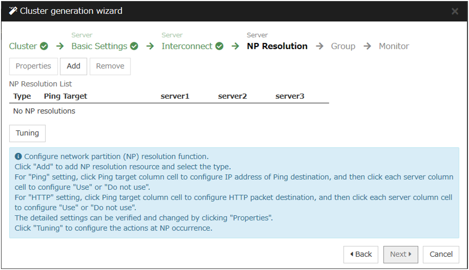
- To use NP resolution in the PING mode, click Add and add a row to NP Resolution List, click Type and select Ping, click the cell of Ping Target, and then enter the IP addresses of the ping destination target devices (such as a gateway). When multiple IP addresses separated by commas are entered, they are regarded as isolated from the network if there is no ping response from any of them.If the PING mode is used only on some servers, set the cell of the server not to be used to Do Not Use.If some ping-related parameters must be changed from their default values, select Properties, and then specify the settings in the Ping NP Properties dialog box.For the setup example in this chapter, a row for the PING mode is added and 192.168.0.254 is specified for Ping Target.

- To use NP resolution in the HTTP mode, add a row to NP Resolution List by clicking Add, click the cell in Type column, and select HTTP/HTTPS. Then click Properties, enter the address of the Web server in Target Host, and enter the port number in Service Port. If the HTTP mode is used only on some servers, set the cells of the servers not to be used to Do Not Use.For the setup example in this chapter, the HTTP mode is not used.
- Specify the operation to perform when a network partition is detected. Select Stop the cluster service or Stop the cluster service and shutdown OS.For the setup example in this chapter, Stop the cluster service is selected.
Click Next.
6.10.2. Creating a failover group
Add a failover group that executes an application to the cluster. (Below, failover group is sometimes abbreviated to group.)
6.10.2.1. Add a failover group
Set up a group that works as a unit of failover at the time an error occurs.
In the Group List, click Add.
In the Group Definition dialog box, enter the group name (failover1) in the Name box, and click Next.
Add svg1 and svg2 from the Available Server Groups list to the Server Groups that can run the Group in the order in the order of svg1, svg2.
- Specify each attribute value of the failover group. Because all the default values are used for the setup example in this chapter, click Next.The Group Resource is displayed.

6.10.2.2. Add a group resource (Floating IP address)
Add a group resource, a configuration element of the group, to the failover group you have created in "6.10.2.1. Add a failover group".
Click Add in the Group Resource List.
The Resource Definition of Group | failover1 dialog box is displayed. In this dialog box, select the group resource type Floating IP resource in the Type box, and enter the group name fip1 in the Name box. Click Next.
The Dependent Resources page is displayed. Specify nothing. Click Next.
The Recovery Operation at Activation Failure Detection and Recovery Operation at Deactivation Failure Detection pages are displayed. Click Next.
Enter the IP Address 10.0.0.12 in the IP Address box. Click Finish.
6.10.2.3. Add a group resource (Hybrid disk resource)
In the Group Resource List, click Add.
In the Resource Definition of Group | failover1 dialog box, select the group resource type Hybrid disk resource in the Type box, and enter the group resource name hd1 in the Name box. Click Next.
The Dependent Resources page is displayed. Specify nothing. Click Next.
The Recovery Operation at Activation Failure Detection and Recovery Operation at Deactivation Failure Detection pages are displayed. Click Next.
Select the mirror partition device name /dev/NMP1 in Mirror Partition Device Name box. Enter the mount point /mnt/sdb2, the data partition device name /dev/sdb2 and the cluster partition device name /dev/sdb1 in the respective box. In the File System dialog box, select the file system ext3. Click Finish.
6.10.2.4. Add a group resource (EXEC resource)
Add an exec resource that can start and stop the application from a script.
In the Group Resource List, click Add.
In the Resource Definition of Group | failover1 dialog box, select the group resource EXEC resource in the Type box, and enter the group resource name exec1 in the Name box. Click Next.
The Dependent Resources page is displayed. Specify nothing. Click Next.
The Recovery Operation at Activation Failure Detection and Recovery Operation at Deactivation Failure Detection pages are displayed. Click Next.
- Select Script created with this product. Edit the script if applications to be used in EXPRESSCLUSTER are already decided. Users may edit this script to describe the procedure to start and stop a group of applications. Click Next.The Group Resource List of the failover1 should look similar to the following:

- Click Finish.
6.10.3. Creating monitor resources
Add a monitor resource that monitors a specified target to the cluster.
6.10.3.1. Add a monitor resource (Disk monitor resource)
Add monitor resources to monitor the target disk. "diskw" is used as an example of a monitor resource to be added.
In the Group list, click Next.
In the Monitor Resource List, click Add.
The Monitor Resource Definition dialog box is displayed. The first monitor resource information is created by default when the cluster name is defined. The sixth and the seventh monitor resources are created in default when the hybrid disk resource is added. Select the monitor resource type Disk monitor in the Type box, and enter the monitor resource name diskw1 in the Name box. Click Next.
Configure the monitor settings. Do not change the default value and click Next.
Select Method (READ(RAW)) and enter Monitor Target (/dev/sdb2). Click Next.
Set the recovery target. Click Browse.
Click LocalServer in the tree view, click OK. LocalServer is set to the Recovery Target.
Select Stop the cluster service and shut down OS in the Final Action box, and click Finish.
6.10.3.2. Add a monitor resource (IP monitor resource)
In the Monitor Resource List, click Add.
In the Monitor Resource Definition dialog box, select the monitor resource type IP monitor in the Type box, and enter the monitor resource name ipw1 in the Name box. Click Next.
Enter the monitor settings. Change nothing from the default values. Click Next.
- Click Add.Enter the IP address to be monitored (10.0.0.254) in the IP Address box, and then click OK.
Note
For the monitoring target of the IP monitor resource, specify the IP address of a device (such as a gateway) that is assumed to always be active on the public LAN.
The entered IP address is specified in the IP Addresses list. Click Next.
Specify the recovery target. Click Browse.
Select All Groups in the tree view and click OK. All Groups is set to Recovery Target.
- Click Finish.The Monitor Resource List should look similar to the following:

6.10.4. Disabling the cluster operation
When you click Finish after creating a monitor resource, the following popup message appears:

Clicking No disables automatic group startup, recovery on the activation/deactivation failure of a group resource, and recovery on the failure of a monitor resource. To start a cluster for the first time after creating the cluster configuration data, it is recommended to disable the automatic start and the recovery and to check the cluster configuration data for errors.
To disable the cluster operation, go to Cluster properties -> Extension tab tab -> Disable cluster operation.
Note
Even if the cluster operation is disabled, failover is performed upon a server failure.
Disabling the recovery on the failure of a monitor resource is not applied to user mode monitor resources.
6.10.5. Modify cluster properties
In the config mode of Cluster WebUI, click Properties of Cluster.
The Cluster Properties dialog box is displayed. Click Interconnect tab. Clear the Server Down Notification check box.
Click OK.
This completes creating the cluster configuration information. Proceed to "6.12. Creating a cluster".
6.11. Saving the cluster configuration data
The cluster configuration data can be saved to any directory., you can apply the saved cluster information via the Cluster WebUI to the server machine with the EXPRESSCLUSTER Server installed.
To save the configuration information, follow the procedure below:
Click Export in the config mode of Cluster WebUI.
Select a location to save the data and save it. Specify this directory when executing the creation command later.
Note
One file (clp.conf) and one directory (scripts) are saved. If any of these are missing, the command to create a cluster does not run successfully. Make sure to treat these two as a set. When new configuration data is edited, clp.conf.bak is created in addition to these two.
6.12. Creating a cluster
After creating and/or modifying a cluster configuration data, apply the configuration data on the servers that constitute a cluster and create a cluster system.
6.12.1. How to create a cluster
After creation and modification of the cluster configuration data are completed, create a cluster in the following procedures.
- Click Apply the Configuration File on the File in the config mode of Cluster WebUI.If the upload succeeds, the message saying "The application finished successfully."
Select the Operation Mode on the drop down menu of the toolbar in Cluster WebUI to switch to the operation mode.
Execute a relevant procedure below depending on the resource to use.
When using a hybrid disk resource
For details about how to initialize the hybrid disk resources, see "2.8.3. Partition settings for Hybrid disk resource (Required for the Replicator DR)" in "2.8. Settings after configuring hardware" in this guide.
After executing above in the relevant server in the cluster, proceed the following steps.
Restart all servers. After restarting the servers, clustering starts and the status of clustering is displayed on Cluster WebUI.
When using mirror disk resource
Restart all servers. After restarting the servers, clustering starts and the status of clustering is displayed on Cluster WebUI.
When using neither mirror disk resource nor hybrid disk resource
Select Start Cluster in the Status tab of Cluster WebUI and click. Clustering starts and the status of clustering is displayed on Cluster WebUI.
For how to operate and check the Cluster WebUI, see the online manual from the
button on the upper right of the screen.

7. Verifying a cluster system
This chapter describes how you change the cluster configuration.
This chapter covers:
7.1. Verifying operations using the Cluster WebUI
This chapter provides instructions for verifying the cluster system using the Cluster WebUI. The Cluster WebUI is installed at the time of the EXPRESSCLUSTER Server installation. Therefore, it is not necessary to install it separately. The Cluster WebUI can be accessed from a management PC. The following describes how to access to the Cluster WebUI.
See also
For system requirements of the Cluster WebUI, refer to "Installation requirements for EXPRESSCLUSTER" in the "Getting Started Guide".
Follow the steps below to verify the operation of the cluster after creating the cluster and connecting to the Cluster WebUI.
See also
For details on how to use the Cluster WebUI, see. If any error is detected while verifying the operation, troubleshoot the error by referring to "Troubleshooting" in the "Reference Guide".
- Check heartbeat resourcesVerify that the status of each server is online on the Cluster WebUI.Verify that the heartbeat resource status of each server is normal.
- Check monitor resourcesVerify that the status of each monitor resource is normal on the Cluster WebUI.
- Start up a groupStart a group.Verify that the status of the group is online on the Cluster WebUI.
- Check a disk resourceVerify that you can access the disk mount point on the server where the group having a disk resource is active.
- Check a mirror disk resource/hybrid disk resourceVerify that you can access the disk mount point on the server where the group having a mirror disk resource/hybrid disk resource is active.
- Check a floating IP resourceVerify that you can ping a floating IP address while the group having the floating IP resource is active.
- Check an exec resourceVerify that an application is working on the server where the group having an exec resource is active.
- Stop a groupStop a group.Verify that the status of the group is offline on the Cluster WebUI.
- Move a groupMove a group to another server.Verify that the status of the group is online on the Cluster WebUI.Move the group to all servers in the failover policy and verify that the status changes to online on each server.
- Perform failoverShut down the server where a group is active.After the heartbeat timeout, check to see the group has failed over. Verify that the status of the group becomes online on the failover destination server on the Cluster WebUI.
- Perform failbackWhen the automatic failback is set, start the server that you shut down in the previous step, "9. Failover." Verify that the group fail back to the original server after it is started using the clpstat command. Verify that the status of group becomes online on the failback destination server on the Cluster WebUI.
- Shut down the clusterShut down the cluster. Verify that all servers in the cluster are successfully shut down using the clpstat command.
7.2. Verifying operation by using commands
Follow the steps below to verify the operation of the cluster from a server constituting the cluster using command lines after the cluster is created.
See also
For details on how to use commands, see "EXPRESSCLUSTER command reference" in the "Reference Guide". If any error is detected while verifying the operation, troubleshoot the error referring to "Troubleshooting" in the "Reference Guide".
- Check heartbeat resourcesVerify that the status of each server is online by using the clpstat command.Verify that the heartbeat resource status of each server is normal.
- Check monitor resourcesVerify that the status of each monitor resource is normal by using the clpstat command.
- Start groupsStart the groups with the clpgrp command.Verify that the status of groups is online by using the clpstat command.
- Stop a groupStop a group with the clpgrp command.Verify that the status of the group is offline by using the clpstat command.
- Check a Disk resourceVerify that you can access a disk mount point on the server where the group having disk resources is active.
- Check a Mirror disk resource/hybrid disk resourceVerify that you can access the disk mount point on the server where the group having a mirror disk resource/hybrid disk resource is active.
- Check a Floating IP resourceVerify that you can ping a floating IP address while the group having a floating IP resource is active.
- Check an EXEC resourceVerify that an application is working on the server where the group having an exec resource is active.
- Move a groupMove a group to another server by using the clpstat command.Verify that the status of the group is online by using the clpstat command.Move the group to all servers in the failover policy and verify that the status changes to online on each server.
- Perform failoverShut down a server where a group is active.After the heartbeat timeout, check to see the group has failed over by using the clpstat command. Verify that the status of the group becomes online on the failover destination server using the clpstat command.
- Perform failbackWhen the automatic failback is set, start the server which you shut down in the previous step, "9. Failover." Verify that the group fails back to the original server after it is started using the clpstat command. Verify that the status of the group becomes online on the failback destination server using the clpstat command.
- Shut down the clusterShut down the cluster by using the clpstdn command. Verify that all servers in the cluster are successfully shut down.
8. Modifying the cluster configuration data
This chapter describes how you modify the cluster configuration data.
This chapter covers:
8.1. Modifying the cluster configuration data
The following describes procedures and precautions of modifying the cluster configuration data after creating a cluster.
8.1.1. Modifying the cluster configuration data by using the Cluster WebUI
Start the Cluster WebUI.
Select the Config Mode from the drop down menu of the tool bar in Cluster WebUI.
Modify the configuration data after the current cluster configuration data is displayed
Upload the modified configuration data. Depending on the modified data, it may become necessary to suspend or stop the cluster and/or to restart by shutting down the cluster. In such a case, uploading is canceled once and the required operation is displayed. Follow the displayed message and do as instructed to perform upload again.
8.2. Applying the cluster configuration data
Apply the cluster configuration data on the EXPRESSCLUSTER Server environment. The way to apply them varies depending on the nature of the changes. For details on how to change parameters and how to apply them, refer to "Parameter details" in the "Reference Guide".
The way you apply changed parameters may affect behavior of the EXPRESSCLUSTER X. For details, see the table below:
The way to apply changes |
Effect |
|---|---|
Upload Only |
The operation of the applications and EXPRESSCLUSTER Server is not affected. Heartbeat resources, group resources or resource monitor does not stop. |
Uploading data and restarting the API service |
The operation of the applications and EXPRESSCLUSTER Server is not affected. Heartbeat resources, group resources or resource monitor does not stop. |
Uploading data and restarting the WebManager server |
The operation of the applications and EXPRESSCLUSTER Server is not affected. Heartbeat resources, group resources or resource monitor does not stop. |
Uploading data and restarting the Information Base service |
The operation of the applications and EXPRESSCLUSTER Server is not affected. Heartbeat resources, group resources or resource monitor does not stop. |
Uploading data after suspending the monitor |
The monitor resource stops. The application continues to run because the group resource does not stop. |
Uploading data after suspending the cluster |
The operation of the EXPRESSCLUSTER Server partly stops. While the EXPRESSCLUSTER daemon is suspended, heartbeat resources and monitor resources stop. Applications continue operations because group resources do not stop. |
Uploading data after stopping the monitor |
The group resource stops. The application stops until the resource is started. |
Uploading data after suspending the group |
The group stops. The application stops until the group is started. |
Uploading data after stopping the cluster |
All the operations of the EXPRESSCLUSTER Server stop.
Because groups are also stopped, applications are stopped until a cluster and groups are started after uploading data.
|
Uploading data after stopping the cluster and mirror agent |
The operation of the whole EXPRESSCLUSTER stops. The application stops until the data is uploaded, the cluster is started and the group is started. |
Shutdown the cluster and restart after
uploading data
|
The application stops until the cluster is restarted and the group is started. |
Note
9. Verifying operation
This chapter provides information on how to run dummy-failure tests to see the behaviors of you r cluster system and how to adjust parameters.
This chapter covers:
9.1. Operation tests
- Transition of recovery operation due to dummy failureWhen dummy failure is enabled, a test must be conducted to check that recovery of the monitor resources in which an error was detected is performed as set.You can perform this test from Cluster WebUI or with the clpmonctrl command. For details, see the online manual or "EXPRESSCLUSTER command reference" in the "Reference Guide".
- Dummy-failure of the shared disks(When the shared disks are RAID-configured and dummy-failure tests can be run)The test must include error, replacement, and recovery of RAID for a shared disk subsystem.
- Set a dummy-failure to occur on a shared disk.
- Recover RAID from the degenerated state to normal state.
For some shared disks, I/O may temporarily stop or delay when they switch to the degenerated operation or when RAID is reconfigured.If any time-out and/or delay occurs in operations such as disk monitoring, adjust the time-out value of each monitor resources. - Dummy-failure of the paths to shared disks(When the path to the shared disk is redundant paths and dummy-failure tests can be run.)The test must include an error in the paths and switching of one path to another.
Set a dummy-failure to occur in the primary path.
It takes time for some path-switching software (driver) to switch the failed path to the path normally working. In some cases, the control may not be returned to the operating system (software).If any time-out and/or delay occurs in operations such as disk monitoring, adjust the time-out value of each monitor resources. - Backup/RestorationIf you plan to perform regular backups, run a test backup.Some backup software and archive commands make CPU and/or disk I/O highly loaded.If any server and/or OS stop, heartbeat delays, delay in monitor resources, or time-out occur, adjust the heartbeat time-out value and/or time-out value of each monitor resources.
Different types of dummy-failure tests for each device and what happen after the tests are described below:
Device/Resource |
Dummy-failure |
What happens |
|---|---|---|
Shared disk device SCSI/FC path |
Unplug the cable on the server side (for a redundant server, unplug both cables) |
When a disk is monitored, failover to the standby server occurs. When no disk is monitored, the operation stops. |
Disk heartbeat resource becomes offline.
A warning is issued to the alert log.
= Operation continues.
|
||
Disk monitor resources detect an error |
||
For FC, power off the FC Switch |
When a disk is monitored, failover to the standby server occurs. When no disk is monitored, the operation stops. |
|
Disk heartbeat resources become offline. |
||
Disk monitor resources detect an error |
||
Interconnect LAN |
Unplug the LAN cable |
Communication between servers continues using a public LAN
Operation continues
|
The LAN heartbeat resource on the interconnect becomes offline.
A warning is issued to the alert log.
= Operation continues.
|
||
An error is detected in an IP monitor resource
Failover to the standby server occurs.
|
||
An error is detected in a NIC Link Up/Down monitor resource
Failover to the standby server occurs.
|
||
Public LAN |
Unplug the LAN cable or power off the HUB |
Communication stops, application stalls or an error occurs.
=These do not result in failover.
|
LAN heartbeat resource on the public LAN becomes inactive.
A warning is issued to the alert log.
= Operation continues.
|
||
An error is detected in an IP monitor resource
Failover to the standby server occurs.
|
||
An error is detected in a NIC Link Up/Down monitor resource.
Failover to the standby server occurs
|
||
UPS |
Unplug the UPS from outlet |
The active server shuts down
Failover to the standby server occurs
|
Array UPS |
Unplug the UPS from outlet |
Both servers shut down
Operation stops
|
LAN for UPS |
Unplug the LAN cable |
UPS becomes uncontrollable.
Operation continues
|
COM |
Unplug the RS-232C cable of the COM heartbeat |
COM heartbeat resource becomes offline.
A warning is issued to the alert log.
Operation continues.
|
OS error |
Run the shutdown command on the active server |
The active server shuts down
Failover to a standby server occurs.
|
Mirror disk connect |
Unplug the LAN cable |
A warning is issued to the alert log (mirroring stops)
Operation continues, but a switch to a standby server becomes impossible.
|
An error is detected in mirror disk monitor resource
Operation continues
|
||
Disk resource |
When Disk Type is not raw
Start up the group after mounting the disk
(Example) # mount /dev/sda2 /mnt/sda2
|
A disk resource does not get activated. |
When Disk Type is raw
Specify the already-used device (the one that is used for the cluster partition) to make it redundant.
|
The disk resource is not activated. |
|
Exec resource |
Write an invalid command in exec resource script
Change "EXIT 0" in the end of script to "EXIT 1"
|
An exec resource does not get activated.
Failover to a standby server occurs.
|
Floating IP address |
Specify the already-used address (the one that is used for server) to make it overlapped |
A floating IP resource does not get activated. |
Virtual IP resource |
Specify the already-used address (the one that is used for server) to make it overlapped |
A virtual IP resource does not get activated. |
Mirror disk resource
Hybrid disk resource
|
Start up the group after mounting the disk
(Example) # mount /dev/sda2 /mnt/sda2
|
A mirror disk resource/hybrid disk resource does not get activated. |
NAS resource |
Start up the group after mounting the disk
(Example) # mount -t nfs <server-name>:/<share-name> /mnt/nas1
|
A NAS resource does not get activated. |
PID monitor resource |
Terminate resident process of monitored exec resource
(Example) # kill <process-ID>
|
Failover to a standby server occurs. |
Volume manager monitor resource |
When Volume Manager is lvm
Manually export the volume group from the standby server.
|
An error is detected in the monitor resource. |
When Volume Manager is vxvm
Stop the VxVM daemon.
|
An error is detected in the monitor resource. |
|
VM resource |
Disconnect the shared disk containing the virtual machine image. |
The VM resource is not activated. |
Start the virtual machine while the VM resource is stopped. |
The VM resource is activated. |
|
VM monitor resource |
Shut down the virtual machine. |
The virtual machine is started by restarting the resource. |
Dynamic DNS resource |
Start the Dynamic DNS resource while the name resolution service on the DNS server is not running. |
Dynamic DNS resource is not activated. |
Dynamic DNS monitor resource |
Shut down a normally operating DNS server or stop the running name resolution service. |
Dynamic DNS monitor resource detects an error and takes action for it. The VHOST resource fails to stop when there is resource reactivation or a failover. |
use the nsupdate command to delete the virtual host name that is registered in the Dynamic DNS resource from the DNS server. |
Dynamic DNS monitor resource registers the virtual host name on the DNS serve again within the monitor interval. |
See also
For information on how to change each parameter, refer to the "Reference Guide".
9.2. Backup procedures
9.2.1. Backing up while EXPRESSCLUSTER is active
To back up the file system while the EXPRESSCLUSTER daemon is active, follow the procedures below.
Make sure the cluster is working normally.
- To prevent the heartbeat time-out caused by highly loaded user space from occurring, change the time-out ratio of EXPRESSCLUSTER by using the time-out temporary adjustment command.If you want to triple the current time-out and make this temporary setting valid for one hour, run the following command:
# clptoratio -r 3 -t 1h - Back up the shared disk, mirrored disk or hybrid disk.For backing up a shared disk, the disk resource in group resources needs to be activated on the server for backup.For backing up a mirror disk or hybrid disk, the mirror disk resource or hybrid disk resource in group resources needs to be activated on the server for backup. However, a backup command for directly accessing partition devices is not supported for mirror disks and hybrid disk.
- Set the time-out ratio adjusted with the time-out temporary adjustment command back to the original:
# clptoratio -i
For details on the command that temporarily adjusts the time-out, see "EXPRESSCLUSTER command reference" in the "Reference Guide".
9.2.2. Backing up while EXPRESSCLUSTER is inactive
To back up the file system while the EXPRESSCLUSTER daemon is inactive, follow the procedures below.
Make sure the cluster is working normally.
Stop the EXPRESSCLUSTER daemon.
# clpcl -t -a- Back up the file system and shared disk.For the shared disk, manually mount the file system on the shared disk you want to back up. Make sure to unmount the file system after you have completed the backup.
Start the EXPRESSCLUSTER daemon.
# clpcl -s -a
9.2.3. Backing up while EXPRESSCLUSTER is inactive (For Replicator or Replicator DR)
9.3. Restoration procedures
You also need to simulate restoration operation before starting to use your cluster system. To restore the file system, follow the procedures below.
9.3.1. Restoring the file system containing the /opt/nec/clusterpro directory
- From a server normally running in the cluster, back up the cluster configuration data to an external medium.
# clpcfctrl --pull -l -x <the path to the directory where the configuration data is stored>
After backing up the data, unmount the external medium.Note
Perform the subsequent procedure on the server to be restored.
- Run the following commnad to disable services on the server to be restored.
clpsvcctrl.sh --disable -a
Execute cluster shutdown by using Cluster WebUI or the clpstdn command, and then, restart the server.
Restore the file system on the server to be recovered (there is no cluster-dependent work).
- Verify if the EXPRESSCLUSTER Server is installed on the restored file system with the following command:
rpm -qi expresscls
For Ubuntu, run the following command.dpkg -s clusterpro
When the EXPRESSCLUSTER Server is installed, proceed to Step (6).When the EXPRESSCLUSTER Server is not installed, proceed to Step (7). - If the EXPRESSCLUSTER Server is installed, run the following command to uninstall it:
rpm -e expresscls
For Ubuntu, run the following command.dpkg -r clusterpro
Note
Do not specify options other than the one stated above.
For troubleshooting a problem that occurs when you uninstall the EXPRESSCLUSTER Server, see "11.1.1. Uninstalling the EXPRESSCLUSTER Server" in "11.1. Uninstallation". - Install the EXPRESSCLUSTER Server.For details, see "4.2. Setting up the EXPRESSCLUSTER Server" in "4. Installing EXPRESSCLUSTER" in this guide. If there is any server in the cluster on which an update of the EXPRESSCLUSTER Server is applied, apply the same update to this server. Make sure that the same version of the EXPRESSCLUSTER Server is installed on all servers in the cluster.
- Mount an external medium in the server where the EXPRESSCLUSTER Server was reinstalled.
Note
You have to restart the server where the EXPRESSCLUSTER Server was reinstalled after reinstallation.
- Register the cluster configuration data which was backed up in Step 1 with the server by running the cluster creation command:
# clpcfctrl --push -l -x <path to the directory where configuration data is saved>Command succeeded.(code:0)
if the command is successfully displayed and completed.
See also
For details on the cluster creation command, see "EXPRESSCLUSTER command reference" in the "Reference Guide".
Unmount the external media and then restart the server.
9.3.3. Restoring the data on the mirror disk or the hybrid disk
The following describes how to restore the data on the mirrored disk resource or the hybrid disk resource.
Restoring while EXPRESSCLUSTER is active
Make sure that the cluster is working normally.
- To prevent the heartbeat time-out caused by heavily loaded user space from occurring, change the time-out ratio of EXPRESSCLUSTER with the time-out temporary adjustment command.If you want to triple the current time-out and make this temporary setting valid for one hour, run the following command.
# clptoratio -r 3 -t 1h - Restore the mirrored disk or the hybrid disk.Mirror disk resource or hybrid disk resource of the group resource should be active on the server where you want to restore them.
Set the time-out ratio adjusted with the time-out temporary adjustment command back to the original.
# clptoratio -iSee also
For details on the command for adjusting time-out temporarily, see "EXPRESSCLUSTER command reference" in the "Reference Guide".
Restoring while EXPRESSCLUSTER is inactive
It is not recommended to restore mirror disk while EXPRESSCLUSTER is inactive.
10. Preparing to operate a cluster system
10.1. Operating the cluster system
10.1.1. Activating a cluster
To activate a cluster, follow the instructions below:
When you are using any shared or external mirror disk, start the disk.
Start all the servers in the cluster.
Note
When you start all the servers in the cluster, make sure they are started within the duration of time set to Server Sync Wait Time on the Timeout tab of the Cluster Properties in the Cluster WebUI. Note that failover occurs if startup of any server fails to be confirmed within the specified time duration.
Note
The shared disk spends a few minutes for initialization after its startup. If a server starts up during the initialization, the shared disk cannot be recognized. Make sure to set servers to start up after the shared disk initialization is completed.
10.1.2. Shutting down a cluster and server
To shut down a cluster or server, use EXPRESSCLUSTER commands or shut down through the Cluster WebUI.
Note
When you are using the Replicator, mirror break may occur if you do not use any EXPRESSCLUSTER commands or Cluster WebUI to shut down a cluster.
10.1.3. Shutting down the entire cluster
The entire cluster can be shut down by running the clpstdn command or executing cluster shutdown from the Cluster WebUI. By shutting down a cluster, all servers in the cluster can be stopped properly as a cluster system.
10.1.4. Shutting down a server
10.1.5. Suspending/resuming a cluster
All heartbeat resources stop.
All monitor resources stop.
Groups or group resources are disabled (cannot be started, stopped, or moved).
The cluster status cannot be displayed or operated by Cluster WebUI or the clpstat command.
The following commands cannot be used:
clpstat
clpcl command options other than --resume
clpdown
clpstdn
clpgrp
clptoratio
clpmonctrl (except for the -c and -v options)
clprsc
- clpcpufreq
10.1.6. How to suspend a cluster
You can suspend a cluster by executing the clpcl command or by using Cluster WebUI.
10.1.7. How to resume a cluster
You can resume a cluster by executing the clpcl command or by using Cluster WebUI.
10.2. Suspending EXPRESSCLUSTER
There are two ways to stop running EXPRESSCLUSTER. One is to stop the EXPRESSCLUSTER daemon, and the other is to disable the EXPRESSCLUSTER daemon.
10.2.1. Stopping the EXPRESSCLUSTER daemon
To stop only the EXPRESSCLUSTER daemon without shutting down the operating system, use the clpcl command.
See also
For more information on the clpcl command, see "EXPRESSCLUSTER command reference" in the "Reference Guide".
10.2.2. Disabling the EXPRESSCLUSTER daemon
- Run the following commnad to disable services on the server where you want to disable the EXPRESSCLUSTER daemon.
clpsvcctrl.sh --disable core mgr
Restart the server by using the Cluster WebUI or the clpstdn command.
10.2.3. Enabling the disabled EXPRESSCLUSTER daemon
Follow the procedures below to enable the disabled EXPRESSCLUSTER daemon again:
- On the server where the EXPRESSCLUSTER daemon is disabled, run the following commnad in the following order to enable services.
clpsvcctrl.sh --enable core mgr
Restart the server.
11. Uninstalling and reinstalling EXPRESSCLUSTER
11.1. Uninstallation
11.1.1. Uninstalling the EXPRESSCLUSTER Server
Note
You must log on as root user when uninstalling the EXPRESSCLUSTER Server. It is recommended that you obtain a cluster configuration before uninstalling the EXPRESSCLUSTER Server. For details, refer to "EXPRESSCLUSTER command reference" in the "Reference Guide".
Follow the procedures below to uninstall the EXPRESSCLUSTER Server:
If the SNMP linkage function has been used, you must cancel the linkage before uninstalling EXPRESSCLUSTER Server. For how to cancel the settings of the SNMP linkage function, see "11.1.2. Canceling the SNMP linkage function settings".
- Run the following commnad to disable the following services.
clpsvcctrl.sh --disable -a
Restart the server by using the Cluster WebUI or the clpdown command.
- Run the rpm -e expresscls command.For Ubuntu, run dpkg -r expresscls.
Note
Do not specify other options than the one stated above.
11.1.2. Canceling the SNMP linkage function settings
Note
To cancel the SNMP linkage function settings, you must log in as the root user.
The description related to Net-SNMP in the uninstallation procedure may vary depending on the distribution.
- Stop the snmpd daemon.
Note
The daemon can usually be stopped by the following command:For an init.d environment:
/etc/init.d/snmpd stop
For a systemd environment:
sytemctl stop snmpd
- Cancel registration of the SNMP linkage function in the configuration file for the snmpd daemon.Open the configuration file with a text editor.Delete the following lines from the configuration file:
dlmod clusterManagementMIB /opt/nec/clusterpro/lib/libclpmgtmib.so
dlmod clusterManagementMIB /opt/nec/clusterpro/lib/libclpmgtmib2.so
Note
The configuration file for the snmpd daemon is usually located in the following directory:/etc/snmp/snmpd.confNote
Delete the OID of EXPRESSCLUSTER from the MIB view (view definition by snmpd.conf) permitted by the snmpd daemon.The OID of EXPRESSCLUSTER is ".1.3.6.1.4.1.119.2.3.207". If you created symbolic links at "4.2.3. Setting up the SNMP linkage function", delete them.
Start the snmpd daemon.
Note
For an init.d environment:
/etc/init.d/snmpd start
For a systemd environment:
systemctl start snmpd
11.2. Reinstallation
11.2.1. Reinstalling the EXPRESSCLUSTER Server
To reinstall EXPRESSCLUSTER Server on the entire cluster
To reinstall the EXPRESSCLUSTER Server, follow the procedures below:
- Uninstall the EXPRESSCLUSTER Server.
- Install the EXPRESSCLUSTER Server and recreate the cluster.For details, see "4.2. Setting up the EXPRESSCLUSTER Server"
To reinstall EXPRESSCLUSTER Server on some servers in the cluster
To reinstall the EXPRESSCLUSTER X, follow the procedures below:
- Uninstall the EXPRESSCLUSTER Server.
- Install the EXPRESSCLUSTER Server RPM.For details, refer to "4.2.1. Installing the EXPRESSCLUSTER RPM".
Note
You have to restart the server on which you reinstalled the EXPRESSCLUSTER Server.
- Distribute the configuration data to servers of which the EXPRESSCLUSTER Server has been reinstalled from the server where it has not been reinstalled. Log on to one of the server where the EXPRESSCLUSTER Server has not been reinstalled. Run one of the following commands:
clpcfctrl --push -h <Host_name_of_a_server_where_the_EXPRESSCLUSTER_Server_was_reinstalled>
clpcfctrl --push -h <IP_address_of_a_server_where_the_EXPRESSCLUSTER_Server_was_reinstalled>
The following message is displayed if the data has successfully been distributed.Command succeeded.(code:0)
If the fixed-term license is used, run the following command.clplcnsc --reregister <a folder path for saved license files>
Note
For troubleshooting problems that occur while you are running the clpcfctrl command, see "EXPRESSCLUSTER command reference" in the "Reference Guide".
If mirror resources are configured on the distributed configuration data, initializing the device specified as a cluster partition of mirror resources is required. Run the clpmdinit command to initialize it. For details, see "EXPRESSCLUSTER command reference" in the "Reference Guide".
Register the license only if the option of the node license will be used on the server where the EXPRESSCLUSTER Server is reinstalled. For more information, refer to "5.3. Registering the node license ".
Restart the server on which you reinstalled the EXPRESSCLUSTER Server.
12. Troubleshooting
12.1. Error messages when installing the EXPRESSCLUSTER Server
Behavior and Message |
Cause |
Action |
|---|---|---|
failed to open //var/lib/rpm/packages.rpm
error: cannot open //var/lib/rpm/packages.rpm
|
The user logged on is not root user. |
Log on as root user. |
error: package expresscls-* is already installed
|
The EXPRESSCLUSTER is already installed. |
Uninstall the EXPRESSCLUSTER and reinstall it. |
warning: EXPRESSCLUSTER : The mirror driver is not supported this distribution. |
The mirror driver does not support the distribution of a server where EXPRESSCLUSTER is installed. |
The mirror disk resource does not run on the distribution the mirror driver does not support. |
warning: EXPRESSCLUSTER : The khb driver is not supported this distribution. |
The clpkhb driver does not support the distribution of a server where EXPRESSCLUSTER is installed. |
The kernel mode LAN heartbeat does not run on the distribution the clpkhb does not support. |
warning: EXPRESSCLUSTER : The ka driver is not supported this distribution. |
The clpka driver does not support the distribution of a server where EXPRESSCLUSTER is installed. |
The module which uses the clpka driver does not run on the distribution the clpka does not support. |
12.2. Error messages when uninstalling the EXPRESSCLUSTER Server
Behavior and Message |
Cause |
Action |
|---|---|---|
failed to open //var/lib/rpm/packages.rpm
error: cannot open //var/lib/rpm/packages.rpm
|
The user logged on is not root user. |
Log on as root user. |
error: EXPRESSCLUSTER is running |
The EXPRESSCLUSTER is active. |
Disable Auto Startup of services, restart the server, and uninstall the EXPRESSCLUSTER again. |
12.3. Licensing
Behavior and Message |
Cause |
Action |
|---|---|---|
When the command was executed, the following message appeared in the console:
Log in as root.
|
The command was executed by a general user. |
Log on as root user or log on again after changing to root user with su -. |
When the command was executed at the license registration, the following message appeared in the console:
Command succeeded. But the license was not applied to all the servers in the cluster because there are one or more servers that are not started up.
|
The transaction server may not be active, or the cluster configuration data may be yet to be distributed. |
Check again whether the transaction server is activated and the cluster configuration data is distributed on all servers. If either of them is not done yet, complete the task and register the license again. |
When the cluster was shut down and rebooted after distribution of the configuration data created by the Cluster WebUI to all servers, the following message was displayed on the alert log, and the cluster stopped.
The license is not registered. (Product name:%1)
%1: Product name
|
The cluster has been shut down and rebooted without its license being registered. |
Register the license according to "5. Registering the license". |
When the cluster was shut down and rebooted after distribution of the configuration data created by the Cluster WebUI to all servers, the following message appeared on the alert log, but the cluster is working properly.
The number of licenses is insufficient. The number of insufficient licenses is %1. (Product name:%2)
%1: The number of licenses in short of supply
%2: Product name
|
The number of licenses is insufficient. |
Obtain a license and register it. |
While the cluster was operated on the trial license, the following message appeared and the cluster stopped.
The trial license has expired in %1. (Product name:%2)
%1: Trial end date
%2: Product name
|
The license has already expired. |
Ask your sales agent for extension of the trial version license, or obtain and register the product version license. |
While the cluster was operated on the fixed term license, the following message appeared.
The fixed term license has expired in %1. (Product name:%2)
%1: Fixed term end date
%2: Product name
|
The license has already expired. |
Obtain the license for the product version from the vendor, and then register the license. |
13. Glossary
- Cluster partition
- A partition on a mirror disk. Used for managing mirror disks.(Related term: Disk heartbeat partition)
- Interconnect
- A dedicated communication path for server-to-server communication in a cluster.(Related terms: Private LAN, Public LAN)
- Virtual IP address
IP address used to configure a remote cluster.
- Management client
Any machine that uses the Cluster WebUI to access and manage a cluster system.
- Startup attribute
A failover group attribute that determines whether a failover group should be started up automatically or manually when a cluster is started.
A disk that multiple servers can access.
A cluster system that uses one or more shared disks.
- Switchable partition
- A disk partition connected to multiple computers and is switchable among computers.(Related terms: Disk heartbeat partition)
- Cluster system
Multiple computers are connected via a LAN (or other network) and behave as if it were a single system.
- Cluster shutdown
To shut down an entire cluster system (all servers that configure a cluster system).
- Active server
- A server that is running for an application set.(Related term: Standby server)
- Secondary server
- A destination server where a failover group fails over to during normal operations.(Related term: Primary server)
- Standby server
A server that is not an active server. (Related term: Active server)
- Disk heartbeat partition
A partition used for heartbeat communication in a shared disk type cluster.
- Data partition
- A local disk that can be used as a shared disk for switchable partition. Data partition for mirror disks or hybrid disks.(Related term: Cluster partition)
- Network partition
- All heartbeat is lost and the network between servers is partitioned.(Related terms: Interconnect, Heartbeat)
- Node
A server that is part of a cluster in a cluster system. In networking terminology, it refers to devices, including computers and routers, that can transmit, receive, or process signals.
- Heartbeat
- Signals that servers in a cluster send to each other to detect a failure in a cluster.(Related terms: Interconnect, Network partition)
- Public LAN
- A communication channel between clients and servers.(Related terms: Interconnect, Private LAN)
- Failover
The process of a standby server taking over the group of resources that the active server previously was handling due to error detection.
- Failback
A process of returning an application back to an active server after an application fails over to another server.
- Failover group
A group of cluster resources and attributes required to execute an application.
- Moving failover group
Moving an application from an active server to a standby server by a user.
- Failover policy
A priority list of servers that a group can fail over to.
- Private LAN
- LAN in which only servers configured in a clustered system are connected.(Related terms: Interconnect, Public LAN)
- Primary (server)
- A server that is the main server for a failover group.(Related term: Secondary server)
- Floating IP address
- Clients can transparently switch one server from another when a failover occurs.Any unassigned IP address that has the same network address that a cluster server belongs to can be used as a floating address.
- Master server
The server displayed at the top of the Master Server in Server Common Properties of the config mode of Cluster WebUI
- Mirror disk connect
LAN used for data mirroring in mirror disk or hybrid disk. Mirror connect can be used with primary interconnect.
- Mirror disk type cluster
A cluster system that does not use a shared disk. Local disks of the servers are mirrored.